1
Chapter 4: Configuring the CTRIO Inputs
1
2
3
4
5
6
7
8
9
10
11
12
13
14
A
B
C
D
Pulse Catch
4–8
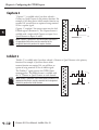
The CTRIO “Pulse Catch” function allows a very short duration pulse to be qualified and
lengthened to a time period long enough to guarantee that it is seen by the CPU. CPU scans
necessarily vary with the length and complexity of the user’s program. A scan frequency of
several milliseconds, or more, is common. A pulse that lasts less than one millisecond, is
typically hard to catch during the CPU scan.
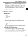
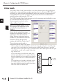
The CTRIO module’s Pulse Catch function sees the fast incoming signal and holds its status
in a status bit until the CPU can see it. A
discrete output(s) can also be tied to
follow the Pulse Catch input.
NOTE: To insure proper operation, the field
device wiring and the configuration must be
compatible. For wiring information see
Chapter 2.
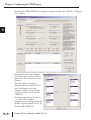
Notice that the module’s four input
terminals are represented by the A, B, C,
and D boxes on the left side of this
dialog. If you are wiring your input to
terminal 1C, you will need to select the
Channel 1 tab near the top of this
window and click Pulse Catch in box C.
Three selections must be made in
conjunction with the Pulse Catch option.
1. First, a decision must be made whether to look for the rising edge of the pulse or the falling edge
of the pulse. This is a critical decision. Careful attention should be paid to the type of output the
field device generates. If the signal voltage is normally low, but a short duration pulse sends the signal
to the ON state, you will want to trigger off the rising
edge, and vice versa.
2. The second decision you will need to make is the
minimum pulse width you want to capture. Transients
below this width will not be recorded. Set this value by
typing the desired value in the “Minimum Width In”
field.
3. The final decision to be made is the length of pulse
the CTRIO module should send in response to the
input pulse. Make this setting by typing in the desired
value in the “Pulse Out Width” field.
1A
2A
1B
2B
1C
2C
1D
2D
1M
2M
NC
C2
C0
Y2
Y0
C3
C1
Y3
Y1
Counter I/O User Manual, 2nd Ed., Rev. D
n + 20.8
status bit
D