1
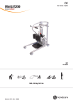
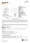
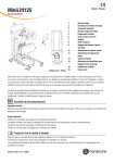
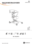
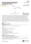
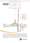
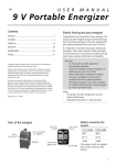
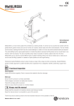
MiniLift125
User Manual - English
SystemRoMedic
TM
400641434
SWL: 125 kg/275 lbs
Manual nr: 884 En Ver. 5 150305
Table of contents
Assembly of MiniLift125.......................................................... 3
- Final inspection ..................................................................................... 4
Using the product....................................................................5-10
- Important information .......................................................................... 5
- Safe working load.................................................................................. 5
- The control box and battery have the following features............................. 6
- Charging batteries.................................................................................. 6
- Hand control.......................................................................................... 7
- Emergency stop..................................................................................... 7
- Emergency lowering............................................................................... 7
- Instructions for use................................................................................ 8
- Using MiniLift125................................................................................... 9
- Trouble-shooting ..................................................................................10
Accessories...................................................................................10
Maintenance................................................................................. 11
Technical information..............................................................12
- Dimensions...........................................................................................13
2
M A N U A L SystemRoMedic
TM
MiniLift125
1
2
3
4
5
SystemRoMedic
TM
REV.
2
3
4
5
6
7
8
10
9
11
A
A
1. Lift arm
2. Hooks for lift vest/sling
3.
Hand control
4.
Leg support
5.Footplate
6.
Rear castor wheels with brakes
7.Battery
8.
Emergency stop
9.
Adjustment of leg support
10.
Manual emergency lowering
11.
Electrical emergency
lowering
12.
Charging lamp
13. Locking mechanism for
adjustment of lift arm
14. Handles
14
B
13
1
10
7
DESCRIP
12
C
2
B
9
3
D
4
E
8
11
12
F
6
C
5
G
15
NAME
DRAWN
15. DATE
hc-jope
2010-07-27
APPROVED BY
STATUS:
Front castors
TITLE
COMMENTS:
Unless otherwise stated, general
tolerances according to ISO 2768-m
SIZE
DWG. NO.
REV.
A2
MiniLift125 is a mobile sit-to-stand lift which has been developed to, as gently as possible, assist the user when rising
MATERIAL:
SCALE:1:4
2
WEIGHT:
g
SHEET 1 OF 1
from a sitting to a standing position. When MiniLift125 is combined with the appropriate lifting accessories, the user getsNAME
3
4
5
6
7
8
9
10
12
11
support under the feet, for the front of the lower legs and behind the back, which provides for a safe and secure
APPROVED BY
DRAWN
sit-to-stand procedure.
DATE
139402makn@z40
2014-09
STATUS:
D
COMMENTS:
Unless
To be able to understand how comfortable MiniLift125 is compared with other sit-to-stand devices on the market,
it otherwise stated,
general tolerances
according
must be tried! The construction safely moves the user forwards and upwards in a natural movement pattern and,
at the to ISO 2768-m
same time, the leg muscles and balance is exercised
1
2
3
This drawing and any information or descriptive ma
and must not be disclosed, loaned, copied or used
Functional inspection
Visual inspection
Inspect lift functions regularly. Check to ensure that material is free from damage.
Before use:
Ensure that the product is correctly assembled.
Check slingbar connection and safety latch function.
Check lift and base-width movement.
Check to ensure that the actuator is correctly installed.
Always read the user manual
Always read the user manuals for all assistive devices used during a transfer.
Keep the user manual where it is accessible to users of the product.
The lift may only be used by persons who have received instruction in the operation of the lift.
SystemRoMedic M A N U A L
TM
3
Assembly of MiniLift125
Check to ensure that all components are included
Lift motor, control box, battery pack, base with motor, footplate, hand control and cord, manual and charging cable.
Screws and screw covers should also be included (see below).
Assembly
Place the upper section on the lower section and lower it carefully into place (picture 1). Press it fully into place and
1
tighten all four screws. Finally, place the plastic covers over the screws (picture 2).
2
3
4
5
6
7
8
9
10
11
12
13
14
15
16
A
A
1
2
3
4
5
6
7
8
9
10
11
12
13
14
15
16
A
A
B
B
B
B
C
C
C
C
D
D
D
D
E
E
E
E
F
F
F
F
G
G
G
G
H
H
H
H
J
J
J
J
K
K
K
K
NAME
L
2
DRAWN
STATUS:
Unless otherwise stated, general
tolerances according to ISO 2768-m
DRAWN
1
DATE
2010-04-26
TITLE
COMMENTS:
NAME
L
hc-mabr
APPROVED BY
M
APPROVED BY
DATE
hc-mabr
SIZE
DWG. NO.
REV.
A1
MATERIAL:
2010-04-26
SCALE:1:1
1
STATUS:
2
3
4
5
6
7
8
9
10
11
WEIGHT:
g
SHEET 1 OF 1
12
TITLE
COMMENTS:
Unless otherwise stated, general
tolerances according to ISO 2768-m
SIZE
DWG. NO.
REV.
A1
MATERIAL:
M
SCALE:1:3
1
2
3
4
5
6
7
8
9
10
11
WEIGHT:
g
SHEET 1 OF 1
12
Mount the footplate on the crossbar and then lower it (picture 3).
3
Mount the leg support by inserting the crossbars on the back into the fixtures
on the lift (4), and then tighten.
4
Connect cables: Hand control cord in HS, cable for lift unit on mast in outlet
M1 and cable for base-width motor in outlet M2 (5).
5
HS
4
M1
M2
M A N U A L SystemRoMedic
TM
F
Final inspection
G
Check to ensure that no parts have been left in the packaging.
Inspect the lift for signs of wear and damage.
H
Check all four castor wheels and castor wheel locks.
Check all connections and fixtures including screws and bolts.
J
B
K
L
DRAWN
STATUS:
COMMENTS:
Unless otherwise
tolerances acc
pressing either the up or down button. If nothing happens when the up or down
M
buttons are pressed, the emergency stop is functioning properly.
1
2
3
4
5
6
7
8
9
10
11
12
C
Grasp the hand control, press the up button and run the lift arm all the way up. Then,
press the down button and run the lift arm all the way down.
Test base-width adjustment function. Press the button for base-width adjustment to
widen the base fully, and then press the other button to narrow the base again.
D
Test lift function by lifting a person (not a user) using an approved sling. At the same
time, check the emergency lowering function with someone on the lift. See section on
Emergency lowering.
1
2
If the lift is functioning correctly, connect the charger and check to ensure that the
charging lamp on the control box lights up.
NOTE!
Before the lift is used for the first time, it must be charged for at least 4 hours. See
section on charging batteries.
Keep the manual where it is accessible to users of the product.
SystemRoMedic M A N U A L
TM
h
APPROVED BY
Check the emergency stop function by activating the emergency stop, and then
5
Using the product
Important Information
• The lift must be assembled according to the instructions provided by Handicare.
• The lift may only be used on a level floor.
• Lifting accessories must be properly fitted and tested in relation to the user’s needs and functional ability.
• Under no circumstances may the safe working load be exceeded. See section on Technical information and the
product label on the lift.
• Never move the lift by pulling on the actuator!
Do not push
• The lift must not be used or immersed in or under water including showering.
• The lift should not be left / stored in a high humidity environment.
• The lift must not be charged in a wet room.
• To ensure optimal function, the lift must be inspected regularly. See section on other maintenance details.
• Warranty applies only if repairs or alterations are made to the product by personnel who are authorized by Handicare.
• Using lifting accessories other than those approved can entail a risk.
Safe working load
Different products on the same lift system (lift unit, lifting sling and other lifting accessories) may have different allowable
safe working loads. The lowest allowable safe working load always determines the safe working load of the assembled
system. Always check the safe working loads for the lift and accessories before use. Contact your dealer if you have any
questions.
6
M A N U A L SystemRoMedic
TM
The control box and battery have the following
features
1. 2. 3. 4.
5. 6. 7. 8. 9. 9
Emergency stop
Charging lamps
Display showing battery charge level
Charger cable
Connection
B for base-width adjustment motor
Connection for lift arm actuator
Connection for hand control
Electrical emergency lowering
Handle for lifting battery
1
8
2
1
C
2
2
3
7
4
6
5
A
Charging batteries
A tone when using the lift indicating that the batteries need recharging.
Charge the lift after use to ensure that the battery is always fully charged.
Lock the castor wheels when charging the battery.
D
B
1. Connect the charging cable to a power outlet.
2. Check to ensure that the lamps on the control box light up. The green LED lamp
indicates that the charger is receiving power and the yellow LED lamp indicates that the
battery is charging.
3. Charging stops automatically when the battery is fully charged.
1
2
3
Wall-mounted charger.
1. Remove the battery pack from the lift and place it in the wall-mounted charger.
2. Check to ensure that the LED lamp on the front of the charger lights up.
NOTE!
C
Before the lift is used for the first time, it must be charged for at least 4 hours.
For maximum battery life, charge batteries regularly. We recommend daily charging when
the lift is used daily.
If the emergency stop is active then the lift can not be charged.
SystemRoMedic M A N U A L
TM
7
Hand control
A
Raising/lowering the lift arm
Symbol indicate direction of travel.
Motion stops as soon as the button is released.
Widening/narrowing the base
Markings on the buttons indicate function.
Motion stops as soon as the buttons are released.
B
1
Emergency stop
2
To activate emergency stop:
Press the red emergency stop button on the control box.
A
Resetting:
Turn the button in the direction of the arrows until the button pops
out.
C
Emergency lowering
Manual emergency
Manual emergency lowering:
lowering
Lift the red regulator upward.
B
Electrical emergency lowering:
For electrical emergency, use the down button on the control box.
Use a narrow object such as a pen.
D
Electrical emergency
lowering
1
2
C
8
D
M A N U A L SystemRoMedic
TM
Instructions for use
These instructions must be followed for correct use of MiniLift125.
Caution:
The actuator does not lower the lift arm when the lift is being lowered. This reduces the risk of the user being pinched
by the lift arm, but as a result, the lift arm may at first catch, and then suddenly fall. To prevent this, the lift arm must be
loaded throughout the entire lowering procedure, so that it is always supported by the actuator.
Hand control functions:
The hand control has four functions: up and down (lift arm), out and in (base width).
Two functions cannot be used at the same time.
NOTE: The hand control functions do not operate if the emergency stop button is activated.
Transferring and lifting the user:
The width of the base must be correctly adjusted to ensure optimal safety.
NOTE: MiniLift125 is not intended for transporting users. It may only be used for short transfers.
Caution: Never move the lift by pulling on the actuator.
Caution: Ensure that the user’s feet do not get caught between the footplate and the floor. Ensure that the user’s feet do
not get caught between the footplate and the base when adjusting the base width.
SystemRoMedic M A N U A L
TM
9
Using MiniLift125
Place an appropriately sized ThoraxSling behind and below the user’s hips,
(see manual for ThoraxSling).
When the user has placed /his/her feet on the footplate, move the lift forward towards the user. Place the lift as close as possible to the user. Take
care to ensure that the user’s shins are resting securely against the leg
support, and then adjust the leg support so that it does not press against
the user’s kneecaps (about 2 cm lower).
Raise the locking handle on the lift arm (2) and pull the lift arm out as far as
possible towards the user.
Select the sling loop that reaches the hook on the lift arm (shortest loop
alternative). Hook the lift loops to the underside of the slingbar.
Raise the locking handle and draw the boom back, so that the lift straps
on the sling are stretched, and then lower the locking handle back into
position.
Instruct the user to allow himself/herself to be supported behind the back
during raising. Raise the lift to the desired height and ensure that the user
is standing with both feet on the footplate and is grasping the sling bar
handles with both hands to avoid being pinched between the sling bar and
lift loops.
Helpful hint:
Use a longer loop alternative for short users and for users that cannot be
fully raised.
Use a longer loop alternative for taller users, and pull the lift arm out to
allow the user to rise to a standing position.
10
M A N U A L SystemRoMedic
TM
Trouble-shooting
If the lift or base-width adjustment cannot be activated, check the following:
- That the emergency stop funktion is activated.
- That all cables are properly and securely connected. Pull out the contact and plug it in again firmly.
- That battery charging is not in progress.
- That the battery is charged.
If the lift is not working properly, contact your dealer.
If the lift makes unusual noises:
- Try to determine the source of the sound. Take the lift out of operation and contact your dealer.
Accessories
ThoraxSling, polyester, XS-XXL, article no.: 45500003-009
ThoraxSling, wipeable, S-XXL, article no.: 45500004-009
ThoraxSling, with seat support, polyester, S-XL, article no.: 45600004-008
ThoraxSling, with seat support, disposable, non-woven, S-XL,
article no.: 45690004-008
CalfStrap, article no.:70200033
SlingBarWrap MiniLift, wipeable, article no.: 70200012
For MiniLift160EE, 60300012, 600300013
Hand control HB33-6, 6 buttons, with service, battery status and overload
indicators, article no.: 70200089
SystemRoMedic M A N U A L
TM
11
Maintenance
The lift must undergo thorough inspection at least once per year. Inspection must be performed by authorized personnel
and in accordance with Handicare’s service manual.
Repairs and maintenance may only be done by authorized personnel using original spare parts.
Spent batteries are to be left at the nearest recycling station. Spent batteries can also be returned to
Handicare or a Handicare dealer for recycling.
Cleaning/disinfection
Clean the lift with warm water or rubbing alcohol and ensure that the castor wheels are free of dirt and hair. Do not use
cleaning agents containing phenol or chlorine, as this may damage the material.
Storage and transportation
If the lift is not to be used for some time or e.g., during transport, we recommend that the emergency stop button be
pressed in. The lift should be transported and stored in -10 ° C to + 50 ° C and in normal humidity, 30% -75 %. The air
pressure should be between 700 and 1060 hPa. Let the lift reach room temperature before the batteries are charged or
the lift is used.
+50
+50 °C
ºC
-10
-10 °C
ºC
70070hPa
kPa
106 kPahPa
1060
75%
75%
30%
30%
Service agreements
Handicare offers the possibility of service agreements for maintenance and regular testing of your mobile lift. Contact
your local Handicare representative.
12
M A N U A L SystemRoMedic
TM
Symbols
Read user manual
May not be discarded in domestic waste
The product complies with the requirements of the Medical Devices Directive 93/42/EEC.
Type B, according to the degree of protection against electric shock.
The device is intended for indoor use.
Class lI equipment
Always Read The User Manual
EMC
This equipment/system is intended for use by healthcare professionals only. This equipment/system may cause radio
interference or may disrupt the operation of nearby equipment. It may be necessary to take mitigation measures, such
as reorienting or relocating the equipment/system or shielding the location.
SystemRoMedic M A N U A L
TM
13
Technical Information
Lifting speed:
35 mm/s without load.
Batteries:
Two 12V, 2.9 Ah valve-regulated, sealed, lead accumulator (gel-type batteries)
Charger:
Max. 400mA
Motor (mast):
DC 24 V, 10.5 Ah. Operating time: 10% maximum continuous operation for 2 minutes
Push: 7500N.
Motor (base):
DC 24 V, 12.3 Ah. Operating time: 10% maximum continuous operation for 2 minutes
Push: 1000N.
Sound level:
55.8 dB(A)
Material
Steel
Emergency lowering:
Manual and electrical
Castors:
Front 3,1”, 80 mm, back 3,1”, 80 mm
Weight:
39 kg/104,5 lbs
IP class:
IP X4
Expected lifetime:
10 years
Operating forces buttons on
4N
hand control:
Max. load:
125 kg/ 275 lbs
Medical Device Class I. The product complies with the requirements of the Medical Devices Directive 93/42/EEC.
14
M A N U A L SystemRoMedic
TM
Dimensions
2
3
4
5
6
7
8
10
9
11
12
A
B
D
G
C
D
E
I
A
F
H
E
F
B J C
G
NAME
DRAWN
DATE
hc-jope
2010-07-27
APPROVED BY
STATUS:
TITLE
COMMENTS:
Unless otherwise stated, general
tolerances according to ISO 2768-m
K
SIZE
SCALE:1:5
2
3
4
5
All measurement are in mm. +/- 5mm / 0.2”
DWG. NO.
REV.
A2
MATERIAL:
6
7
8
9
10
WEIGHT:
11
g
SHEET 1 OF 1
12
A
Length base870 mm34.4”
B
Inside base min
445 mm
17.5”
Inside base max745 mm29.3”
C
Outside base min
600 mm
23.6”
Outside base max
890 mm 35”
D
Height995 mm39.1”
E
Height base125 mm4.9”
F
Clearence at base
95 mm
3.7”
G
Lift height, min
880 mm
34.6”
Lift height, max
H
Footplate, height
50 mm
1.9”
I
Footplate clearence
30 mm
1.1”
J
Inside space between bars450 mm17.7”
1410 mm
55.5”
K
Total length900 mm35.4”
Safe working load
125 kg
275.5 lbs
Total weight 39 kg
85.9 lbs
Weight loose parts (Foot plate)
5 kg
Number of lifts per charge
Footplate, measurement
SystemRoMedic M A N U A L
TM
11 lbs
20-25
390 x 345 mm
15.3 x 13.5
15
SystemRoMedic
TM
Simple solutions for great results
SystemRoMedic™ is the name of Handicare’s unique easy transfer concept, the market’s widest and most
comprehensive range of clever, easy-to-use and safe transfer and lifting aids designed to make life easier, both for the
user and for the caregiver. SystemRoMedic™ is a complete solution that provides for the majority of patient transfer or
manual handling requirements. From the simplest to the most complex scenarios, from the lightest to the heaviest. The
concept encompasses assistive devices for four different categories of transfers:
•
Transfer, assistive devices for manual transfers of users between two locations.
•
Positioning, assistive devices for manual repositioning of users within the same location.
•
Support, assistive devices for mobility support e.g., during sit-to-stand or gait training.
•
Lifting, assistive devices for manual and mechanical lifting of users.
Improved work environment, improved quality of care and cost savings
The philosophy behind SystemRoMedic™ is focused on the prevention and reduction of occupational injuries while
allowing users to experience a greater sense of independence and dignity. Through a unique combination of training and
a complete range of efficient transfer aids, SystemRoMedic™ offers improvement of both work environment and quality
of care and, at the same time, achieves significant cost savings.
Always make sure that you have the correct version of the manual
The most recent version of all manuals are available for downloading at/from our website; www.handicare.com.
For questions about the product and its use
Please contact your local Handicare and SystemRoMedic™ representative. A complete list of all our partners with their
contact details can be found on our website; www.handicare.com.
Handicare offers solutions and support to increase the independence of disabled or elderly people as well as to improve the convenience of those who
are caring for them.
The Handicare Group is one of the leading healthcare companies in Europe with its own manufacturing organizations and sales companies
in Norway, Sweden, Denmark, Germany, the Netherlands, Great Britain, France, China, Canada and the USA. Handicare’s products are also
distributed by partners in more than 40 countries worldwide. Our wide range of high-quality products includes various manual and power
wheelchairs, seating systems, scooters, a complete easy transfer system and other patient handling aids, stairlifts, car adaptations, rise and
recline chairs, and bathing and toileting products.
Handicare AB
Maskinvägen 17
SE-972 54 Luleå , SWEDEN
Tel: +46 (0)8-557 62 200
Fax:+46 (0)8-557 62 299
E-mail: [email protected]
www.handicare.com
Handicare AB is quality and environmentcertified in accordance with ISO 9001, ISO14001 and ISO 3485.