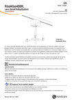
1
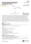
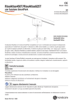
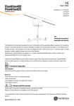
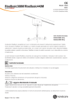
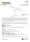
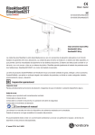
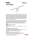
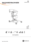
RiseAtlas625M,
User Manual - English
with QuickTrolleySystem
SystemRoMedic
TM
50100059
SWL: 285 kg/625 lbs
RiseAtlas625M is a safe and easy-to-use stationary ceiling lift unit which can be used in all settings and in all types of
rooms, both on permanent rail systems and on portable, freestanding lift stands. When used with the appropriate lifting
accessories, RiseAtlas625M provides secure, comfortable and individually adapted lifting of users in connection with
seated or horizontal transfers to and from the bed, wheelchair or toilet. RiseAtlas625M offers a large lifting area and
the possibility of both very low and very high lifting, making it an excellent solution also for lifting from the floor and for
gait training and standing training. RiseAtlas625M can also be used for convenient transfer of users from one room to
another. RiseAtlas625M is manually transferred along the rail (M for manual) and features Handicare’s unique
SystemRoMedic™ QuickTrolleySystem. This model is fitted with a quick release trolley which readily allows for
dismantling of the ceiling lift unit from the rail.
Functional inspection
Visual inspection
Inspect lift functions regularly. Check to ensure that product is free from damage.
Before use
Ensure that the product is correctly mounted in the trolley.
Check rail end stops.
Check sling bar connection and safety latch function.
Check lifting movement.
Inspect the lift for signs of wear and damage.
Check the hand control cable for signs of wear.
Check to ensure that hand control markings coincide with lift functions.
Check battery charge level.
Always read the user manual
Always read the user manuals for all assistive devices used during a transfer.
Keep the user manual where it is accessible to users of the product.
Under no circumstances may the lift be used by persons who have not received instruction in the operation of the lift.
It is strongly prohibited to modify the original product.
Manual nr: 705-En Ver. 5 150504
Table of contents
Installation....................................................................................3-10
- Unpacking and check............................................................................. 3
- Transport and storage............................................................................. 3
- Installing the lift unit............................................................................... 3
- Emergency stop strap............................................................................. 4
- Charging the lift unit............................................................................ 5-8
- Using QuickTrolleySystem....................................................................... 9
- Different rail systems.............................................................................10
- Final inspection.....................................................................................10
Using the product....................................................................11-16
- Important information ...........................................................................11
- Before use............................................................................................11
- Safe working load.................................................................................12
- Description of functions and symbols......................................................13
- Hand control.........................................................................................13
- Information panel..................................................................................14
- Preventive service maintenance..............................................................14
- Emergency stop ....................................................................................15
- Electrical emergency lowering................................................................15
- Manual emergency lowering/raising........................................................15
- Trouble-shooting...................................................................................16
Accessories.....................................................................................17
Maintenance...................................................................................18
Technical information
................................................................19
- Detailed description...............................................................................19
2
M A N U A L SystemRoMedic
TM
Installation
Unpacking and check
With RiseAtlas, the following is included in the package:
1 RiseAtlas lift unit
1 Trolley
1 Hand control
2 Manuals - User manual, Assembly instructions for fuse
1 Charger station
1 Manual emergency lowering key
1 Label (QuickTrolleySystem)
1 Label (Parking for end point charging)
Check to ensure that no components are left in the packaging.
Inspect the lift unit for signs of damage.
Transport and storage
Before shipping, the fuse is removed to prevent battery discharge during transport or long-term storage.
Install the fuse in the lift unit according to the accompanying instructions.
Installing the lift unit
NOTE! The lift unit and carriage must be installed and inspected by authorized personnel according to instructions issued
by Handicare AB. Periodic inspection must be performed at least once a year. Use only original spare parts. Service and
maintenance must be performed according to instructions in the user manual.
The lift must be charged for at least 3 hours before it is used for the first time. The lift unit is shipped with the fuse
removed. Prior to installation the cover is removed and a 20A fuse is inserted. The fuse is packed in a bag. As standard,
the lift is factory pre-set for charging at a charger station. When installing the lift unit for in-rail charging on the rail system,
the system must be fitted with charger rails. Exercise caution when installing the lift unit, so that the charger wheels do
not come in contact with the rail, since this may cause short-circuiting. Incorrect installation may cause short-circuiting
and damage the charger.
Alteration of the charging method must be performed by authorized
personnel according to instructions issued by Handicare AB.
SystemRoMedic M A N U A L
TM
3
Emergency Stop Strap
When the lift is correctly installed in the trolley system, the emergency
stop strap needs to be adjusted. The emergency stop strap is cut at a
height where the strap doesn´t interfere with a normal lifting situation but
at the same time is easily reached by all users.
The strap is cut with scissors and singed at the end as to prevent unravel.
Handicare recommends a height of 180 cm/70 inches above the floor.
180 cm
Assembly of charger unit
The following is included in the charger station package:
•
Holder
•
Charger cup
Charger cable (EU, UK, US connectors included)
(fixtures between charger station and wall/freestanding rail not included)
Charger station
a) Secure holder to charger station on wall/freestanding rail system. Recommended
height is 110-120 cm from floor.
b) Mount the charger cable. If necessary mount the cover for the charger.
c) Connect the accompanying hand control to the charger station and the hand
control cable to the lift unit. Check charger function.
4
M A N U A L SystemRoMedic
TM
Charging the lift unit
RiseAtlas can be used with three different charging systems:
1. Charger station for charging via hand control (Standard)
2. In-rail charging (Accessory)
3. End-point charging (Accessory)
RiseAtlas is charged with a charger unit that is connected to the charger cables via a DC outlet. The charger should be
kept in an appropriate location. Note that the charger is a separate unit and can be easily mistaken for another charger.
Ensure that the correct charger is used, see Technical information. For assembly instructions, see Assembly of charger
unit.
1) The lift unit is charged via a wall-mounted charger station. Place the hand
control in the charger station. The charging lamp on the lift unit indicates charging
for 15 minutes after being activated. Charging continues until the battery is fully
charged.
2) For in-rail charging, the lift unit is always kept charged, which means that it can
be left anywhere on the rail and will charge automatically.
3) For end-point charging, the lift unit is placed at the charger station at the end
of the rail. If the rail system is of the traverse type, the secondary rail is placed at
the end of the primary rail at which the charger station is located. Check to ensure
that the battery symbol on the lift unit lights up.
SystemRoMedic M A N U A L
TM
5
Alternative 2: In-rail charging (Accessory for article number 50100059)
If the in-rail charging option is chosen, the lift unit must be fitted with a charger contact (70200062) and charger rails
before installation. The charger that is included with the lift unit is used.
Alteration of the charging method must be performed by authorized
personnel according to instructions issued by Handicare AB.
1) Set the charging points for in-rail charging. To set the charging points for in-rail charging, remove the spring pins that
hold the charger plate in place. Then, the dip switch on the circuit board is set for the desired charging function.
2) Check to ensure that the charger plate springs in and out when pressure is applied to the charger plate, see
fig 2.
3) Check to ensure that charger rails have been installed (installation of charger rails is described in the installation
manual for MilkyWay).
4) Guide the lift unit onto the rail so that the plus on the charging point is on the right side, according to fig 3.
5) Connect the red cable to the charger rail on the right side, the charger plate’s plus side (positive), and the black cable
on the left side (negative), according to fig 4.
6) Install the end-stop on the rail.
1
2
NOTE! No spring pin
3
+
+ Plus
4
6
M A N U A L SystemRoMedic
TM
Alternative 3: End-point charging (Accessory)
If the end-point charging option is chosen, the lift unit must be fitted with a charger contact (70200062). The charger that
is included with the lift unit is used.
1)Check to ensure that the charging points are set for the charger station; the charger plate is secured with the spring
pins, see fig 1.
2)Check to ensure that the charger plate springs in and out when pressure is applied to the charger plate, see fig 2.
3)Guide the lift unit onto the rail so that the plus on the charging point is on the right side, according to fig 3.
4)Mount charger contacts according to figure 4. NOTE! Push the charger contact (A) in about 50 mm if only a stop bolt
is used. When an adjustable end-stop is used, the charger contact is pushed in about 90 mm.
5)Affix the accompanying screws for charger contacts, see fig 5 (B).
6) Connect the red cable to the charger contact on the right side, the charger plate’s plus side (positive), and the black
cable on the left side (negative), according to fig 6.
7) Install the end-stop on the rail.
1
2
3
Spring pin
+
+ Plus
+
B
4
+
-
A
5
+
6
+
-
SystemRoMedic M A N U A L
TM
7
Battery status, charger station
•
The battery symbol lights green when battery capacity exceeds 50 %.
•
If the battery symbol blinks orange when the lift is started, the battery needs to be charged.
•
If the battery symbol lights orange and a beep is heard when the lift is run up, the battery needs to be
charged immediately.
•
When the lift unit is started the battery symbol lights up for 2 seconds to indicate the current battery status.
•
6 seconds after every operation the battery symbol lights for 2 seconds to indicate the current
battery status. Only hand control charging or end point charging mode.
Charging indication (hand control charging and end point charging)
When the hand control is placed in the charger station 2 beep sounds are heard and
the green light should stay on for 15 minutes.
Battery status, in-rail charging
The battery symbol lights green when battery capacity exceeds 50%.
When the lift unit is activated the battery symbol lights green for 15 minutes.
If the battery symbol and the book symbol blink orange when the lift unit is started, the circuit for the charging
system has been broken and must be checked by a technician.
Active charging detection (In-rail charging)
After activation the lift unit will light the battery symbol for 15 minutes and after 4 minutes the charger should turn
on. If the lift unit is missing the charger it will start indicate after 4 minutes. Green 15 minutes after activation.
NOTE!
Use only the charger that is intended for the lift unit.
For maximum service life, charge batteries regularly. Do not allow the battery charge level to fall below 25%
(orange symbol on control panel).
Emergency stop must not be activated during charging.
8
Batteries may only be replaced by authorized personnel.
M A N U A L SystemRoMedic
TM
Using the QuickTrolleySystem
1. Check to ensure that the lift unit’s emergency stop is activated by pulling the emergency stop strap.
2. Place the lift unit on the rail by inserting the T-fitting (upside down) from the trolley into the hole on the top of the lift unit.
3. Press up, and then rotate the lift unit 90 degrees to lock the T-fitting in the lift unit.
4. Click the locking clip into place.
5. Check to ensure that the lift unit is secured to the trolley and that it can be moved along the rail. The lift unit must be
able travel freely on the rail system without obstruction and there must be no risk of the lift unit colliding with any objects
in its path.
6. To remove the lift unit from the rail, perform the above procedure in reverse.
Images 1-5: Locking the trolley to the lift unit.
SystemRoMedic M A N U A L
TM
9
Different rail systems
The choice of rail system is determined by the lifting needs at hand.
Rail system with full room coverage,
Basic rail systems,
above bathroom wall
with curves and turn table
Freestanding lift stand
Final inspection
• The RiseAtlas lifting unit must be installed and first-time inspected by authorized personnel (inspector) in accordance
with the installation instructions provided by Handicare AB. Periodic inspection of the equipment should be undertaken
at least once a year. Original spare parts should be used and service/maintenance of the equipment should be in
accordance with the user manual.
• Check to ensure that no parts have been left in the packaging.
• Check to ensure that the lift has no signs of damage from transportation.
• Check to ensure that the emergency stop is functioning by pulling the emergency stop strap, and then pressing the UP
or DOWN button. If nothing happens, the emergency stop is working properly.
• Check the entire length of the strap for signs of damage and inspect seams for wear. Press the up button and run the
strap all the way up. Then, press the down button and run the strap all the way down.
• Test lift function by lifting a person (not a user) using an approved lifting sling. At the same time, check both the user
manual and electrical emergency lowering function with someone in the lift. See section on Emergency lowering.
• Check to ensure that the rail system is equipped with end stops.
• Check the hand control cable for signs of wear.
• Check to ensure that hand control markings coincide with lift functions.
• The user/attendant shall always pay attention to and report any unusual noises or vibration of the equipment.
NOTE!
Before the lift is used for the first time it must be charged for at least 3 hours. See section on charging the lift.
RiseAtlas is shipped with the emergency stop activated to prevent battery discharge during transport or long-term
storage.
Always keep the key for the emergency lowering close to the lift.
All personnel who use the lift must be informed of where the key is kept.
10
M A N U A L SystemRoMedic
TM
Using the product
Important information
• The user/attendant shall be trained professional with thorough understanding of the equipment and lifting of disabled
persons. It is important that proper accessories and techniques are used by the user/attendant and it is also very
important that a user never is left unattended in a lifting situation.
• Warranty does only apply if repairs or alterations are made to the lift by personnel who are authorized.
• RiseAtlas must not come in direct contact with water.
• RiseAtlas must not be charged in a wet room.
• To ensure optimal function, the lift must be inspected regularly. See section on Maintenance.
• Under no circumstances may safe working load be exceeded. See section on Technical information and the product
label on the lift.
• Lifting accessories must be properly trial fitted and tested in relation to the user’s needs and functional ability.
• Particular care must be taken when using the equipment near strong sources of interference, such as diathermy
apparatus, so that e.g., diathermy cables and similar equipment are not placed near the device. When in doubt, consult
your equipment technician or the supplier.
Before use
- Ensure that the product is correctly mounted in the trolley.
- Check rail end stops.
- Check sling bar connection and safety latch function.
- Check lifting movement.
- Inspect the lift for signs of wear and damage.
- Check the hand control cable for signs of wear.
- Check to ensure that hand control markings coincide with lift functions.
- Check battery charge level.
SystemRoMedic M A N U A L
TM
11
Safe working load
Different products on the same lift system (lift unit, lifting sling and other lifting accessories) may have different safe
working loads. The lowest allowable safe working load always determines the safe working load of the assembled
system. Always check the safe working loads for the lift and accessories before use. Contact your dealer if you have any
questions.
Description of functions and symbols
RiseAtlas has many built-in functions. Each function is described in the respective section in the user manual, or in the
user manual for the respective accessory. Below is a brief description of the functions that are available for caregivers
and users.
May not be discarded in
Read user manual
domestic waste
Medical Device Class I. The product
Type B, according to the
complies with the requirements of the
degree of protection against
Medical Devices Directive 93/42/EEC.
electric shock.
The device is intended for indoor use.
Class lI equipment
Conforms to ISO 10535:2006 with
Always Read The User Manual
ANSI/AAMI ES 60601-1:2005 and
is certified to ISO 10535:2006 with
CSA-C22.2 No. 60601-1:08
Symbols on the product
Battery status
Emergency stop
The lift requires service or
Directional indication, transfer
maintenance
motor
Overload
Warning!
Read the user manual
Read user manual
12
M A N U A L SystemRoMedic
TM
Hand control
Connection of hand control to lift unit
The outlet for the hand control is under if the lift unit, fig 1. Connect the hand control firmly.
Raising/lowering
The buttons with the black arrows raise and lower the lift strap. Raising/lowering is interrupted
as soon as pressure on the buttons is released, fig 2. The lift unit can also be activated with
the buttons for raising/lowering.
1
ON/OFF via hand control
The hand control is equipped with a green button (ON) to activate the lift unit and a button
(OFF) to shut it off (3). The lift unit automatically shuts off after 15 minutes of inactivity. Normally,
the lift can be activated via the green (ON) button before use.
2
Night light
RiseAtlas is equipped with night lighting, which will be activated by pressing and holding the
ON button on the hand control for 3 seconds. The LED lamp lights for 15 minutes if it is not
inactivated via the OFF button on the hand control.
Activate/start the lift unit
The lift unit is activated by pressing the green button (ON) or the Up- or Down-button on the
hand control. When this is done the battery symbol on the lift unit´s information display is lit for
3
ON
OFF
2 seconds, showing the current battery status. If the battery symbol does not light and the lift
unit is not activated, check that the emergency stop is not activated (pulled out).
Active safety
RiseAtlas has a built-in slack strap switch requiring that, in order to be manoeuvered up or
down, RiseAtlas must be loaded with at least 2 kg or its own weight. This is a safety feature
that prevents a slack lift strap from being winded in or out from the lift unit causing a short fall
when next in use.
RiseAtlas automatically stops if the lift strap is unloaded, for example if it is lowered onto a
table.e.g., when the sling bar is lowered to a bed. If this happens, the lift strap must be
manually stretched in order to be manoeuvered up or down.
If the lift strap is twisted when lifting upwards, the lift unit automatically stops and can only be
manoeuvred down. In order to save battery the lift unit automatically turns off after 15 minutes
of inactivity.
Tension release
When the top limit switch has been activated it will reverse the strap 5 mm to clear the
pressure from the switch. This action will take place after the up button has been deactivated.
SystemRoMedic M A N U A L
TM
13
Information panel
On the control panel at the bottom of the lift unit there are several symbols. The symbols lights up
when a function is activated. More information on each function is given below, and under chapter
Trouble-shooting.
Battery status
Battery status is indicated after 6 seconds when a lift with end point charging is activated, and for
15 minutes if the in-rail charging option is used.
Service/maintenance
Information concerning service and maintenance. This symbol is activated once the lift unit has
been used for 12 months.
Overload protection
RiseAtlas is equipped with overload protection, which prevents the lift from lifting more than the
maximum rated load if this happen. A symbol for overload and a warning triangle light up and a
signal is heard. If this symbol is activated, the user is too heavy.
Read user manual
Often, the book symbol will light up at the same time as another symbol lights up, indicating that the
user should read the user manual before using the lift again.
Night light
RiseAtlas is equipped with night lighting, which will be activated by pressing and holding the ON
button on the hand control for 3 seconds. The LED lamp lights for 15 minutes if it is not inactivated
via the OFF button on the hand control.
Warning
The warning triangle is activated, prompting the user to read the user manual. Often, the warning
triangle will light up at the same time as another symbol lights up, indicating that the user should
read the user manual before using the lift again. Normally, a technician must be contacted when this
symbol is activated.
Preventative service/maintenance
The symbol for service/maintenance lights up automatically when the lift unit has been used for 12 months.
Contact an authorized Handicare service technician for maintenance and resetting.
14
M A N U A L SystemRoMedic
TM
Emergency stop
To activate emergency stop funktion: Pull the red emergency stop strap firmly, fig 1, and then
release.
1
To reset: Push the plastic button that holds the red strap in place upward until it clicks,
see fig 2.
When the emergency stop funtion is activated, a red indication is visible, fig 1, above
emergency stop strap and its white plastic button.
If the emergency stop strap is held down constantly, electrical emergency lowering will be activated. When the strap is released, the lift will stop.
Electrical emergency lowering
If the hand control is not functioning, electrical emergency lowering can be activated by holding the emergency stop strap down, fig 1. Lower the user to a safe height and location.
2
Electrical emergency lowering may only be used if the hand control is
malfunctioning.
The electrical emergency lowering device feeds out the lift strap for as long as the emergency
stop strap is held down. Ensure that the lowering motion is activated. Otherwise, electrical
emergency lowering must be stopped. Always ensure that emergency lowering is done in an
appropriate location.
To reset: Press the plastic button that holds the red strap in place upward until it clicks, see fig
3
2.
Manual emergency lowering/raising
Remove the plastic cover on the same side as the emergency stop strap, fig 3. On the inside
of the cover there is an Allen key. Place the supplied Allen key in the hole as indicated, fig 4.
Turn it counter-clockwise to lower and clockwise to raise the sling bar. Always ensure that
emergency lowering is done in an appropriate location.
4
NOTE! Lowering is very slow.
Re-setting manual emergency lowering/raising: Contact an authorized Handicare service technician. Do not use the lift unit.
Allen key
SystemRoMedic M A N U A L
TM
15
Trouble-shooting
If lifting motion cannot be activated, check to ensure:
- that the emergency stop is not activated; on certain models, the emergency stop symbol lights up;
- that the lift unit is switched on (ON) via the hand control (a signal is heard);
- that the hand control is properly connected and pressed in securely; disconnect, and then replace it and press it in
securely;
- that the lift unit is not in the charging position; the lift unit is blocked for use when it is in the charging position;
- that the battery is charged;
- that the charger has a power supply; the charging lamp on the charger unit should light up when the lift unit is placed
in the charging position;
- that load is applied to the lift strap.
If the lift unit is not working properly, contact your Handicare dealer.
If the lift cannot be run all the way up to stop, check to ensure:
- that the overload symbol is not activated;
- that the battery symbol does not indicate low battery charge level.
If the lift cannot be run down, check to ensure:
- that load is applied to the lift strap;
- that the battery symbol does not indicate low battery charge level;
- that the directional indicators on the buttons, arrow up and arrow down, are correct.
If unusual sounds are heard:
- try to locate the source of the sound. Take the lift unit out of service and contact your Handicare dealer.
Symbol indication:
The symbol indicates that the lift unit must be inspected. Contact your dealer.
The symbol lights up after 6-12 months.
Indicates battery charge status.
Emergency lowering battery
- Light up when accessory with 9V battery are connected and the power in the 9v battery is low
(need to be changed). Both symbols will light amber. Sound should indicate (pip) every minute.
In-rail charging
- When book symbol light and the battery symbol flashes the charging function is not functioning.
No contact with the charger.
Overload protection
- Prevents the lift from lifting more than the maximum load. If this happens A symbol for overload
and a warning triangle light up (amber) a signal is heard. If this symbol is activated, the user is too
heavy.
16
M A N U A L SystemRoMedic
TM
Accessories
QuickTrolley625, article no.: 70200063
QuickTrolley625-90, article no.: 70200064
Cover to charger, article no.: 50400066
In-rail/end point charging, article no.: 70200062
IR remote controlling, article no.: 70200065
9V battery and cable, article no.: 70200047
Software for diagnostics, article no.: 70200048
Parking Placard, article no.: 50400048
Lifting slings
Handicare’s SystemRoMedic™ line includes a wide range of functional and comfortable,
high-quality lifting slings that are adapted for all types of lifting and for users with different
needs. The lifting slings are available in several materials and in sizes ranging from XXS to
XXL. There are also special lifting sling models in XXXL and XXXXL for extremely large and
heavy users. All models are safe and very easy to use.
Sling bars
SlingBar is a two-point aluminium sling bar available in three variants with different width. All
variants of SlingBar have safety latches which prevent the sling straps from creeping out of
the sling bar and all variants are for users weighing up to 300 kg/660 lbs.
To get more room in a lifting sling when using SlingBar two-point sling bar, SlingBarSpreader
M side bars can be used as an accessory. SlingBarSpreader M open up the lifting sling and
provide for a more reclined position.
1
2
3
4
5
6
A
A
B
B
SlingBar XS, (250 mm) article no.:70200071
SlingBar S, (350 mm) article no.: 70200001
SlingBar M, (450 mm) article no.: 70200002
SlingBar L, (600 mm) article no.: 70200003
SlingBarSpreader M, article no.: 70200042
C
C
DRAWN
NAME
DATE
hc-mabr
2010-10-14
APPROVED BY
STATUS:
D
-
COMMENTS:
Unless otherwise stated,
general tolerances
according to ISO 2768-m
TITLE
-
SIZE
A4
DWG. NO.
REV.
-
-
MATERIAL:
1023 Carbon Steel Sheet (SS)
SCALE:2:1
1
2
WEIGHT:
158.68 g
SHEET 1 OF 1
3
BariBar, article no.: 70200072
SwiftHook for sling bar, article no.: 70200008
StretcherBar, article no.: 70200006, and StretcherSling, article no.: 46502007, for lifting in a
supine position.
Sling bar RFL X4, four-point sling bar, Article no.: 70200017
Scales
Handicare’s SystemRoMedic™ scales Charder MHS2500 are used together with stationary
or mobile lifts for weighing of users.
Article no.: 70100002 (300 kg/661 lbs)
Article no.: 70100003 (400 kg/881 lbs)
Assistive devices for positioning
Handicare’s SystemRoMedic™ line includes a wide range of functional, comfortable,
high-quality assistive devices for positioning that can be adapted for different types of lifting
and for users with different needs.
SystemRoMedic M A N U A L
TM
17
Maintenance
The lift must undergo thorough inspection at least once per year. Inspection must be performed by authorized personnel
and in accordance with Handicare’s service manual.
Repairs and maintenance may only be done by authorized personnel using original spare parts.
Spent batteries are to be left at the nearest recycling station. Spent batteries can also be returned to
Handicare or a Handicare dealer for recycling.
Cleaning/disinfection
If necessary, clean the lift with warm water or a soap solution and check that the castors are free from dirt and hair. Do
not use cleaning agents containing phenol or chlorine, as this could damage the aluminium and the plastic materials. If
disinfection is needed, 70 % ethanol, 45 % isopropanol or similar should be used.
Storage and transportation
If the lift is not to be used for some time or e.g., during transport, we recommend that the emergency stop button be
pressed in. The lift should be transported and stored in -10 ° C to + 50 ° C and in normal humidity, 30% -75 %. The air
pressure should be between 700 and 1060 hPa. Let the lift reach room temperature before the batteries are charged or
the lift is used.
+50
+50 °C
ºC
-10
-10 °C
ºC
kPa
70070hPa
106 kPahPa
1060
75%
75%
30%
30%
Service agreements
Handicare offers service agreements for maintenance and regular testing of your lift unit. Contact your local Handicare
representative.
Serial number
18
M A N U A L SystemRoMedic
TM
Technical information
Lifting speed: :
3,9 cm/s (5,0 cm/s), 1.5 inch/s (2.0 imch/s) with (without) load
Batteries:
24 VDC (20st 1,2VDC) 3,2 Ah. NIMH20XA3200
Charger IN:
Mascot 2215 100-240VAC/ 50-60Hz Max 0,9A.
Charger OUT:
41 VDC/ ±0,3 Max 0,9A
Lift motor:
24VDC
Motor cover:
Flame-resistant ABS plastic
Sound level:
Unload: 55 dB, Max load: 57 dB
Hand control:
Electronic
Emergency lowering:
Manual and electrical
Lifting range:
240 cm/95 inch
Lift weight:
7,2 kg, 15,9 lbs
IP class, lift unit:
IP 20
IP class, hand control:
IP X4
Lift measurements:
266 x 151 x 156 mm, 10.5” x 5.9” x 6.1”
Intermittent operation:
Op 10/90, active op. max. 2 min. Out of a time of 100, active time must be less than
10, though not more than 2 min.
Expected service life:
10 years
Pressure hand control:
4N
SWL
285 kg, 625 lbs
Medical Device Class I. The product complies with the requirements of the Medical Devices Directive 93/42/EEC.
Detailed1 description
2
3
4
REV.
DESCR
64
1. Outlet for hand control
A
2
2. Hand control
3. Lift strap
4. Emergency stop and electrical
212,2 272,5
emergency lowering
5. Manual emergency lowering/raising
5
6. Control panel
1
3
B
6
SystemRoMedic M A N U A L
TM
RiseAtlasM Q-models
4
Basic rail system
19
SystemRoMedic
TM
Simple solutions for great results
SystemRoMedic™ is the name of Handicare’s unique easy transfer concept, the market’s widest and most
comprehensive range of clever, easy-to-use and safe transfer and lifting aids designed to make life easier, both for the
user and for the caregiver. SystemRoMedic™ is a complete solution that provides for the majority of patient transfer or
manual handling requirements. From the simplest to the most complex scenarios, from the lightest to the heaviest. The
concept encompasses assistive devices for four different categories of transfers:
•
Transfer, assistive devices for manual transfers of users between two locations.
•
Positioning, assistive devices for manual repositioning of users within the same location.
•
Support, assistive devices for mobility support e.g., during sit-to-stand or gait training.
•
Lifting, assistive devices for manual and mechanical lifting of users.
Improved work environment, improved quality of care and cost savings
The philosophy behind SystemRoMedic™ is focused on the prevention and reduction of occupational injuries while
allowing users to experience a greater sense of independence and dignity. Through a unique combination of training and
a complete range of efficient transfer aids, SystemRoMedic™ offers improvement of both work environment and quality
of care and, at the same time, achieves significant cost savings.
Always make sure that you have the correct version of the manual
The most recent version of all manuals are available for downloading at/from our website; www.handicare.com.
For questions about the product and its use
Please contact your local Handicare and SystemRoMedic™ representative. A complete list of all our partners with their
contact details can be found on our website; www.handicare.com.
Handicare offers solutions and support to increase the independence of disabled or elderly people as well as to improve the convenience of those who
are caring for them.
The Handicare Group is one of the leading healthcare companies in Europe with its own manufacturing organizations and sales companies
in Norway, Sweden, Denmark, Germany, the Netherlands, Great Britain, France, China, Canada and the USA. Handicare’s products are also
distributed by partners in more than 40 countries worldwide. Our wide range of high-quality products includes various manual and power
wheelchairs, seating systems, scooters, a complete easy transfer system and other patient handling aids, stairlifts, car adaptations, rise and
recline chairs, and bathing and toileting products.
Handicare AB
Maskinvägen 17
SE-972 54 Luleå , SWEDEN
Tel: +46 (0)8-557 62 200
Fax:+46 (0)8-557 62 299
E-mail: [email protected]
www.handicare.com
Handicare AB is quality and environmentcertified in accordance with ISO 9001, ISO14001 and ISO 3485.