1
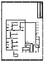
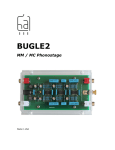
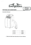
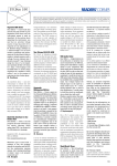
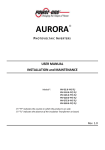
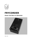
HAGERMAN
T E C H N O L O G Y
Cornet
Phono Preamp Kit
User’s Manual
Cornet Phono Preamp Kit Manual
2
Warnings
This product uses dangerous and potentially lethal voltages. Extreme care must be taken
while assembling this amplifier and should only be attempted by a skilled technician.
The instructions in this manual are a suggested guide only and no liability is assumed by
Hagerman Technology LLC.
Copyrights & Trademarks
© Copyright Hagerman Technology LLC 2002 – 2007. All rights reserved. No part of
this document may be photocopied, reproduced, or translated to another language without
the prior written consent of Hagerman Technology LLC.
Disclaimer
The information contained in this document is subject to change without notice.
Hagerman Technology LLC shall not be liable for errors contained herein or for
consequential damages in connection with the furnishing, performance, or use of this
material. See Chapter 6 for warranty information.
Cornet Phono Preamp Kit Manual
3
1 Before You Begin
Description
Congratulations! You have just purchased one of the highest performance-per-dollar
audiophile products available. The Cornet was designed to be a simple phono stage
capable of achieving excellent sound quality. The circuit topology consists of common
cathode class-A gain stages, passive equalization, and cathode follower output buffers.
Vacuum tube rectification for the high voltage provides a gentle turn-on without the need
for muting circuits. The moderate gain accommodates all moving magnet and high
output moving coil cartridges.
Features
•
•
•
•
•
•
All vacuum-tube signal path
Pure class-A amplifier stages
No feedback
Cathode follower low impedance outputs
Vacuum tube B+ rectification
Constant current sinks
Tools
This is a kit product and construction should only be attempted by skilled electronic
technicians (refer to warnings at the front of this manual). You will need an array of shop
tools and a good soldering iron. If you are at all unsure of this, send it back!
Cornet Phono Preamp Kit Manual
4
2 Parts to Buy
Kit
The Cornet kit does not need to be built as specified. You may make any circuit and
component changes you wish (but you had better know what you’re doing). Feel free to
substitute vacuum tubes or capacitor types. A recommended parts list is given below.
Parts List
This parts list is for a stock 43dB RIAA MM phono stage. Parts should be ordered
directly from www.digikey.com and www.tubesandmore.com (AES). Included with
your “box/2” kit are:
•
•
•
•
•
•
•
•
•
•
Cornet circuit board (1)
AC voltage select board (1)
Chassis (1)
#6 x ¼” self-tapping screws (20)
Terminal ring (1)
#10 x 1” screws (4)
#10 nuts (8)
#10 rubber washers (4)
#8 x 1.75” screws (4)
#8 nuts (4)
Upgrades
Signal coupling capacitors can be improved, substitute AES #CAUD1-450 and #CAU1450 for C5 and C6 respectively, two each.
5
Cornet Phono Preamp Kit Manual
Component
Qty
DigiKey
47uF 450V
10,000uF 10V
470uF 10V
1uF 630V PP
100nF 400V PP
47nF 630V PP
1nF 630V PP
10nF 250Vac
1N5821
MJE340
Heat Sink
Power Cord
Ground Jack
Standoffs 0.75”
Feet
AC Input
Fuse
Switch
Res. 220 1W
5
4
2
6
2
2
2
2
4
2
2
1
1
10*
4
1
5*
1
14
493-1461-ND
493-1275-ND
Res. 910 1W
Res. 3k3 1W
Res. 6k8 1W
Res. 10k 1W
Res. 47k 1W
Res. 150k 1W
Res. 330k 1W
Res. 1R8 5W
RCA Jack, R
RCA Jack, W
Transformer
Socket 8 pin
Socket 9 pin
12AX7
12AU7
5AR4
8
2
5
4
2
6
4
1
2
2
1
1
3
2
1
1
* Minimum quantity.
AES
References
C2, Cx, C10
C13, C14, C15, C16
Cx
C1, C3, Cx
C5
C7
C8
C9, C20
D1, D2, D3, D4
PF4105-ND
PF4104-ND
P3517-ND
P3497-ND
P11423CT-ND
1N5821DICT-ND
MJE340G-ND
HS216-ND
Q120-ND
J587-ND
4818K-ND
SJ5523-0
Q205-ND
F2419-ND
SW620
220W-1-ND
R6, R7, R8, R10, R11,
R12, Ry
R15, R17, Rx, Rz
R23
R2, R13, R20
R1, R9
R14
R3, R5, R16
R4, R19
R21
910W-1-ND
3.3KW-1-ND
6.8KW-1-ND
10KW-1-ND
47KW-1-ND
150KW-1-ND
330KW-1-ND
1.8W-5-ND
S-H267R
S-H267W
P-T370BX
P-ST8-193
P-ST9-214
12AX7
12AU7
5AR4
V4
V1, V2, V3
Cornet Phono Preamp Kit Manual
6
3 Assembly
Circuit Board
Solder the sockets onto the backside of the circuit board. This is the side without silk
screening. Make sure the orientation of the octal socket is correct! Then install the six
standoffs (on socket side).
Install all of the resistors and solder in place (except R15s). Use the guide in the back of
this manual. Don’t forget to clip leads. Repeat for the diodes, signal capacitors, and
finally the large electrolytic capacitors. Make sure the polarity of the electrolytics is
correct (“+” is positive polarity). Install R15s as shown below, using the ground
connection of the socket’s pin 9. Use a wire for R22. C11 and C12 are unused, but you
can add small 100nF caps if you desire.
Add heat sinks to MJE340 transistors and solder in place as shown. The heat sinks do not
attach to board. The metal part of the transistor faces away from the mickey mouse ears.
Cornet Phono Preamp Kit Manual
7
Finally, add short lengths (about 2”) of signal wire to the input and output connections on
the circuit board, including ground.
Chassis
Remove from plastic. Apply rubber feet to bottom panel, put aside. Install grounding
jack with ring terminal on inside. Enlarge the RCA jack holes to 0.375” and install RCA
jacks with their insulating washers. White pair goes on left, red on right. Insert power
switch and ac input connector.
Mount the transformer with #10 screws, with washers between mounting tabs and chassis
(do not tighten yet), with primary wires towards the outside. Inside the chassis, slide the
AC voltage select board onto the screws. Put on nuts loosely. Ok, now tighten down the
screws from above, securing the transformer in place. Do not over tighten or the washers
will deform excessively. Tighten the nuts holding the board down on the inside. Finally,
solder C1 (10nF 250Vac cap) into place.
Replace the #8 bolts holding the transformer together with the supplied stainless steel
types (do not remove insulators). Mount circuit board inside.
Cornet Phono Preamp Kit Manual
8
Wiring it up
You can optionally use #1285K-ND solder tabs and #A27804-ND crimp terminals for
wiring to the circuit boards. This allows you to plug and unplug as in the photo above.
Normally, you can solder wires straight to the boards.
Connect transformer secondary wires to the cornet circuit board. The violet wire is
unused. Cut it short and insulate so that it touches nothing. Connect the primary wires to
ac voltage select board. Refer to ac voltage chart on schematic for proper hookup.
Add ground wire from ac input connector to voltage select board. Add neutral wire. Add
wire from line to power switch, and then another from there to voltage select board.
Refer to schematic. You can use tie wraps or tape to bundle wires together. Keep
primary wires separated from secondary. Trim input, output, and ground signal wires to
an appropriate length, and solder to their respective RCA jacks and ground terminal.
Install tubes and fuse. Unit is now ready for testing.
Cornet Phono Preamp Kit Manual
9
4 Testing & Installation
Testing
Double-check all of your work before applying power. Wear safety glasses. Turn on the
power and check for smoke. If all goes well, after 60 seconds of warm-up, check to make
sure the power supply and tube voltages are as specified on the schematic. Check plate
voltages on the 12AX7s, as they should be around 140V. If all is well, power down and
install bottom cover.
Connections
Connect the Cornet just like any other phono stage. The input and output jacks are RCA
types. Make sure the ground lead from the turntable is connected to the grounding screw
between the input jacks.
Cornet Phono Preamp Kit Manual
10
5 Specifications
The following specifications are subject to change without notice.
Item
Specification
Gain
Input Impedance
Output Impedance
RIAA Response
Bandwidth (-3dB)
Distortion
SNR
Overload
Size (PCB)
Size (Chassis)
Input Power
Tube Compliment
43dB
47k ohm plus 40pF
1k ohms
+/-1dB from 25Hz to 25kHz
15Hz to 30kHz (minimum)
0.02% @1kHz
75dB ref 5mV A-weighted
250mV @1kHz
5.25” x 8.50”
12” x 8”
33W
12AX7 (ECC83) x 2, 12AU7 (ECC82) x 1, 5AR4 x 1
Cornet Phono Preamp Kit Manual
11
6 Warranty & Service
Warranty
Hagerman Technology LLC warrants this product free of defects in materials and
workmanship for 10 years (90 days for tubes). If you discover a defect, Hagerman
Technology LLC will, at its option, repair or replace the product at no charge to you
provided you return it during the warranty period, transportation charges prepaid to
Hagerman Technology LLC. This warranty does not apply if the product has been
damaged by negligence, accident, abuse or misuse or misapplication, has been damaged
because it has been improperly connected to other equipment or has been modified
without the express written permission of Hagerman Technology LLC. This warranty is
limited to the replacement or repair of this product and not to damage to equipment of
other manufacturers.
Any applicable implied warranties, including warranty of merchantability, are limited in
duration to a period of the express warranty as provided herein beginning with the
original date of purchase and no warranties, whether express or implied shall apply to the
product thereafter.
Under no circumstances shall Hagerman Technology LLC be liable for any loss, direct,
indirect, incidental, special, or consequential damage arising out of or in connection with
the use of this product.
Service
Refer to Chapter 4 for troubleshooting information. If the problem persists, contact
Hagerman Technology for service at http://www.hagtech.com.
Hagerman Technology LLC
PO Box 26437
Honolulu, HI 96825 USA
808-383-2704 (voice)
808-394-6076 (fax)
1
2
3
4
5
A
A
N
E
L
BRN
B
B
POWER
110V
NC
L
NC
N
NC
L
NC
N
NC
NC
L
N
NC
NC
L
N
Blu
Blu/Yel
Brn/Yel
Brn
Blk
Blk/Red
Wht/Blk
Wht
C
C1
10nF
AC
L
NC
NC
N
L
NC
NC
N
120V
NC
NC
S
N
NC
NC
L
S
200V
AC VOLTAGE SELECT
100V
BLU
GRN
BRN
C
N
S
L
D
D
NC
S
NC
N
NC
L
NC
S
220V
S
NC
NC
N
L
NC
NC
S
240V
grn
wht
grn
yel
yel/blk
yel
red
vio
red/yel
red
grn/yel
370BX
wht/blk
blk/red
blk
brn
brn/yel
blu/yel
blu
E
E
(UNUSED)
Date:
Size
F
Friday, October 19, 2007
n/a
Document Number
Sheet
Cornet: AC Voltage Select
Title
P.O. Box 26437
Honolulu, HI 96825
Hagerman Technology LLC
F
1
G
G
of
1
B
Rev
1
2
3
4
5
1
2
3
4
5
J1
In
A
A
R14
47k
220
R12
grn
g/y
grn
yel
y/b
yel
red
r/y
red
2,7
3,8
1,6
C9
10nF
1kV
R20
6k8
1W
R15
910
B
10k
R9
V1A
12AX7
R3
150k
1W
300V
B
6
4
4
V4
5AR4
C1
1uF
400V
2
8
C7
47nF
250V
R13
6k8
1
3
2
D1-D4
1N5821
220
100nF
250V
R22
0R
R10
C5
C10
47uF
375V
R16
150k
R4
330k
1W
C2
47uF
C
C
C13
10mF
10V
R17
910
R21
C14
10mF
10V
1R8
5W
220
220
C8
1nF
250V
R23
3k3
R8
R7
10k
V2A
12AX7
R5
150k
1W
R1
C15
10mF
10V
6.3V
D
D
C16
10mF
10V
Rz
910
Qx
MJE340
Ry
220
220
R11
V3A
12AU7
R6
220
330V
9
H1
12AX7
4,5
Cx
470uF
10V
910
Rx
1uF
400V
C6
C3
1uF
400V
9
H2
12AX7
4,5
R19
330k
C4
47uF
E
J2
Out
6k8
R2
E
9
H3
12AU7
4,5
+43dB
Date:
Size
F
Friday, October 19, 2007
n/a
Document Number
Cornet: Phono
Title
P.O. Box 26437
Honolulu, HI 96825
Sheet
Hagerman Technology LLC
F
1
G
G
of
1
B
Rev
1
2
3
4
5