1
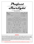
BUGLE2
MM / MC Phonostage
Made in USA
BUGLE2 Phonostage Kit
2
Copyrights & Trademarks
© Copyright Hagerman Audio Labs 2013. All rights reserved. No part of this
document may be photocopied, reproduced, or translated to another language
without the prior written consent.
Disclaimer
The information contained in this document is subject to change without notice.
Hagerman Audio Labs shall not be liable for errors contained herein or for
consequential damages in connection with the furnishing, performance, or use of this
material.
Warranty
Hagerman Audio Labs warrants this product free of defects in materials and
workmanship for a period of 10 years. If you discover a defect, Hagerman Audio
Labs will, at its option, repair or replace the product at no charge to you provided
you return it during the warranty period, transportation charges prepaid to
Hagerman Audio Labs. This warranty does not apply if the product has been
damaged by negligence, accident, abuse or misuse or misapplication, has been
damaged because it has been improperly connected to other equipment or has been
modified without the express written permission of Hagerman Audio Labs. This
warranty is limited to the replacement or repair of this product and not to damage to
equipment of other manufacturers. Any applicable implied warranties, including
warranty of merchantability, are limited in duration to a period of the express
warranty as provided herein beginning with the original date of purchase and no
warranties, whether express or implied shall apply to the product thereafter. Under
no circumstances shall Hagerman Audio Labs be liable for any loss, direct, indirect,
incidental, special, or consequential damage arising out of or in connection with the
use of this product.
Hagerman Audio Labs
PO Box 61911
Honolulu, HI 96839
808-383-2704 (voice)
www.haglabs.com
BUGLE2 Phonostage Kit
3
Description
Congratulations, you have just purchased one of the highest performance-per-dollar
audiophile products available! The Bugle2 was designed to be a simple yet flexible
phonostage capable of achieving very good sound quality comparable to far more
costly units. It is a second-generation circuit topology that uses low noise audio
opamps implementing passive split equalization filters and to provide a low output
impedance. Gain can be set for either 40dB or 60dB (suitable for MC cartridges).
Specifications
Item
Gain
Input Impedance
Output Impedance
Bandwidth
Distortion
Noise
Size
Power
Specification
40dB (MM) or 60dB (MC)
47k (MM) or 100 ohm (MC)
300 ohm
10Hz to 1000kHz
<0.01% @1kHz
64dB ref 0.5mV A-weighted (MC)
3” x 5” x 1”
120Vac / 240Vac 1W
BUGLE2 Phonostage Kit
4
Parts
The following parts have been included in your kit. If you want to make
substitutions, it is recommended to build as stock first to make sure it works
properly. Then modify to your liking. For resistor details, see chart in back of this
manual.
Item
Resistor
100nF
220nF
10nF
100uF
Diode
LED
Inductor
Opamp
Rail Splitter
DC Jack
RCA
Bracket
Feet
Nylon standoff
#4 x 3/16
#4 x ½
#6 x ¼
#6 x ½
#6 nut
#6 Thumbnut
PCB
Enclosure
Power Supply
Sockets
Quantity
52
7
4
2
8
1
1
2
3
1
1
4
1
4
4
4
4
1
1
1
1
1
1
1
3
BUGLE2 Phonostage Kit
5
Assembly
Sort resistors using the chart provided. Not all values will be used! The extras are for
different gain and loading options. Assembly is best done in the following order.
Check box after each step is completed.
Sort resistors
Mount the four 1” tall nylon posts to the bottom of circuit board using the #4 screws.
This is to provide a convenient fixture for installing and soldering components.
Install nylon posts
Using the stuffing guide, install all of the resistors. Solder in place and cut leads. The
guide shows values for 40dB. Gain and loading options are listed in the following
chart.
Resistor
R23
R1
R3, R8
40dB
332
1k30
50dB
681
332
681
60dB
100
100
392
Install resistors
Add the diode. Solder, and cut.
Install diode
Insert the sockets for the operation amplifiers. Make sure of orientation! Solder in
place.
Install sockets
Add the 100nF decoupling capacitors. Solder and cut.
Install 100nF caps
Add the DC jack, TLE2426 rail-splitter (TO-92 package), and LED. The long lead of
LED goes into square hole. Solder in place and cut leads.
Install DC jack, rail-splitter, LED
Install the film capacitors, 220nF first, then 10nF. Solder in place and cut leads.
Install film caps
BUGLE2 Phonostage Kit
6
Add the inductors. Solder in place and cut.
Install inductors
Insert the RCA jacks. Use red for right channel, white for left. Make sure they are
pressed all the way down to circuit board. Solder.
Install RCA jacks
Install the 220uF electrolytic capacitors. The long lead goes into the square hole.
Install electrolytic capacitors
Install the opamps into sockets. The dot in the plastic indicates pin1, which is the
hole with the square pad.
Install opamps
The assembly is now ready for initial testing. Connect the power supply to the DC
jack. Plug the supply into the wall, and the LED should turn on. Some of the power
supplies have a few seconds of delay so don’t panic. Disconnect.
Electrical test
Remove the nylon posts (save screws). Add the grounding bracket using the #6 x
1/4” screw. Make sure the flat surface faces rearward and is aligned with the edge of
circuit board.
Install ground bracket
Insert circuit board assembly into the bottom section of the plastic enclosure. Do this
by placing end panels (textured surface outwards) onto the RCA jacks and then
dropping into position. Secure in place using the #4 x 3/8” screws.
Insert board into enclosure
Add the #6 x 1/2” ground screw through the bracket and secure using #6 nut. Add
#6 thumbscrew (not too tight).
Install ground post
Turn unit over and add rubber feet. And finally, apply top cover and secure in place
using the four remaining screws.
Add feet and top cover
BUGLE2 Phonostage Kit
7
Installation
Congratulations! Your Bugle2 is now complete and ready for installation.
Testing
If you have a DVM you can perform additional electrical testing prior to installation.
With power applied, the DC voltage on the outputs should read 0V (or less than
20mV). The voltages (relative to the grounding post) on pin 8 of the opamps should
be a positive voltage of roughly +10V. Each opamp will have a different reading, as
the extensive filtering is lossy, so the input opamps have the lowest voltage. The
voltages on pin 4 of the opamps will be negative, roughly –10V.
If you want to measure bandwidth or frequency response, you will need an iRIAA
filter, a sinewave oscillator, and either an oscilloscope or AC voltmeter. A quick check
for equalization accuracy is to apply a 500Hz square wave. The output waveform
should be identical in shape. If there are droops, sags, overshoots, or spikes, the EQ
is in error. If you have built the unit per these instructions such testing is not
necessary.
Operation
Connect a cable between output jacks and your audio system. Attach the turntable
ground wire to the grounding post and connect the turntable RCA output plugs into
the Bugle2 input jacks. Plug in the power supply. Enjoy!
The Bugle2 must get an Earth ground from the linestage or receiver via the
connecting cables; otherwise there will be hum. If the inputs to the linestage are
floating, then add an extra ground wire to the Bugle2.
Troubleshooting
If the sound is not good, double-check all resistor values to make sure they were
installed into their correct locations.
If a channel has a scratchy sound to it (not a nice clean, quiet hiss) then it is likely
the input opamp has been damaged and should be replaced. These devices are very
sensitive to ESD and precautions must be taken. Hum, buzz, and other noise sources
(WiFi) can be induced into the Bugle2 and/or input cables via close proximity. Place
as far from other equipment as possible.
J1
C1
100nF
L2
1mH
D1
1N5819
L1
1mH
R25
4k75
D2
LED
R24
4k75
2
3
1
U1
TLE2426
VEE
PO Box 61911
Honolulu, HI 96839
Hagerman Audio Labs
C3
220uF
C2
220uF
VCC
J2*
R2*
47.5k
C10
220uF
C8
100nF
3
2
R4*
13.0k
C9
220uF
R23*
(100)
(100)
R1*
332
(392)
R3*
1.30k
C7
100nF
R18
47R5
1
U2*
LM4562
R17
47R5
R5*
13.0k
C12
100nF
C4*
220nF
R6*
1.43k
R7*
332
(392)
R8*
1.30k
C11
100nF
C14
220uF
3
2
R9*
13.0k
C13
220uF
R20
47R5
1
U3*
LM4562
R19
47R5
R10*
8.45k
C16
100nF
R12*
332
C18
220uF
R13*
47.5k
3
2
R15*
13.0k
C17
220uF
PO Box 61911
Honolulu, HI 96839
Hagerman Audio Labs
C5*
10nF
R11*
332
C6*
220nF
R14*
1.43k
C15
100nF
R22
47R5
1
U4*
LM4562
R21
47R5
R16*
332
VEE
VCC
J3*