1
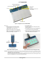
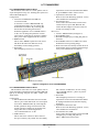
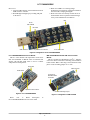
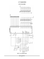
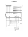
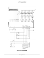
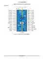
LC717A00ARGEVK Capacitance‐Digital‐Converter IC for Electrostatic Capacitive Touch Sensors Evaluation Board User's Manual http://onsemi.com EVAL BOARD USER’S MANUAL Introduction Capacitance Touch Sensor Evaluation Board This manual contains configuration, usage, setup guide (page 12), and main specifications regarding Capacitance touch sensor Evaluation board set (LC717A00ARGEVK). For the latest edition of this manual, please refer to ON Semiconductor homepage. Product Outline This set includes four (4) different Evaluation boards that can evaluate Capacitance touch sensor operation in various switch patterns and Communication tools to make register setting changes on PC. “LC717A00AR01GEVB” Capacitance Touch Sensor Evaluation Board “LC717A00AR02GEVB” Capacitance Touch Sensor Evaluation Board “LC717A00AR03GEVB” Capacitance Touch Sensor Conversion Module “LC717A00ARGPGEVB” Multi-functional USB−I2C Conversion Module “MM−FT232H” USB Cable EVALUATION BOARDS LC717A00AR01GEVB Evaluation Board set on “AC ADAPTER” side, power is supplied from DC jack. 3. DC Jack: This is used to connect AC adopter (+5 V). (Note: Using wrong polarity will damage this jack) 4. RESET switch: This is used to RESET Capacitance touch sensor LSI. Use this switch when Error LED is lit or if any abnormality is found during operation. 5. Error LED: This will light up when error is occurring in Capacitance touch sensor LSI. When this LED is lit, press RESET switch to release the error. 6. Capacitance touch sensor LSI: Please do not touch this during operation – It may cause malfunction or breakdown. 7. Touch switch area: An area where Touch switch is located. Touch switch is Green at power ON. When the user touches the Green light, Touch sensor will react and change the color to Red. This Evaluation board has 42 switch pattern with an LED on the center. Acrylic board is mounted on the board with a space of approx. 1.5 mm. When the user touches the Green light, which is lit under this acrylic board, the color will change to Red. Configuration 1. Connector for Multifunctional USB−I2C Conversion module: This is used to connect Multifunctional USB−I2C conversion module “MM−FT232H”. By using this module, user can connect the Evaluation board and PC. By connecting this Evaluation board to PC and activating Touch sensor evaluation application “LC717A00AR Software” on PC, user can change the parameter of touch sensor LSI, or can monitor an operation condition. Also, power will be supplied from this connector. 2. Power source switching jumper: This is used to set a supplier of the power source. If this is set on “PC” side, power is supplied from Multifunctional USB conversion module. If this is Semiconductor Components Industries, LLC, 2013 January, 2013 − Rev. 1 1 Publication Order Number: EVBUM2149/D LC717A00ARGEVK Connector for Multifunctional USB Conversion Module Power Source Switching Jumper RESET Switch Error LED Capacitance Touch Sensor LSI (LC717A00AR) DC Jack Touch Switch Area Figure 1. Configuration of LC717A00AR01GEVB 2. Press RESET switch. 3. Red LED will light up by touching Green LED light (See Figure 3). 4. Press RESET switch in case of error LED light up or when Evaluation board is acting strange. 5. Please note: If the user directly touches the IC on the Evaluation board or patterns with their finger, it may cause malfunction or breakdown. How to Use 1. When receiving power from PC, set Power switching jumper to “PC” side and connect “MM−FT232H” to the connector for Multifunctional USB conversion module (See Figure 2). If receiving power from optional AC adapter, set the jumper to “AC ADAPTER” side and connect AD adapter to DC jack. MM−FT232H Pin 1: Connect this with VDD Pin Pin 7: Unconnected Evaluation Board LC717A00AR01GEVB Figure 2. MM−FT232H Connection Figure 3. Red Turns On by Touching Green Light CAUTION: When supplying power from Multifunctional conversion module while having Power switch jumper on “AC ADAPTER” side, Green LED will slightly light up. This is because the current flows via I2C signal line and Pull-up resistor. PLEASE DO NOT USE IN THIS CONDITION – It may cause equipment failure. Also, please DO NOT supply power from both AD adapter and Multifunctional USB conversion module while having Power switch jumper on “AC ADAPTER” side – This may also cause equipment failure. http://onsemi.com 2 LC717A00ARGEVK LC717A00AR02GEVB Evaluation Board Capacitance touch sensor LSI. When this LED is lit, press RESET switch to release an error. 4. Capacitance Touch sensor LSI: Please do not touch this during operation – It may cause malfunction or breakdown. 5. Touch Switch Area: An area where Touch switch is located. Touch switch is Green at power ON. When the user touches the Green light, touch sensor will react and the color changes to Red. How to Use 1. Connect “MM−FT232H” (See Figure 2). 2. Press RESET switch. 3. Red LED will light up by touching silk prints on the board. 4. Press RESET switch if error LED is lit or when Evaluation board is operating strange. 5. Please note: If the user directly touches the IC on the Evaluation board or patterns with their finger, it may cause malfunction or breakdown. This Evaluation board has 81 switch pattern with an acrylic board placed on top of it. Touching the acrylic board will turn Red LED light on. Configuration 1. Connector for Multifunctional USB−I2C conversion module: A connector to connect “MM−FT232H”. By connecting this module, user can connect this Evaluation board with PC. By connecting this board to PC and activating Touch sensor Evaluation application “LC717A00AR software” on PC, user can change the parameter of touch sensor LSI, or can monitor an operation condition. Also, power will be supplied from this connector. 2. RESET switch: This is used to RESET Capacitance touch sensor LSI. Press this when error LED is lit or any abnormality is found during operation. 3. Error LED: This will light up when error is occurring in LED Connector for MM−FT232H Error LED Touch Switch Area RESET Switch Capacitance Touch Sensor Figure 4. Configuration of LC717A00AR02GEVB LC717A00AR03GEVB Evaluation Board this connector as USB device. In case of using “LC717A00AR Software”, please use pins for “MM−FT232H”. 3. Error LED: This will light up when error is occurring in Capacitance touch sensor LSI. When this LED is lit, unplug Evaluation board from PC and plug back again. 4. Capacitance Touch sensor LSI: Please do not touch this during operation – It may cause malfunction or breakdown. 5. Touch Switch Area, LED: An area where Touch switch is located. Red LED will light up by touching silk print area (SW1 ~ SW8) of the Touch switch. This Evaluation board has 42 switch pattern with an acrylic board placed on back side of the board. Red LED will light up by touching silk print area (SW1 ~ SW8) of the Touch switch. Configuration 1. Pin for Multi-functional USB conversion module: This is a pin to solder Pin header of 2.54 mm pitch and connect “MM−FT232H”. By connecting this module, parameter change of Touch sensor LSI and the operation condition can be monitored by using Touch sensor evaluation application “LC717A00AR Software” on PC. 2. USB Connector: This is used for PC connection. This connector does power delivery only and PC does not identify http://onsemi.com 3 LC717A00ARGEVK 3. When error LED is on or having strange Evaluation board operation, unplug the Evaluation board from PC, and plug back again. 4. Please note: If the user directly touches the IC on the Evaluation board or patterns with their finger, it may cause malfunction or breakdown. How to Use 1. Connect USB connector of the Evaluation board to USB connector of the PC. 2. Red LED light will light up by touching silk print on the board. LED Pin for MM−FT232H Error LED USB Connector Capacitance Touch Sensor Touch Switch Area Figure 5. Configuration of LC717A00AR03GEVB MM−FT232H Multifunctional USB−I2C Conversion Module LC717A00ARGPGEVB Conversion Module This is a sensor module with Capacitance touch sensor LSI “LC717A00AR” on DIP IC form of board that has 28 pins with 600 mil width. This is used to evaluate self-produced switch patterns. This is a module for USB Interface and I2Ct Interface conversion. This is used when connecting each Evaluation board and PC. When connecting to the Evaluation board, please set I/O switching jumper on 5 V side. Power LED USB Connector Reset Switch Connector for Evaluation Board Connection Capacitance Touch Sensor I/O Power Switching Jumper Figure 6. LC717A00ARGPGEVB Figure 7. Configuration of MM−FT232H Please refer to Detail Description LC717A00ARGPGEVB section for more detail. of http://onsemi.com 4 LC717A00ARGEVK MAIN SPECIFICATIONS Main specifications of each device are as listed below: Table 1. MAIN SPECIFICATIONS OF LC717A00AR01GEVB Parameter Conditions Ramarks Board Size 155 115 (mm) Board Material Glass Epoxy (FR4) Copper Foil 35 mm, Thickness 1.6 mm, Double-sided Board Supply Voltage 5V Provided from either DC Jack or MM−FT232H Capacitance Touch Sensor LC717A00AR External RESET Circuit With Manual REWSET Switch Switch Pattern 4 2 Configuration Connector 6 Pins 1 Row, DC Jack Table 2. MAIN SPECIFICATIONS OF LC717A00AR02GEVB Parameter Conditions Ramarks Board Size 127 28.5 (mm) Board Material Glass Epoxy (FR4) Copper Foil 35 mm, Thickness 1.6 mm, Double-sided Board Supply Voltage 5V Provided from MM−FT232H Capacitance Touch Sensor LC717A00AR External RESET Circuit With Manual REWSET Switch Switch Pattern 8 1 Configuration Connector 6 Pins 1 Row Table 3. MAIN SPECIFICATIONS OF LC717A00AR03GEVB Parameter Conditions Ramarks Board Size 29 69 (mm) Board Material Glass Epoxy (FR4) Copper Foil 35 mm, Thickness 1.6 mm, Double-sided Board Supply Voltage 5V Provided from USB Connector Capacitance Touch Sensor LC717A00AR External RESET Circuit N/A Switch Pattern 4 2 Configuration Connector USB A Type Table 4. MAIN SPECIFICATIONS OF LC717A00ARGPGEVB Parameter Conditions Ramarks Board Size 17.78 35.56 (mm) Board Material Glass Composite (CEM3) Supply Voltage 2.6 to 5.5 V Capacitance Touch Sensor LC717A00AR External RESET Circuit With Manual REWSET Switch Switch Pattern 4 2 Configuration Connector Connector 600 mil Width 28 Pins DIP Type Copper Foil 35 mm, Thickness 1.6 mm, Double-sided Board http://onsemi.com 5 LC717A00ARGEVK Unpopulated CIRCUIT DIAGRAMS Figure 8. LC717A00AR01GEVB http://onsemi.com 6 Unpopulated LC717A00ARGEVK Figure 9. LC717A00AR02GEVB http://onsemi.com 7 LC717A00ARGEVK Figure 10. LC717A00AR03GEVB http://onsemi.com 8 LC717A00ARGEVK Figure 11. LC717A00ARGPGEVB http://onsemi.com 9 LC717A00ARGEVK DETAIL DESCRIPTION OF LC717A00ARGPGEVB Configuration Touch Sensor LSI (LC717A00AR) Power LED RESET Switch Figure 12. Configuration of LC717A00ARGPGEVB http://onsemi.com 10 LC717A00ARGEVK Table 5. SIGNAL PIN FUNCTIONS No Name I/O Functions 1 Pout7 Output Cin0 Evaluation Result Output 2 Pout6 Output Cin1 Evaluation Result Output 3 Pout5 Output Cin2 Evaluation Result Output 4 Pout4 Output Cin3 Evaluation Result Output 5 Pout3 Output Cin4 Evaluation Result Output 6 Pout2 Output Cin5 Evaluation Result Output 7 Pout1 Output Cin6 Evaluation Result Output 8 Pout0 Output Cin7 Evaluation Result Output 9 ERROR Output ERROR State Output 10 Cref Input 11 Cdrv Output Reference Capacity Input Pin Output for Capacitive Sensor Drive 12 INTOUT Output Interruption Output 13 GAIN Input 14 GND − GND (EARTH) Power Source Pin for Gain Initial Value Selection (JP1 Initialization : H Level = 14) 15 Vdd − 16 SCL/SCK Input 17 SDA/SI I/O Data I/O (I2C)/Data Input (SPI) (2.2 kW Pull-up) 18 SA/SO I/O Slave Address Selection (I2C)/Data Output (SPI) (JP2 Initialization : L Level) 19 CS Input Interface Selection/Chip Select Inverting Input (SPI) 20 RESET Input External RESET Signal Inverting Input (2.2 kW Pull-up, with Switch) 21 Cin0 I/O Capacitive Sensor Input 22 Cin1 I/O Capacitive Sensor Input 23 Cin2 I/O Capacitive Sensor Input 24 Cin3 I/O Capacitive Sensor Input 25 Cin4 I/O Capacitive Sensor Input 26 Cin5 I/O Capacitive Sensor Input 27 Cin6 I/O Capacitive Sensor Input 28 Cin7 I/O Capacitive Sensor Input Clock Input (I2C)/Clock Input (SPI) (2.2 kW Pull-up) *For evaluation result output of Pout0~7; Evaluation result (ON/OFF) after removing Capacitive sensor input’s chattering will come out. Capacitive sensor’s measurement will become readable by connecting I2C compatible bus or SPI. Table 6. JUMPER, PATTERN FOR ADDITIONAL PARTS Pattern Parameter JP1 Initial Gain Setting Set Contents JP2 Slave Address Selection (I2C) / Data Output (SPI) When Interface is Selected as I2C Compatible Bus by CS Pin; H Level (2-3 Short) = 0x16 (7 Bits) L Level (1-2 Short) = 0x17 (7 Bits) *: Initial Setting: L Level C3 Pattern for Cref Capacity Adjustment Implement Capacitor of any Capacity as Needed (Size: 1608) H Level (1-2 Short) = High-sensitivity (14) *: Initial Setting: H Level L Level (2-3 Short) = Low-sensitivity (7) PRECAUTION FOR USE 1. For approach in the use of IC and the design rule of the sensor pattern that will become the switch: Please refer to the User’s manual and FAQ pages in ON Semiconductor homepage. 2. Regarding ON/OFF output change in accordance with long press of the switch: This happens with “Auto OFF function”. As a fail-safe function, if LSI is initial setting, output will be OFF after holding the switch for 10 seconds. By using Switch ON Count Lower/Higher Register in I2Ct compatible bus or SPI connection, the time to set OFF will be adjustable. http://onsemi.com 11 LC717A00ARGEVK SETUP GUIDE Connecting Multifunctional USB Conversion Module Thank you for purchasing our “LC717A00ARGEVK”, the Capacitance touch sensor Evaluation board. Where appropriate, please connect Capacitance touch sensor Evaluation board and Multifunctional USB conversion module as shown in the Figure 2. When connecting Multifunctional USB conversion module, make sure to have USB cable unplugged. When unplugging Multifunctional USB conversion module, please unplug USB cable before the module. Necessary Operational Environment Following operational environment is necessary in order to use “LC717A00AR Software”, the Touch sensor Evaluation board application. Correspondence OS: Windows XP (32 bit), Windows 7 (32 bit) Memory capacity: More than 16 MB Hard disc capacity: Amount of space ³ more than 500 kB (Application size). Need additional size (optional) for obtaining Log file. Interface: USB2.0 Use of AC Adapter Please use 5 V AC adapter when LC717A00AR01GEVB without connecting to PC. using NOTE: Please take extra care for polarity – Using wrong polarity may cause IC damage. Some AC adapter with large anti-ground noise may not be used. Setup 1. Download the “D2XX drivers” from the corporate home page of FTDI (http://www.ftdichip.com). 2. Decompress the zipped file. 3. Connect the “MM−FT232H” and the PC with USB Cable. 4. Install of “D2XX drivers” for “MM−FT232H”. Once the installation is done, disconnect “MM−FT232H” from PC. 5. Connect the “MM−FT232H” and the Touch sensor Evaluation board (LC717A00AR01GEVB or LC717A00AR02GEVB). Next, connect the “MM−FT232H” and the PC with USB Cable. 6. Download the LC717A00AR Software, from http://www.sanyosemi.com/en/touch-sensor/pdf/ LC717A00_Software.zip, and store on your PC. 7. Decompress the zipped file into the any directory. 8. Run the LC717A00AR Software “LC717A00ARApp.exe” in the above directory. 9. Please refer to the documents and tools at http://www.sanyosemi.com/en/touch-sensor/ index.php. Usage Advisory When using AC adapter, please switch the jumper of LC717A00AR01GEVB to AC adapter side. If error is displayed when starting “LC717A00AR Software”, please check the following: Please make sure that Device driver is operating correctly: If “!” is shown at “USB Serial Port” in Windows’ “Device manager”, Device driver is not operating correctly. In such a case, disconnect the device from PC and reconnect it again. If “!” still shows up on the screen after disconnecting so many times, please reinstall the Device driver. Additional documents, FAQ, and any updates regarding this set are posted on ON Semiconductor homepage. We recommend all users to check the homepage regularly. ON Semiconductor Touch sensor webpage: http://www.sanyosemi.com/en/touch-sensor/index.php Windows is a registered trademark of Microsoft Corporation I2C Bus is a trademark of Philips Corporation ON Semiconductor and are registered trademarks of Semiconductor Components Industries, LLC (SCILLC). SCILLC owns the rights to a number of patents, trademarks, copyrights, trade secrets, and other intellectual property. A listing of SCILLC’s product/patent coverage may be accessed at www.onsemi.com/site/pdf/Patent−Marking.pdf. SCILLC reserves the right to make changes without further notice to any products herein. SCILLC makes no warranty, representation or guarantee regarding the suitability of its products for any particular purpose, nor does SCILLC assume any liability arising out of the application or use of any product or circuit, and specifically disclaims any and all liability, including without limitation special, consequential or incidental damages. “Typical” parameters which may be provided in SCILLC data sheets and/or specifications can and do vary in different applications and actual performance may vary over time. All operating parameters, including “Typicals” must be validated for each customer application by customer’s technical experts. SCILLC does not convey any license under its patent rights nor the rights of others. SCILLC products are not designed, intended, or authorized for use as components in systems intended for surgical implant into the body, or other applications intended to support or sustain life, or for any other application in which the failure of the SCILLC product could create a situation where personal injury or death may occur. Should Buyer purchase or use SCILLC products for any such unintended or unauthorized application, Buyer shall indemnify and hold SCILLC and its officers, employees, subsidiaries, affiliates, and distributors harmless against all claims, costs, damages, and expenses, and reasonable attorney fees arising out of, directly or indirectly, any claim of personal injury or death associated with such unintended or unauthorized use, even if such claim alleges that SCILLC was negligent regarding the design or manufacture of the part. SCILLC is an Equal Opportunity/Affirmative Action Employer. This literature is subject to all applicable copyright laws and is not for resale in any manner. PUBLICATION ORDERING INFORMATION LITERATURE FULFILLMENT: Literature Distribution Center for ON Semiconductor P.O. Box 5163, Denver, Colorado 80217 USA Phone: 303−675−2175 or 800−344−3860 Toll Free USA/Canada Fax: 303−675−2176 or 800−344−3867 Toll Free USA/Canada Email: [email protected] N. American Technical Support: 800−282−9855 Toll Free USA/Canada Europe, Middle East and Africa Technical Support: Phone: 421 33 790 2910 Japan Customer Focus Center Phone: 81−3−5817−1050 http://onsemi.com 12 ON Semiconductor Website: www.onsemi.com Order Literature: http://www.onsemi.com/orderlit For additional information, please contact your local Sales Representative EVBUM2149/D