1
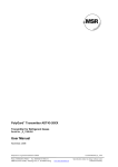
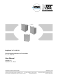
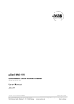
PolyGard® ADT53-1120 and ADT63-1125
Electrochemical Ammonia Transmitter
Serial No. AT03-003
User Manual
April 2008
PolyGard® is a registered trademark of MSR
Phone: 0049(0)8531/9004-0
Fax: 0049(0)8531/9004-54
MSR-Electronic-GmbH, Würdinger Str. 27, D 94060 Pocking
GAADTX31125_E-0408
www:msr-electronic.de
Specification subject to change without notice
Made in Germany
User Manual - PolyGard® NH3
ADT 53-1120 und ADT-63-1125
Page
2
1
Intended for Use....................................................................................................3
2
Functional Description .........................................................................................3
2.1
2.2
3
Mounting ................................................................................................................4
3.1
3.2
4
Calibration............................................................................................................................... 5
Manual Calibration.................................................................................................................. 6
Zero-point ............................................................................................................................ 6
Gain..................................................................................................................................... 6
Calculation of Control Voltage ............................................................................................ 6
Calibration with DGC-05 Service Tool.................................................................................... 7
Calibration with DGC-05 Configuration and Calibration Software.......................................... 7
Addressing, only for DGC-05_Bus Mode ............................................................................... 8
Option Relay Output ............................................................................................................... 8
Service and Inspection .........................................................................................9
6.1
6.2
6.3
7
Wiring Connection .................................................................................................................. 4
Commissioning .....................................................................................................5
5.1
5.2
5.2.1
5.2.2
5.2.3
5.3
5.4
5.5
5.6
6
Mounting Instructions.............................................................................................................. 4
Installation............................................................................................................................... 4
Electrical Connection ...........................................................................................4
4.1
5
Control Mode .......................................................................................................................... 3
Sensor..................................................................................................................................... 3
Inspections.............................................................................................................................. 9
Calibration............................................................................................................................... 9
Exchange of Sensor Element ................................................................................................. 9
Troubleshooting....................................................................................................9
7.1
7.2
Analog Mode........................................................................................................................... 9
DGC-05_Bus Mode .............................................................................................................. 10
8
Cross Sensivity Data ..........................................................................................10
9
Technical Data.....................................................................................................11
10
Figures .................................................................................................................13
11
Notes and General Information..........................................................................15
11.1
11.2
11.3
11.4
Intended Product Application................................................................................................ 15
Installers’ Responsibilities .................................................................................................... 15
Maintenance ......................................................................................................................... 15
Limited Warranty................................................................................................................... 15
PolyGard® is a registered trademark of MSR
Phone: 0049(0)8531/9004-0
Fax: 0049(0)8531/9004-54
MSR-Electronic-GmbH, Würdinger Str. 27, D 94060 Pocking
GAADTX31125_E-0408
www:msr-electronic.de
Specification subject to change without notice
Made in Germany
User Manual - PolyGard® NH3
ADT 53-1120 und ADT-63-1125
Page
3
Electrochemical Ammonia Transmitter
1 Intended for Use
The PolyGard® NH3 analog transmitter with digital processing of the measured values and temperature
compensation is used to detect leakages of ammonia in the ambient air.
The sites intended for use are all areas being directly connected to the public low voltage supply, e.g. domestic,
commercial and industrial ranges as well as small enterprises (acc. to EN 50 082).
The PolyGard® NH3 analog transmitter is not suitable for the application in areas exposed to explosive hazards.
2 Functional Description
2.1 Control Mode
In addition to the analog output the transmitter is equipped with a serial interface RS-485 for the connection to
the PolyGard® DGC-05 system.
Analog mode:
The analog output can be selected as current signal with (0)4-20 mA or as voltage signal (0)2-10 V. In the 4-20
mA mode and without any supplementary options, the ADTX3 also works in the 2-wire technique.
DGC-05_Bus mode:
The transmitter can be connected to the PolyGard® DGC-05 system via the RS-485 interface. In this mode
there is an analog input for the connection of an additional 4-20 mA transmitter. The two measuring values are
transmitted via the RS-485 interface to the gas controller.
The cable topology for the RS-485 bus can be taken from the “Guidelines for wiring and commissioning of the
DGC-05 hardware”.
The two control modes are available in parallel.
2.2
Sensor
The sensor portion of the transmitter is a sealed micro-fuel cell with three electrodes, sensing, counter and
reference. The ambient air enters the cell through a diffusion barrier into the liquid electrolyte of the sensor. The
chemical process of the measurement is one of reduction where one molecule of the target gas is exchanged
for one molecule of oxygen. The reaction drives the oxygen molecule to the counter electrode, generating a DC
microampere signal between the sensing and counter electrodes. This signal is linear to the volume
concentration of the sensed gas. The signal is evaluated by the connected amplifier and transformed into a
linear output signal.
Electrochemical processes always lead by-and-by to a loss of sensitivity. Therefore regular calibration of the
zero-point and of the gain is necessary. See also section 6.
Caution:
Avoid any force (e.g. by thumb) on the sensor element during operation or installation. This could destroy the
sensor element.
There is a small quantity of corrosive liquid in the sensor element. If in case of damage persons or objects
encounter the liquid, you have to clean the affected areas as fast and carefully as possible with tap water. Out
of use sensors must be disposed in the same way as batteries.
PolyGard® is a registered trademark of MSR
Phone: 0049(0)8531/9004-0
Fax: 0049(0)8531/9004-54
MSR-Electronic-GmbH, Würdinger Str. 27, D 94060 Pocking
GAADTX31125_E-0408
www:msr-electronic.de
Specification subject to change without notice
Made in Germany
User Manual - PolyGard® NH3
ADT 53-1120 und ADT-63-1125
Page
4
3 Mounting
Caution: Electronics can be destroyed by static electricity. Therefore, do not touch the equipment without a
wrist strap connected to ground or without standing on conductive floor. (acc. to DIN EN 100015).
3.1 Mounting Instructions
When choosing the mounting site please pay attention to the following:
•
The specific weight of Ammonia, NH3, is lower than that of air (factor 0,59).
•
Installation at the highest point possible with a distance of ca. 300 mm to the ceiling.
•
Select the location of the sensor according to local regulations.
•
Consider the ventilation conditions! Do not mount the transmitter in the center of the airflow (air
passages, suction holes)
•
Mount the transmitter at a location with minimum vibration and minimum variation in temperature
(avoid direct sunlight).
•
Avoid locations where water, oil etc. may influence proper operation and where mechanical damage
might be possible.
•
Provide adequate space for maintenance and calibration work.
Duct mounting
•
Mount only in a straight section of duct with minimum air vortex. Keep a minimum distance of 1 m (3,5
feet) from any curve or obstacle.
•
Mount only in a duct system with a maximum air velocity of 10 m/s (2000 ft/min) or less.
•
Mounting must be performed so that the airflow is in line with probe openings.
3.2 Installation
•
Open cover of enclosure. Unplug PCB from terminal blocks.
•
Fix bottom part by screws vertically to the wall (terminal blocks to the ground).
•
Re-plug the PCB at X4 and X5. Replace the cover.
4 Electrical Connection
Consider static electricity! See 3. Mounting.
•
Installation of the electrical wiring should only be performed by a trained specialist according to the
connection diagram and according to the corresponding regulations, without any power applied to
conductors!
•
Avoid any influence of external interference by using shielded cables.
•
Recommended cable for analog mode: J-Y(St)Y 2x2x0,8 LG (20 AWG), max. resistance 73 Ω/km
(20.8 Ω/1000 ft).
•
Required cable for RS-485 mode: J-Y(St)Y 2x2x0,8 LG (20 AWG), max. res. 73 Ω/km (20.8 Ω/1000 ft)
•
When the PBC is mounted, it is important to ensure that the wire shields or any bare wires do not short
the PCB.
4.1 Wiring Connection
•
Open cover of enclosure. Unplug PCB from terminal blocks X4 and X5.
•
Enter cable through hole; connect cable leads to the terminal blocks. See fig. 1 and 2.
•
Re-plug the basic PCB at the terminal blocks X4, X5. Close cover.
PolyGard® is a registered trademark of MSR
Phone: 0049(0)8531/9004-0
Fax: 0049(0)8531/9004-54
MSR-Electronic-GmbH, Würdinger Str. 27, D 94060 Pocking
GAADTX31125_E-0408
www:msr-electronic.de
Specification subject to change without notice
Made in Germany
User Manual - PolyGard® NH3
ADT 53-1120 und ADT-63-1125
Page
5
5 Commissioning
Consider commissioning instructions at any exchange of sensor elements.
Only trained technicians should perform the following:
•
Check mounting location.
•
Select output signal form: Current or voltage, and starting point 0 or 20%. See fig. 4.
•
Check supply voltage.
•
Check PCB AT03-003 for correct mounting at X4 and X5.
•
Check sensor element for correct mounting at terminal X3 of the PCB AT03-003.
•
Addressing of the transmitter in the DGC-05_Bus mode.
•
Calibration of the transmitter (if not factory-calibrated)
Required instruments to calibrate the transmitter:
•
Test gas bottle with synthetic air
•
Test gas bottle with test gas NH3 in the range of 20 to 70 % of the measurement range
•
Gas pressure regulator with flow meter to control the gas flow to 300 ml/min
•
Sensor head calibration adapter with tube. Type calibration set AT1110CO1. See Fig. 5.
•
Digital voltmeter with range 0 – 2 VDC, accuracy 1%.
•
Screwdriver small.
•
Calibration tool DGC-05 STL (only for calibration with service tool DGC-05).
•
DGC-05 configuration and calibration software incl. USB/RS-485 communication set (only for software
calibration mode).
Note:
Prior to calibration the sensor element must be fully stabilized by applying power voltage for at least 18 hours
without interruption.
Please observe proper handling procedures for test gas bottles according to TRGS 220!
NH3 calibration gas is toxic, never inhale the gas!
Symptoms at high concentrations: Loss of motility and consciousness.
Procedure if exposed: Get the victim into fresh air at once, consult doctor.
5.1 Calibration
Depending on the version and the control mode there are three different possibilities to calibrate the
transmitter:
Manual calibration
Manual calibration is only possible if the transmitter is equipped with the push-button “Zero” and the
potentiometer “Gain” (= version for manual calibration).
Manual calibration is possible both in analog mode and in DGC-05_Bus mode.
In the DGC-05_Bus mode the jumper V-A has to be set before manual calibration. Only by doing so the control
voltage is available at the test pins X6. Remove the jumper after calibration
Calibration with the Service Tool DGC-05
In the standard version (equipped with the communication connector X12) the transmitter is delivered for tool
and/or software calibration.
In the analog mode the service tool calibration is only possible with the 3-wire technique of the transmitter!
In the DGC-05_Bus mode calibration is always possible.
PolyGard® is a registered trademark of MSR
Phone: 0049(0)8531/9004-0
Fax: 0049(0)8531/9004-54
MSR-Electronic-GmbH, Würdinger Str. 27, D 94060 Pocking
GAADTX31125_E-0408
www:msr-electronic.de
Specification subject to change without notice
Made in Germany
User Manual - PolyGard® NH3
ADT 53-1120 und ADT-63-1125
Page
6
Software calibration via PC
In the standard version (equipped with the communication connector X12) calibration can also be done by
means of the configuration and calibration software.
Software calibration is possible for both control modes.
5.2 Manual Calibration
5.2.1 Zero-point
•
Connect the calibration adapter carefully to the sensor element.
•
Apply zero calibration gas, (0,3 l/min; 1 Bar ± 10%), or other clean air source to the sensor element.
•
Wait 3 minutes until the signal is about 40 mV and stable, then press the button Zero for 5 seconds.
Finished!
After successful calibration the measuring signal is corrected automatically. Depending on the
selected signal starting point the measuring signal shows the following values:
Signal start at 2 V or 4 mA
40 mV = 0 ppm
Signal start at 0 V or 0 mA
0 mV = 0 ppm
If the zero-point is out of the admissible range (> 20 mV at starting point 0% / > 60 mV at starting
point 20%) before calibration, there is no correction of the measuring signal. The sensor has to be
replaced.
•
Remove calibration adapter carefully by turning lightly. Inspect close seat of sensor element!
5.2.2 Gain
•
Connect calibration adapter carefully to the sensor element.
•
Apply test gas NH3 (20 to 70 % of the measurement range) to the sensor (0,3 l/min; 1 Bar ± 10%)
•
Wait 3 minutes until the sensor is stable, adjust signal with gain potentiometer ”Gain” until the signal
corresponds to the appropriate mVDC ± 3 mV (see calculation control voltage 5.3) and is stable.
•
Remove calibration adapter with a careful light turn. Inspect the correct mounting of the sensor
element.
By limiting the gain factor, calibration will not be possible any more when the sensitivity of the sensor
reaches a residual sensitivity of 30 %. Then the sensor has to be replaced.
5.2.3 Calculation of Control Voltage
Control voltage (mV) = 160 (mV) x test gas concentration NH3 (ppm)
measuring range NH3 (ppm)
+ 40 (mV)
Example
Measuring range NH3
300 ppm
1000 ppm
Test gas concentration NH3
205 ppm
405 ppm
Control voltage
149 mV
105 mV
160 (mV) x 205 (ppm) + 40 (mV) = 149 mV.
300 ppm
PolyGard® is a registered trademark of MSR
Phone: 0049(0)8531/9004-0
Fax: 0049(0)8531/9004-54
MSR-Electronic-GmbH, Würdinger Str. 27, D 94060 Pocking
GAADTX31125_E-0408
www:msr-electronic.de
Specification subject to change without notice
Made in Germany
User Manual - PolyGard® NH3
ADT 53-1120 und ADT-63-1125
5.3
Page
7
Calibration with DGC-05 Service Tool
•
Connect the DGC-05 Service Tool to the transmitter, open menu “Calibration”.
•
Enter measuring range and test gas concentration.
•
Connect calibration adapter carefully to the sensor element
•
Apply synthetic air (150 ml/min; 1 Bar (14.5 psi ) ± 10%), or NH3-free ambient air.
•
Wait until the measuring value is stable, and then perform automatic zero calibration.
•
Apply calibration test gas NH3 (20 to 70 % of the measurement range) to the sensor (0,3 l/min; 1 Bar ±
10%).
•
Wait until the measuring value is stable, and then perform automatic gain calibration.
•
Remove calibration adapter carefully by turning lightly. Check the sensor for correct mounting!
By limiting the gain factor, calibration will not be possible any more when the sensitivity of the sensor
reaches a residual sensitivity of 30 %. In this case the sensor has to be replaced.
Further information can be taken from the user manual of the DGC-05 Service Tool.
5.4
Calibration with DGC-05 Configuration and Calibration Software
•
Connect the PC via USB/RS-485 communication set to the transmitter, open menu “Calibration”.
•
Enter measuring range and test gas concentration.
•
Connect calibration adapter carefully to the sensor element
•
Apply synthetic air (150 ml/min; 1 Bar (14.5 psi ) ± 10%), or NH3-free ambient air.
•
Wait until the measuring value is stable, and then perform automatic zero calibration.
•
Apply calibration test gas NH3 (20 to 70 % of the measurement range) to the sensor (0,3 l/min; 1 Bar ±
10%).
•
Wait until the measuring value is stable, and then perform automatic gain calibration.
•
Remove calibration adapter carefully by turning lightly. Check the sensor for correct mounting!
By limiting the gain factor, calibration will not be possible any more when the sensitivity of the sensor
reaches a residual sensitivity of 30 %. In this case the sensor has to be replaced.
Further information can be taken from the user manual of the DGC-05 Configuration and Calibration Software.
PolyGard® is a registered trademark of MSR
Phone: 0049(0)8531/9004-0
Fax: 0049(0)8531/9004-54
MSR-Electronic-GmbH, Würdinger Str. 27, D 94060 Pocking
GAADTX31125_E-0408
www:msr-electronic.de
Specification subject to change without notice
Made in Germany
User Manual - PolyGard® NH3
ADT 53-1120 und ADT-63-1125
Page
8
5.5 Addressing, only for DGC-05_Bus Mode
In the DGC-05_Bus mode each transmitter gets its communication address.
In the standard version with the communication connector X12, addressing is done by means of the DGC-05
Service Tool or by the DGC-05 Configuration and Calibration Software. See user manual of the Service Tool or
of the Configuration and Calibration Software.
In the manual addressing version which can be identified by the address switch being equipped, there is a
maximum of 60 addresses to be selected. See fig. 3.
The jumper is responsible to define the address group and the switch to define the address according to the
following table.
Switch
position
0
1
2
3
4
5
6
7
8
9
A
B
C
D
E
F
Jumper pos. 01
= address
inactive
01
02
03
04
05
06
07
08
09
10
11
12
13
14
15
Jumper pos. 02
= address
inactive
16
17
18
19
20
21
22
23
24
25
26
27
28
29
30
Jumper pos. 03
= address
inactive
31
32
33
34
35
36
37
38
39
40
41
42
43
44
45
Jumper pos. 04
= address
inactive
46
47
48
49
50
51
52
53
54
55
56
57
58
59
60
5.6 Option Relay Output
The two relays are activated in dependence of the gas concentration. If the gas concentration exceeds the
adjusted alarm threshold, the corresponding relay switches on. If the gas concentration falls below the
threshold minus hysteresis, the relay switches off again.
The contact function for relay 2, NC (normally closed) or NO (normally open), can be selected via the jumper
NO/NC. See fig 1 and 3. Relay 1 is equipped with a change-over contact.
Via the ModBus interface the two alarm thresholds and the hysteresis are freely adjustable at the PC within the
measuring range. The procedure can be read from the user manual “ModBus Software”.
The following parameters are factory-set.
Alarm threshold 1 = Relay 1: 80 ppm
Alarm threshold 2 = Relay 2: 250 ppm
Switching hysteresis:
15 ppm
PolyGard® is a registered trademark of MSR
Phone: 0049(0)8531/9004-0
Fax: 0049(0)8531/9004-54
MSR-Electronic-GmbH, Würdinger Str. 27, D 94060 Pocking
GAADTX31125_E-0408
www:msr-electronic.de
Specification subject to change without notice
Made in Germany
User Manual - PolyGard® NH3
ADT 53-1120 und ADT-63-1125
Page
9
6 Service and Inspection
6.1 Inspections
Inspection, service and calibration of the transmitters have to be done by trained technicians and executed at
regular intervals. We therefore recommend to conclude a service contract with MSR or one of their authorized
partners.
6.2 Calibration
(See section 5.1 and 5.2)
•
At commissioning and at periodic intervals determined by the person responsible for the gas detection
system (recommendation: every 6 months)
•
After exchange of the sensor
•
If in case of operational or climatic influences the sensitivity of the sensor falls below 30 % in
operation, calibration will not be possible any more. Then the sensor has to be replaced.
6.3 Exchange of Sensor Element
Consider static electricity! See point 3.
Sensor should always be installed without voltage applied.
•
Unplug basic PCB AT03 carefully from the terminal blocks on base.
•
Unplug old sensor element from the PCB.
•
Take new sensor element out of original packing.
•
Plug in sensor element into the PCB AT03 at X3.
•
Plug in carefully the PCB AT03 into terminal block X4, X5.
•
Calibrate according to section 5.
7 Troubleshooting
7.1 Analog Mode
Trouble
Cause
Solution
Output signal < 3 mA / 1,5 V
and/or control voltage < 30 mV
only for starting signal 2V/4 mA
Jumper 0-20 % not set
Check jumper position
Power voltage not applied
Measure tension at X4:
Two-wire: Pin 1 (+) and 4 (-)
Three-wire: Pin 1 (+) and 2 (-)
PCB AT03 not plugged in correctly at X4
and X5
Replug PCB correctly
Output signal > 22 mA /220 mV
Control voltage does not reach
the calculated value
Wire break
Short-circuit
Check the wiring
Check the wiring
Sensor element not calibrated
Calibrate sensor element
Sensor sensitivity < 30 %
No reaction of the output signal
in spite of gas concentration
Power voltage not applied
Signal (Pin 4) not wired correctly
Replace sensor element
Measure tension at X4
PolyGard® is a registered trademark of MSR
Phone: 0049(0)8531/9004-0
Fax: 0049(0)8531/9004-54
MSR-Electronic-GmbH, Würdinger Str. 27, D 94060 Pocking
Check the wiring
GAADTX31125_E-0408
www:msr-electronic.de
Specification subject to change without notice
Made in Germany
User Manual - PolyGard® NH3
ADT 53-1120 und ADT-63-1125
7.2
Page
10
DGC-05_Bus Mode
Trouble
Cause
Solution
Yellow LED not shining
Power voltage not applied
Measure tension at X4:
Pin 1 (+) and 2 (-)
PCB not plugged in correctly at X4/X5
Replug PCB correctly
Yellow LED not flashing
Wire break
No communication at the transmitter
Check wiring
Transmitter not addressed,
check
bus
wiring
incl.
topology and termination
Voltage < 16 V
No control voltage at calibration
Jumper V-A not set
Set the jumper. Remove it
after calibration!
8 Cross Sensitivity Data
The cross sensivity depends on the used transmitter type and can be read from the table Technical Data (see
9.). Other gases can have an influence on the sensivity, too. The table does not claim to be complete. The
indicated sensivity data are only standard values referring to new sensor elements.
PolyGard® is a registered trademark of MSR
Phone: 0049(0)8531/9004-0
Fax: 0049(0)8531/9004-54
MSR-Electronic-GmbH, Würdinger Str. 27, D 94060 Pocking
GAADTX31125_E-0408
www:msr-electronic.de
Specification subject to change without notice
Made in Germany
User Manual - PolyGard® NH3
ADT 53-1120 und ADT-63-1125
Page
11
9 Technical Data
General sensor performances
Gas type
Sensor element
Measuring range
Pressure range
Humidity
Storage temperature range
Storage time
Accuracy
Repeatability
Zero-point
Long-term output drift
Response time
Temperature range
Life expectancy
Cross sensitivity*
Carbon monoxide; CO
Hydrogen H2
Sulphur dioxide SO2
Hydrogen sulphide H2S
Nitrate monoxide NO
Nitrogen dioxide NO2
Chlorine Cl2
Carbon dioxide CO2
Accuracy
Repeatability
Zero-point
Long-term sensitivity output drift
Response time
Temperature range
Life expectancy
Cross sensitivity*
Carbon monoxide; CO
Hydrogen H2
Sulphur dioxide SO2
Hydrogen sulphide H2S
Phosphates
Nitrogen dioxide NO2
Chlorine Cl2
Hydrogen chloride HCl
Carbon dioxide CO2
Alcohols
Amines
Arsines
Ammonia (NH3)
Electrochemical, diffusion
0 - 300 ppm / 0 - 1000 ppm
Atmosphere ± 15 %
15 – 90 % RH non condensing
5 °C to 20 °C
Max. 3 months
Type AT-53-1120
4 ppm
< 3 % of reading
0 ppm ± 16 ppm
< 5% signal loss/6 months
t90 < 35 sec.
-10 °C to + 40 °C
> 2 years/normal operating environment
Concentration
Reaction
300 ppm
0 ppm
200 ppm
0 ppm
20 ppm
- 7 ppm
20 ppm
7 ppm
20 ppm
- 1 ppm
20 ppm
- 20 ppm
20 ppm
- 55 ppm
2 % vol
0 ppm
Type AT-63-1125
< 15 ppm
< 5 % of reading
0 ppm ± 15 ppm
< 10% signal loss/6 months
t90 < 120 sec.; t50 < 20 sec.
-40 °C to + 10 °C
> 18 months/normal operating environment
Concentration
Reaction
100 ppm
95 ppm
3000 ppm
3000 ppm
20 ppm
5 ppm
20 ppm
40 ppm
300 ppm
0 ppm
10 ppm
0 ppm
5 ppm
0 ppm
10 ppm
0 ppm
0,5 % vol
0 ppm
1000 ppm
yes
--yes
0,2 ppm
0 ppm
PolyGard® is a registered trademark of MSR
Phone: 0049(0)8531/9004-0
Fax: 0049(0)8531/9004-54
MSR-Electronic-GmbH, Würdinger Str. 27, D 94060 Pocking
GAADTX31125_E-0408
www:msr-electronic.de
Specification subject to change without notice
Made in Germany
User Manual - PolyGard® NH3
ADT 53-1120 und ADT-63-1125
Electrical
Power supply
Power consumption (without options)
Output signal
Analog output signal
Selectable: Current / tension
Starting point 0 / 20 %
Serial interface
Transceiver
Physical
Enclosure*
Enclosure colour*
Dimensions*
Weight*
Protection class*
Mounting*
Cable entry
Wire connection
Wire distance
Guidelines
Warranty
Page
12
18 - 28 VDC/AC, reverse polarity protected
22 mA, max. (0,6 VA)
(0) 4 – 20 mA, load ≤ 500 Ω,
(0) 2 - 10 V; load ≥ 50 k Ω
proportional, overload and short-circuit proof
RS 485 / 19200 Baud
Stainless steel V2A
Natural, brushed
(B x H x T) ca. 113 x 135 x 45 mm
Ca. 0,5 kg
IP 55
Wall mounted, pillar mounted
Standard 1 x M 20
Screw-type terminal min. 0,25, max. 2,5 mm2
Current signal ca. 500 m
Voltage signal ca. 200 m
EMC Directive 89/336/EEG
CE
1 year on material (without sensor)
Options
Relay output
Alarm relay 1
Alarm relay 2
Power consumption
Warning buzzer
Acoustic pressure
Frequency
Power consumption
LCD-Display
LCD
Power consumption
Heating
Temperature controlled
Ambient temperature
Power supply
Power consumption
Analog input
Only for RS-485 mode
30 VAC/DC 0,5 A, potential-free, SPDT
30 VAC/DC 0,5 A, potential-free SPNO/SPNC
30 mA, max. 0,8 VA)
85 dB (distance 300 mm)
3,5 kHz
30 mA, max. 0,8 VA)
Two lines, 16 characters each, illuminated
10 mA, max. 0,3 VA)
3 °C ±2°C
- 40 °C
18 - 28 VDC/AC
0,5 A; 12 VA
4 – 20 mA overload and short-circuit proof,
input resistance 200 Ω
PolyGard® is a registered trademark of MSR
Phone: 0049(0)8531/9004-0
Fax: 0049(0)8531/9004-54
MSR-Electronic-GmbH, Würdinger Str. 27, D 94060 Pocking
GAADTX31125_E-0408
www:msr-electronic.de
Specification subject to change without notice
Made in Germany
User Manual - PolyGard® NH3
ADT 53-1120 und ADT-63-1125
Page
13
10 Figures
Application: Analog mode
Fig. 1
4-20 mA
24 VDC
0 VDC
7 Bus_B
6 Bus_A
1
5 4-20 mA_Inp
2
4 Analog_Out
3
3 24 VDC_Out
4
2 0 VDC
5
1 24 VDC
X5
X4
Transmitter
ADTX3
Two-wire connection
- 4 - 20 mA output signal without
Controller
4-20 mA
24 VDC
0 VDC
Option
7 Bus_B
Relay
6 Bus_A
1
5 4-20 mA_Inp
R1
2
4 Analog_Out
3
3 24 VDC_Out
4
2 0 VDC
5
1 24 VDC
R2
X5
X4
Transmitter
ADTX3
NO NC
Controller
Three-wire connection
- VDC output signal
- 0 – 20 mA output signal
- Relay output
- LCD display
- Heating
options
Application: DGC-05_Bus mode
Fig. 2
Option
7 Bus_B
Relay
6 Bus_A
1
5 4-20 mA_Inp
R1
2
4 Analog_Out
3
3 24 VDC_Out
4
2 0 VDC
5
1 24 VDC
R2
X4
X5
Transmitter
ADTX3
NO NC
Analog
Transmitter
4-20 mA
0 VDC
24 VDC
24 VDC
0 VDC
Bus_A
Bus_B
NO NC
Option
7 Bus_B
Relay
6 Bus_A
1
5 4-20 mA_Inp
R1
2
4 Analog_Out
3
3 24 VDC_Out
4
2 0 VDC
5
1 24 VDC
R2
X4
X5
Transmitter
ADTX3
Connection field bus and tension
Connection analog transmitter
- Two- or three-wire connection,
depending on transmitter type
PolyGard® is a registered trademark of MSR
Phone: 0049(0)8531/9004-0
Fax: 0049(0)8531/9004-54
MSR-Electronic-GmbH, Würdinger Str. 27, D 94060 Pocking
GAADTX31125_E-0408
www:msr-electronic.de
Specification subject to change without notice
Made in Germany
User Manual - PolyGard® NH3
ADT 53-1120 und ADT-63-1125
Page
PCB AT03
Fig. 3
14
Terminal block
Option
Manual
Addressing
V-A
2
1
Sensor
XA3-1 XA3-2
X4
Anal. Output
= V DC
= mA
ATX3_003
= NO
= NC
1
2
3
4
5
1 2 3 4 5 6 7
X5
NO/NC
3
Function Relay R2
Test
Zero
NO NC
5
0-20%
X5
Option
Relay
R2 R1
Connector
Service Tool
6
X4
1 2 3 4 5
7
4
Anal. Output
Start Point
= 20 %
=0%
Option
Manual
Calibration
Gain
Position
4 3 2 1
Selection analog output signal
Fig. 4
Jumper 0- 20 %
Jumper V-A
Output signal
Not set
Not set
0 – 20 mA
Set
Not set
4 – 20 mA
Not set
Set
0 – 10 V
Set
Set
2 – 10 V
Calibration adapter
Fig. 5
Type: Calibr-set AT 1110CO1
PolyGard® is a registered trademark of MSR
Phone: 0049(0)8531/9004-0
Fax: 0049(0)8531/9004-54
MSR-Electronic-GmbH, Würdinger Str. 27, D 94060 Pocking
GAADTX31125_E-0408
www:msr-electronic.de
Specification subject to change without notice
Made in Germany
User Manual - PolyGard® NH3
ADT 53-1120 und ADT-63-1125
Page
15
11 Notes and General Information
It is important to read this user manual thoroughly and clearly in order to understand the information and
instructions. The PolyGard® transmitters must be used within product specification capabilities. The appropriate
operating and maintenance instructions and recommendations must be strictly followed.
Due to ongoing product development, MSR reserves the right to change specifications without notice. The
information contained herein is based upon data considered to be accurate. However, no guarantee is
expressed or implied regarding the accuracy of these data.
11.1 Intended Product Application
The PolyGard® NH3 transmitters are designed and manufactured for control applications and air quality
compliance in commercial buildings and manufacturing plants.
11.2 Installers’ Responsibilities
It is the installer’s responsibility to ensure that all PolyGard® transmitters are installed in compliance with all
national and local codes and OSHA requirements. Installation should be implemented only by technicians
familiar with proper installation techniques and with codes, standards and proper safety procedures for control
installations and the latest edition of the National Electrical Code (ANSI/NFPA70). It is also essential to follow
strictly all instructions as provided in the user manual.
11.3 Maintenance
It is recommended to check the PolyGard® transmitter regularly. Due to regular maintenance any deterioration
of performance may easily be corrected. Re-calibration and part replacement may be implemented in the field
by a qualified technician and with the appropriate tools. Alternatively, the easily removable plug-in transmitter
card with the sensor may be returned for service to MSR-Electronic-GmbH.
11.4 Limited Warranty
MSR-Electronic-GmbH warrants the PolyGard® transmitters for a period of one (1) year from the date of
shipment against defects in material or workmanship. Should any evidence of defects in material or
workmanship occur during the warranty period, MSR-Electronic-GmbH will repair or replace the product at their
own discretion, without charge.
This warranty does not apply to units that have been altered, had attempted repair, or been subject to abuse,
accidental or otherwise. The warranty also does not apply to units in which the sensor element has been
overexposed or gas poisoned. The above warranty is in lieu of all other express warranties, obligations or
liabilities.
This warranty applies only to the PolyGard® transmitters. MSR-Electronic-GmbH shall not be liable for any
incidental or consequential damages arising out of or related to the use of the PolyGard® transmitters.
PolyGard® is a registered trademark of MSR
Phone: 0049(0)8531/9004-0
Fax: 0049(0)8531/9004-54
MSR-Electronic-GmbH, Würdinger Str. 27, D 94060 Pocking
GAADTX31125_E-0408
www:msr-electronic.de
Specification subject to change without notice
Made in Germany