1
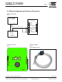
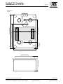
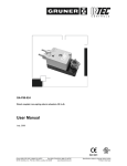
PolyGard CO LC-1112 V3 Electrochemical analog carbon monoxide transmitters serial no. EC-S 002 User Manual August 29, 2006 September 16, 2014 – Revision Polygard® is a registered trademark of MSR Customer Services (858) 578-7887 & (888) GO INTEC Fax (858) 578-4633 & (888) FX INTEC www.inteccontrols.com INTEC Controls, 12700 Stowe Dr., Suite 100, Poway, CA 92064 UMLC1112I01 Specification subject to change without notice. Printed in USA 140916 PolyGard® CO Transmitter User Manual - LC-1112 V3 Page 02 Electrochemical analog carbon monoxide transmitters 1 General Overview ...................................................................................................................... 3 2 Description .................................................................................................................................... 3 3 Installation ..................................................................................................................................... 4 3.1 3.2 4 Electrical Connection ............................................................................................................. 5 4.1 4.2 5 Calibration ................................................................................................................................. 6 Control span voltage calculation ............................................................................................... 7 Inspection and Service .......................................................................................................... 8 6.1 6.2 6.3 7 Instructions ................................................................................................................................ 5 Wiring connection ...................................................................................................................... 5 Start-up operation ..................................................................................................................... 6 5.1 5.2 6 Assembly information ................................................................................................................ 4 Enclosure................................................................................................................................... 4 Inspection .................................................................................................................................. 8 Calibration ................................................................................................................................. 8 Replacing of the sensor element............................................................................................... 8 Troubleshooting ........................................................................................................................ 8 7.1 Diagnostics of the transmitter.................................................................................................... 8 8 Cross-sensitivity Data ............................................................................................................ 9 9 Specifications ............................................................................................................................ 10 10 Wiring Configuration and Enclosure Dimensions ............................................ 11 11 Notes and General Information .................................................................................... 13 11.1 11.2 11.3 11.4 Intended product application ................................................................................................... Installers` responsibilities ........................................................................................................ Maintenance ............................................................................................................................ Limited warranty ...................................................................................................................... Polygard® is a registered trademark of MSR Customer Services (858) 578-7887 & (888) GO INTEC Fax (858) 578-4633 & (888) FX INTEC www.inteccontrols.com INTEC Controls, 12700 Stowe Dr., Suite 100, Poway, CA 92064 13 13 13 13 UMLC1112I01 Specification subject to change without notice. Printed in USA 140916 PolyGard® CO Transmitter User Manual - LC-1112 V3 Page 03 Electrochemical analog carbon monoxide transmitters 1 General Overview The PolyGardCO analog gas transmitter is used for detection of carbon monoxide in the ambient air to warn of the presence of Carbon Monoxide gas. 2 Description The sensor portion of the PolyGard LC-1112 analog gas transmitter is a micro-fuel cell, which is completely sealed. The measurement is a gas-in-liquid chemical reaction rather than a surface area measurement. With no surface area to coat, this sensor retains its sensitivity to carbon monoxide even after prolonged exposure to clean air. The cell consists of a diffusion barrier, O-ring seal, electrolyte reservoir and two electrodes. The target gas, carbon monoxide, enters the cell through a diffusion barrier. The chemical process of the measurement is one of oxidation where one molecule of the target gas is exchanged for one molecule of oxygen. The reaction drives the oxygen molecule to the counter electrode, generating a DC microampere signal between the sensing and counter electrodes. This signal is linear to the volume concentration of the sensed gas rather than the partial pressure. The integrated two-wire transformer converts this DC microampere signal to a standard 4-20 mA signal. Most sensors produce a small amount of baseline current in clean air. This is adjusted out with the zero potentiometer on the transmitter. This oxidation at the electrodes causes wear of the sensor. Typical life for this sensor is approximately five years in normal operation. This will vary somewhat from sensor to sensor, with some working lifetimes less than five years and some greater than 5 years. This wear also changes the characteristics of the sensor, requiring periodic re-calibration. It is recommended that the sensor accuracy be verified every six months and recalibrated as necessary. Polygard® is a registered trademark of MSR Customer Services (858) 578-7887 & (888) GO INTEC Fax (858) 578-4633 & (888) FX INTEC www.inteccontrols.com INTEC Controls, 12700 Stowe Dr., Suite 100, Poway, CA 92064 UMLC1112I01 Specification subject to change without notice. Printed in USA 140916 PolyGard® CO Transmitter User Manual - LC-1112 V3 Page 04 3 Installation Note: • • Avoid any force (e.g. by thumb) during operation or installation on the sensor element. This could destroy the element. Electronics can be destroyed through static electricity. Therefore, do not work on the equipment without a wrist strap connected to earth ground or standing on conductive floor. 3.1 Assembly information • • • • • • The specific weight of carbon monoxide is almost the same as that of air (factor 0.967). Location of the sensor must conform to the layout of the area being monitored. Disregard the ventilation ratio! Do not mount sensor in the center of the airflow. In larger rooms, it might be necessary to install two or more transmitters where there is not adequate air movement. Do not mount in corners or directly in front of air inlets (e.g. doors, windows, open ramps, dampers, etc.). In areas with undefined air movement, it might be necessary to distribute several transmitters in a vertical and horizontal direction over the whole area to be monitored. Avoid locations where water, oil etc. may influence proper operation and where mechanical damage might be possible. Mounting height is five feet above floor (max. 6 feet). Provide adequate space around sensor for maintenance and calibration work. 3.2 Enclosure − Un-screw cover of enclosure. − Carefully unplug the basic PCB mounted on fixed terminal blocks. − Screw the base vertically on wall or on a single gang electrical box. (see Fig. 3, page 12). − Plug in the basic PCB and replace the cover after wiring connection is completed (see 4.2 wiring connection). Polygard® is a registered trademark of MSR Customer Services (858) 578-7887 & (888) GO INTEC Fax (858) 578-4633 & (888) FX INTEC www.inteccontrols.com INTEC Controls, 12700 Stowe Dr., Suite 100, Poway, CA 92064 UMLC1112I01 Specification subject to change without notice. Printed in USA 140916 PolyGard® CO Transmitter User Manual - LC-1112 V3 Page 05 4 Electrical Connection 4.1 Instructions Note: Electrostatic discharge (ESD) may damage electronic components. During wiring, open the cover only when completely grounded via grounding strap or standing on conductive floor. • • • • • Connections should be made without any power applied to conductors. Installation of the electrical wiring should be according to the connection diagram and only performed by a trained specialist. Avoid any influence from external interference by using a shielded cable. Recommended cable: 18 AWG shielded, maximum resistance 20.8 Ω/1000 ft (73 Ω/1000 m) Cable insulation: Since the PCB mounts on top of the wiring terminations, it is important to ensure that the wire shields or any bare wires do not short to the PCB. Terminal strip X4 Connector 1 Connector 2 Connector 4 Power supply (+) 24 VDC, 17 – 28 VDC 0 VDC (DC common, not needed) Signal 4 – 20 mA 4.2 Wiring connection • • Unscrew cover of enclosure. Unplug basic PCB from terminal blocks. For single gang electrical box mounting: • Pull through cable via hole in base; connect cable leads on terminal block X4. For surface mounting (cable entry always from the top • Remove cover to access cable. • Connect cable leads on terminal block X4. • Plug the PCB on fixed terminal blocks on base. • Screw cover on base. Polygard® is a registered trademark of MSR Customer Services (858) 578-7887 & (888) GO INTEC Fax (858) 578-4633 & (888) FX INTEC www.inteccontrols.com INTEC Controls, 12700 Stowe Dr., Suite 100, Poway, CA 92064 UMLC1112I01 Specification subject to change without notice. Printed in USA 140916 PolyGard® CO Transmitter User Manual - LC-1112 V3 Page 06 5 Start-up operation Only trained technicians should perform the following: • • • • Check mounting location. Check power voltage. Check PCB for proper mounting at X4 and X5. Verify transmitter operation (sensor/transmitter was factory calibrated). Note: If calibration is necessary, the sensor element must be powered and be fully stabilized for at least 1 hour. Required instruments to calibrate the transmitter: • Test gas bottle with synthetic air. • Test gas bottle with 200 ppm CO. • Gas pressure regulator with flow meter to control the gas flow to 150 ml/min. • Calibration set CONKIT-E/CH-LC. See fig. 4. • Digital voltmeter with range 0 – 2 VDC, accuracy 1% and a small screwdriver. Note: Please observe proper handling procedures for test gas bottles! 5.1 Calibration Zero adjustment Zero-point calibration (4mA): (After sensor warm-up) • Connect digital voltmeter to test pins – and + (with a range selected that will display 2 VDC max.). • Connect the calibration adapter to sensor element. • Apply sensor element zero calibration gas, (150 ml/min; 14.5 psi ± 10%), or other clean air source. • Wait two minutes until the signal is stable, adjust signal with zero potentiometer ”Zero” until the signal is 40 mV ± 3 mV and stable. • Remove calibration adapter carefully by turning lightly. Polygard® is a registered trademark of MSR Customer Services (858) 578-7887 & (888) GO INTEC Fax (858) 578-4633 & (888) FX INTEC www.inteccontrols.com INTEC Controls, 12700 Stowe Dr., Suite 100, Poway, CA 92064 UMLC1112I01 Specification subject to change without notice. Printed in USA 140916 PolyGard® CO Transmitter User Manual - LC-1112 V3 Page 07 Span adjustment Notes: CO calibration gas is toxic, never inhale the gas! Symptoms: Dizziness, headache and nausea. Procedure if exposed: Bring into fresh air at once, consult doctor. • • • • Connect calibration adapter to the sensor element. Apply sensor element span calibration gas (200 ppm CO), (150 ml/min; 14.5 psi ± 10%). Wait two minutes until the signal is stable, adjust signal with span potentiometer ”Gain” until the signal reads the appropriate mVDC (± 3 mV, see calculation for control voltage 5.2) and is stable. Remove calibration adapter with a careful light turn. Inspect the seating of the sensor element! 5.2 Control span voltage calculation 160 (mV) x test gas concentration (ppm) Measuring range CO (ppm) + 40 (mV) Example Measuring range CO concentration Test gas concentration Control voltage 250 ppm 200 ppm 168 mV 160 (mV) x 200 (ppm) + 40 (mV) = 250 (ppm) 168 mV Polygard® is a registered trademark of MSR Customer Services (858) 578-7887 & (888) GO INTEC Fax (858) 578-4633 & (888) FX INTEC www.inteccontrols.com INTEC Controls, 12700 Stowe Dr., Suite 100, Poway, CA 92064 UMLC1112I01 Specification subject to change without notice. Printed in USA 140916 PolyGard® CO Transmitter User Manual - LC-1112 V3 Page 08 6 Inspection and Service 6.1 Inspection Inspection and service of the transmitters should be done by a trained technician and executed on a periodic interval. It is recommended that the sensor operation be verified at least every six months. 6.2 Calibration (See part 5.1 and 5.2) • Service at periodic intervals is to be decided by the person responsible for the gas detection system. • If span calibration voltage of 168 mV (see note below) is no longer attainable when applying 200 ppm Carbon Monoxide in air, then the sensor element has to be replaced. After the sensor element has been replaced a calibration is required. Note: If using a different level of span test gas ppm, or different sensor range, then the mV needs to be calculated. 6.3 Replacing of the sensor element Static electricity (see section 4.1). Sensor should always be installed without power applied: • • • • • • Unplug basic PCB carefully from the terminal blocks on the base. Unplug old sensor element out from the PCB. Take new sensor element out of original packing Plug sensor element in the PCB. Plug the PCB in terminal block X4, X5 carefully. Calibrate after sensor warm-up (see section 5.1). 7 Troubleshooting 7.1 Diagnostics of the transmitter Trouble Reason Solution Output signal 0 mA and control voltage 0 V Power not applied Basic PCB X4 and X5 not plugged in correctly Measure power voltage terminal block X4 terminal 1 (+) and 4 for 17 – 28 VDC Plug in the basic PCB into X4 and X5 correctly Output signal less then 4 mA Sensor element not calibrated Calibrate sensor element output Control current signal not correct Sensor span not attainable Replace sensor element Polygard® is a registered trademark of MSR Customer Services (858) 578-7887 & (888) GO INTEC Fax (858) 578-4633 & (888) FX INTEC www.inteccontrols.com INTEC Controls, 12700 Stowe Dr., Suite 100, Poway, CA 92064 UMLC1112I01 Specification subject to change without notice. Printed in USA 140916 PolyGard® CO Transmitter User Manual - LC-1112 V3 Page 09 8 Cross-sensitivity Data This table shows the typical response to be expected from the sensor when exposed to the following gases. Gas Acetone Chemical mark Gas concentration Tolerance ppm CO (CH3)CO(CH3) 1000 ppm 0 ppm Acetylene C2H2 40 ppm 80 ppm Ammonia NH3 100 ppm 0 ppm Carbone dioxide CO2 5000 ppm 0 ppm Chlorine CL2 2 ppm 0 ppm Ethanol C2H5OH 2000 ppm 5 ppm H2 100 ppm 20 ppm H2 S 25 ppm 0 ppm Iso propanol C2H7OH 200 ppm 0 ppm Nitric oxide NO 50 ppm 8 ppm Nitrogen dioxide NO2 50 ppm 1 ppm Sulphur dioxide SO2 50 ppm 0 ppm Hydrogen Hydrogen sulphide Polygard® is a registered trademark of MSR Customer Services (858) 578-7887 & (888) GO INTEC Fax (858) 578-4633 & (888) FX INTEC www.inteccontrols.com INTEC Controls, 12700 Stowe Dr., Suite 100, Poway, CA 92064 UMLC1112I01 Specification subject to change without notice. Printed in USA 140916 PolyGard® CO Transmitter User Manual - LC-1112 V3 Page 10 9 Specifications Electrical Power supply: Power consumption: RFI/EMI protection Sensor Performance Gas detected Sensor element Range Stability & resolution Repeatability Long term output drift Response time Sensor life expectancy Sensor coverage Mounting height Type of Control Analog output signal Operating Environment Working temperature Intermitted temperature Storage temperature Working humidity Intermitted humidity Pressure range Physical characteristics Enclosure material Enclosure color Protection Installation Dimensions (HxWxD) Cable entry Wire connection Wire size Wire distance Weight Approvals/Listings - Unit rating - Enclosure 17-28 VDC (polarity protected) 22 mA, (0.6 VA), max. 5.0 W @1 ft. (0.31 m) radiated Carbon monoxide (CO) Electrochemical, diffusion 0 – 250 ppm factory set 0 - 200 to 0 – 300 ppm, adjustable via calibration ± 3.0 ppm of reading ± 3.0 % of reading 0.4% signal loss/month t90 50 sec. 3-5 year, normal operating environment 5,000 sq.ft., (465 m2), to10,000 sq.ft. (930 m2) under “ideal conditions” 5 to 6 ft. (1.5 to 1.8 m) above floor Proportional, 4 – 20 mA, load 450 14 °F to 122 °F (-10 °C to + 50 °C) -4 °F to 122 °F (-20 °C to 50 °C) 41 °F to 86 °F (5 °C to + 30 °C) 15 to 95% RH non-condensing 0 to 99% RH non-condensing Atmospheric ±10% High impact, GW-Plast, IEC 60695-2-12, GWFI-650 °C, fire-retardant Light gray NEMA12 (IP 55) Wall (surface) mounted or single gang electrical box 5.0 x 3.4 x 2.2 in. (127 x 87 x 56 mm) 1 hole for ½ in. conduit for wall (surface) mounting, and 1 hole on back side of base plate for single gang electrical box mounting Terminal blocks, screw type for lead wire Min. 24 AWG (0.25 mm2), max. 14 AWG (2.5 mm2) Max. loop resist. 500 (= wire resist. + controller input resist.) 0.6 Ibs. ( 0.25 kg ) NRTL Performance Tested & Certified, Conforms to STD ANSI/UL 2075 City of Los Angeles CE VDI 2053, air treatment systems for garages and tunnels EMV-Compliance 89/336/EWG, low voltage directives 73/23/EWG UL Listed, E208470 CSA Certified, E208470 Polygard® is a registered trademark of MSR Customer Services (858) 578-7887 & (888) GO INTEC Fax (858) 578-4633 & (888) FX INTEC www.inteccontrols.com INTEC Controls, 12700 Stowe Dr., Suite 100, Poway, CA 92064 UMLC1112I01 Specification subject to change without notice. Printed in USA 140916 PolyGard® CO Transmitter User Manual - LC-1112 V3 Page 11 10 Wiring Configuration and Enclosure Dimensions Wiring Configuration Fig. 1 Power supply 17 - 28V/DC X4 7 BUS B 6 BUS A 5 4-20 mA_Inp 4 Output (V/mA) 3 24 VDC_Out 2 0 VDC 1 24 VDC_Inp + 4-20mA 0V/DC - Transmitter LC-1112 X5 1 2 3 4 5 Controller Calibration adapter Fig. 4 Type: CONKIT-E/CH-LC Gain Zero Sensor 4 3 2 1 P2 X6 + Test P1 7 Bus_B 6 Bus_A 5 INP 4 OUT 3 <24VDC 2 GND 1 >24VDC 1 2 3 4 5 6 7 Printed circuit board Fig. 2 X5 1 NO1 2 NC1 3 COM1 4 NO2 5 COM2 EC-S-002 240703 Polygard® is a registered trademark of MSR Customer Services (858) 578-7887 & (888) GO INTEC Fax (858) 578-4633 & (888) FX INTEC www.inteccontrols.com INTEC Controls, 12700 Stowe Dr., Suite 100, Poway, CA 92064 UMLC1112I01 Specification subject to change without notice. Printed in USA 140916 PolyGard® CO Transmitter User Manual - LC-1112 V3 Page 12 d = 0.16 in. (4 mm) Dimensions Fig. 3 d = 0.16 in. (4 mm) 3.3 in. (84 mm) 0.87 in. (22 mm) 1 2 3 4 5 6 7 3.19 in. (81 mm) 1 2 3 4 5 4.9 in. (125 mm) d = 0.88 in. (22,5 mm) 2.2 in. (55 mm) 3.35 in. (85 mm) Polygard® is a registered trademark of MSR Customer Services (858) 578-7887 & (888) GO INTEC Fax (858) 578-4633 & (888) FX INTEC www.inteccontrols.com INTEC Controls, 12700 Stowe Dr., Suite 100, Poway, CA 92064 UMLC1112I01 Specification subject to change without notice. Printed in USA 140916 PolyGard® CO Transmitter User Manual - LC-1112 V3 Page 13 11 Notes and General Information It is important to read this user manual thoroughly and clearly understand the information and instructions. The PolyGard® transmitters must be used within product specification capabilities. The appropriate operating and maintenance instructions and recommendations must be followed. Due to ongoing product development, MSR reserves the right to change specifications without notice. The information contained herein is based upon data considered to be accurate. However, no guarantee is expressed or implied regarding the accuracy of this data. 11.1 Intended product application The PolyGard® CO LC-1112 transmitters are designed and manufactured for control applications for energy savings and OSHA air quality compliance in commercial buildings and manufacturing plants (i.e.,detection and automatic exhaust fan control for automotive maintenance facilities, enclosed parking garages, engine repair shops, warehouses with forklifts, fire stations, tunnels, etc.). 11.2 Installers` responsibilities It is the installer`s responsibility to ensure that all PolyGard ® transmitters are installed in compliance with all national and local codes and OSHA requirements. Installation should be implemented only by individuals familiar with proper installation techniques and with codes, standards and proper safety procedures for control installations and the latest edition of the National Electrical Code (ANSI/NFPA70). It is also essential to strictly follow all instructions as provided in the user manual. 11.3 Maintenance It is recommended that the PolyGard® transmitter performance check is done on a routine schedule. Any performance deviations may be serviced based on needed requirements. Re-calibration and part replacement may be implemented in the field by a qualified individual and with the appropriate tools. Alternatively, the easily removable plug-in transmitter card with the sensor may be returned for service to INTEC Controls. 11.4 Limited warranty MSR-Electronic-GmbH and INTEC Controls warrants the PolyGard® transmitter for a period of two years, 12 months normal exposure for the sensor, from the date of shipment against defects in material or workmanship. Should any evidence of defects in material or workmanship occur during the warranty period, INTEC Controls will repair or replace the product at their own discretion, without charge. This warranty does not apply to units that have been altered, had attempted repair, or been subject to abuse, accidental or otherwise. The warranty also does not apply to units in which the sensor element has been overexposed or gas poisoned. The above warranty is in lieu of all other express warranties, obligations or liabilities. This warranty applies only to the PolyGard® transmitter. MSR-Electronic-GmbH and/or INTEC Controls shall not be liable for any incidental or consequential damages arising out of or related to the use of the PolyGard® transmitter. If the PolyGard® transmitter needs to be returned to INTEC Controls for service, an RMA number must be obtained prior to sending. Polygard® is a registered trademark of MSR Customer Services (858) 578-7887 & (888) GO INTEC Fax (858) 578-4633 & (888) FX INTEC www.inteccontrols.com INTEC Controls, 12700 Stowe Dr., Suite 100, Poway, CA 92064 UMLC1112I01 Specification subject to change without notice. Printed in USA 140916