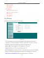
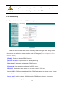
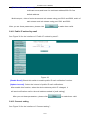
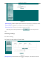
1
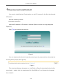
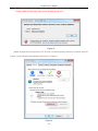
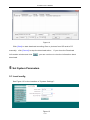
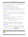
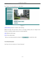
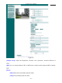
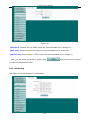
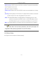
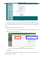
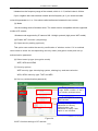
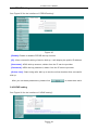
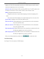
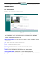
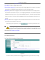
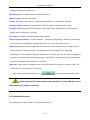
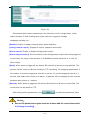
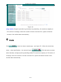
IP Camera IE Browser User Manual (for Windows XP/2003/Win7/Vista) Document edition:V1.1 The manual for: V1.6(8).0.119 and above editions Editions suit for IPC: Box IP camera, Infrared box IP camera, Dome IP c amera, Speed dome IP camera IP Camera IE Browser User’s Manual Preface Thank you for using our IP camera products. This series of products are all -in-one IP cameras designed for network video surveillance, including box IP camera, infrared box IP camera, dome IP camera, speed dome IP camera, etc. The products adopt high performance and powerful single SOC chip media processor to integrate audio and video capture, compression and transmission. Standard H.264 Baseline and Main Profile coding algorithm ensures clearer and smoother video transmission effect. Built-in Web Server allows users to easily perform real-time monitoring and remote control over front-end cameras via IE browser. This series of IP cameras is suitable for small and medium -sized enterprises, families, and other environments that require remote network video transmission and monitoring. It is easy to install and operate. 2/52 IP Camera IE Browser User’s Manual Statement: Contents in this manual may be different from the edition that you are using. Should any unsolved problem occur given that the product is used according to this manual, please contact our technical support department or your product suppliers. The content of this manual may be updated at irregular intervals without prior notice. Readership: This manual is suitable for engineers as follow: System planning person Support and maintenance person Administrator User Notes: “IP Camera” mentioned in this manual refers to network camera, including box camera, dome IP camera, infrared box IP camera, speed dome IP camera,etc. Click: Press the left mouse button once. Double-click: Press the left mouse button twice. “[ ]”:Window name, menu name and data sheet. 3/52 IP IP Camera IE Browser User’s Manual Modify record: Recording the corresponding update, the latest document include all of the content in previous editions. Modify date Edition Explanation 4/52 IP Camera IE Browser User’s Manual Table of Contents 1 Download and install ActiveX......................................................................................................................... 6 2 Login .................................................................................................................................................................. 8 3 Live Preview ..................................................................................................................................................... 9 4 Record Playback............................................................................................................................................ 10 5 Set System Parameters................................................................................................................................ 13 5.1 Local config ........................................................................................................................................... 13 5.2 Audio Setting ......................................................................................................................................... 14 5.3Video Settings ......................................................................................................................................... 15 5.3.1 Text Overlay ............................................................................................................................. 15 5.3.2 Video Coding ........................................................................................................................... 15 5.3.3 Video Mask .............................................................................................................................. 18 5.3.4 Video Parameter ..................................................................................................................... 18 5.3.5 Picture Parameter ................................................................................................................... 21 5.4 Network Settings ................................................................................................................................... 21 5.4.1 Basic Setting ............................................................................................................................ 21 5.4.2 LAN Setting .............................................................................................................................. 22 5.4.3 Wireless Setting ...................................................................................................................... 23 5.4.4 PPPOE Setting ........................................................................................................................ 27 5.4.5UPNP setting ............................................................................................................................ 27 5.4.6 Email setting ............................................................................................................................ 28 5.4.7 FTP setting ............................................................................................................................... 30 5.4.8 DDNS setting ........................................................................................................................... 31 5.4.9 VPN setting .............................................................................................................................. 32 5.4.10 RTSP setting.......................................................................................................................... 33 5.4.11 Public IP noticed by email .................................................................................................... 34 5.4.12 Connect setting ..................................................................................................................... 34 5.5 Storage Settings ..................................................................................................................................... 35 5.5.1 Device Setting ......................................................................................................................... 35 5.5.2 Record Setting ......................................................................................................................... 36 5.5.3 Snap Setting ............................................................................................................................ 37 5.6 Alarm Settings ....................................................................................................................................... 38 5.6.1 Motion detection ...................................................................................................................... 38 5.6.2 Sensor Detection..................................................................................................................... 39 5.6.3 Network Detection................................................................................................................... 40 5.7 COM Setting.......................................................................................................................................... 42 5.8 System Setting ....................................................................................................................................... 42 5.8.1 System Info .............................................................................................................................. 42 5.8.2 System Time ............................................................................................................................ 43 5.8.3 User Manage ........................................................................................................................... 44 5.8.4 Upgrade .................................................................................................................................... 45 5.8.5 PTZ Upgrade ........................................................................................................................... 46 5.8.6 Restore ..................................................................................................................................... 46 5.8.7 Reboot ...................................................................................................................................... 47 5.8.8 System log ............................................................................................................................... 47 Appendix 1 Network Interface of IP Camera ................................................................................................ 50 Appendix 2 Default Network Parameters ...................................................................................................... 50 Appendix 3 FAQs .............................................................................................................................................. 50 5/52 IP Camera User’s Manual 1 Download and install ActiveX You need to install ActiveX Control when you visit IP camera for the first time through IE browser. ActiveX installing method: Download installation Input the IP address of IP camera in Internet Explore to enter into login page(see Figure 1), Click [File] to download the ActiveX: Figure 1 You can download the ActiveX manually or just input the password,then download the file as system prompt.(see Figure 2) Figure 2 File download dialogue box pops up, click [Run] or [Save] to download ActiveX, after download it , double-click the downloaded file “WebCMS.exe” and choose the language, then install it. 6/52 IP Camera User’s Manual NOTE: Abnormal phenomenon when install ActiveX and the solutions: 1: when install the ActiveX,it pops up the window as Figure 3: Figure 3 please change the security level of IE, IE tools-> Internet options->Security->Custom level as Figure 4, and change the parameters as Figure 5, Figure 6: Figure 4 7/52 IP Camera User’s Manual Figure 5 Figure 6 2 Login Reopen Internet Explorer after ActiveX installation completes, input IP address of the IP camera to turn to login page, enter username and password (default setting is admin/admin), click login to enter into main interface(see Figure 7): 8/52 IP Camera User’s Manual Figure 7 3 Live Preview See Figure 8 for the interface of “Live Preview”: Figure 8 In the Live view interface, users can do operations like Snapping, Recording, 9/52 IP Camera User’s Manual Playback, Call, Listen, Clear Alarm, Log Search, Local Zoom of Image, Full-screen Viewing, PTZ and Lens Control. [Main Stream] Call the main stream of camera to get the best quality. [Sub Stream] Call the sub stream of camera, with low resolution,suit for bad network or Internet. [Snap]: click “Snap”, snap the current image and save it in .JPG format automatically to the storage directory of snapped images. [Record]: Manual image recording, automatically record current images and save them in .264 format to the storage directory of recorded images after the re cording function turned on. Displayed status after recording starts: [Call]: After turn on the audio talkback switch, the talkback between PC and IP camera can be performed given that audio talkback device is installed to the IP camera. The displayed status after audio turns on: [Listen]: After switch on the monitoring switch, PC can monitor the sound at the device end. The displayed status after monitoring starts : [Zoom]: This feature allows the manual drag and drop of video display area to realize partial zoom in. [Full]: Display images in full-screen, right click or click Esc to exit full screen mode. [Original]:Click “Original” to get the real W:H ratio of image, avoid image distortion when stretch to the size of screen. [PTZ ]: Allows four-directional rotation, automatic adjustment of PTZ rotation speed. [Image]:Click Image, allow users to adjust Brightness,Contrast,Hue and Saturation of image. 4 Replay Click enter into video playback page (see Figure 9). 10/52 IP Camera User’s Manual Figure 9 Users can search for recorded image files or snapped pictures in local PC or storage device according to date. [PC]: Users can select certain date to perform recorded image file or snapped picture (stored in local PC) searching. [SD Card]: Users can select certain date to perform recorded image file or snapped picture (stored in device SD card) searching. [File List]: Shows the recorded image files or snapped pictures searched in the File List. The way to search for recorded image files or snapped pictures of a specific period(see Figure 10): 11/52 IP Camera User’s Manual Select the storage media SD card or PC which keep the recording and images List all recording files or images Figure 10 [Play]: Choose the recorded image or snapped picture in file list, right click the file or picture or click “play” button to play. The contents will be displayed in the right window, users can view the playing information and control the process(see Figure 11): Figure 11 [Down]: Select the recorded files or snapped pictures searched from SD card in the file list, click “download” button to download the files to PC. [Info]: Users can view the information downloaded after clicking “Download”(see Figure 12): 12/52 IP Camera User’s Manual Figure 12 Click [Start] to start download recording files or pictures from SD card to PC manually,click [Cancel] to stop the download action,.If you close the Download Information window and click ,you can continue to view the information about download. 5 Set System Parameters 5.1 Local config See Figure 13 for the interface of “System Settings”: Figure 13 13/52 IP Camera User’s Manual [Preview mode]:users can choose Real time priority or Fluency priority mode according to their needs. [Reset Mosaic]:select this option to make image quality better, but CPU usage rate will be higher at the same time. [Record file packing time]:set packing time of record files for local PC when it is recording. [Record file path]: set the storage directory for local records and snapped files. After you set these parameters, please click to make them valid. 5.2 Audio Setting See Figure 14 for the interface of “Audio Setting”. Figure 14 [Enable]: turn on or turn off the audio of IP camera, When there is no need for audio, close audio input to save DSP resource and network resource. Audio is disabled by default. [Audio Input]:You can choose MIC or Line In input. [Compression Type]:Support three types of audio compressed format:G.726,G.711A,G.711U. [Sampling Rate]:Support audio sample rates of 8k and 32k. [Input Volume]:Adjust the device’s input volume to control the volume of Listen. [Output Volume]:Adjust the device’s output volume to control the volume of Call. 14/52 IP Camera User’s Manual After you set these parameters, please click to make them valid. 5.3Video Settings 5.3.1 Text Overlay See Figure 15 for the interface of “Video Settings”: Figure 15 [Title]: the name of video channel, displayed at the bottom left of image(movable), maximum characters allowed: 32. [Color]:You can choose different colors for the text. [OSD]: Display or not to display Title, Date, Time, Week, Date Format and Frame/Bitrate of channels. [Position]: Can adjust the display position of video title and Date,Time,Week. After you set these parameters, please click to make them valid. 5.3.2 Video Coding See Figure 16 for the interface of “Video Coding”: 15/52 IP Camera User’s Manual Figure 16 [Coding Level]: Baseline and Main profile available, only for H.264 compression format.Baseline suit for low delay, and the situation have requirement on real time. Main profile suit for better quality. [Coding]: H.264 and MJPEG. [Resolution]: set resolution of images. 720P support: Preferred Stream:1280*1024/1280*960/1280*720; Alternate Stream:720*576/640*480/640*352/320*240; 1080P support: Preferred Stream:1920*1080/1280*960/1280*720; Alternate Stream 720*576/640*480/640*352/320*240; [Quality]:You can choose the right quality according to your need: Fine, Normal, Basic,and the parameters can also be user-defined by choosing [advanced]. [Rate control]: CBR and VBR are optional. CBR adopts constant encoding bitrate, VBR adopts variable encoding bitrate. [Quality]: Under CBR setting: set the bitrate range via “Image Quality”, you can choose self-adaption,it means the bitrate controlled by the software, and also can choose ±10%~±50%, ±10% means the bitrate range from -10% to +10% of the value of bitrate. Under VBR setting: set image quality via “Image Quality”, 6 level available, from best to 16/52 IP Camera User’s Manual worst. [Bitrate]:The range of preferred and alternate stream is 30~16384Kbps.Higher bitrate setting can generate better image quality, but it occupies more bandwidth, please adjust the setting according to your actual bandwidth. Under CBR setting, [Bitrate] is the constant bitrate of encoding. Under VBR setting, [Bitrate] is the variable bitrate of encoding. [Frame rate]: Set encoding frame rate per second. Under poor network condition, frame rate can be reduced to control encoding bitrate to make motion images flow more smoothly. [GOP]: Adjustable between 1~200(Preferred Stream), 1~200(Alternate Stream).Smaller I frame interval means higher bitrate and better image quality. It is re commended to set the I frame interval as above 25. [LAN default value]: Main stream:H.264 Coding: GOP: 75, frame rate: 25, rate control: VBR, image quality:better 720P:2048kps, 1080P:4096kps MJEPG Coding: GOP: 75, frame rate:25, rate control: VBR, image quality:better 720P:9216kbps, 1080P:10240kbps Sub Stream: H.264 Coding: GOP: 50, frame rate: 25, bitrate: VBR, 512kbps, image quality:Bad; MJPGE Coding: GOP: 50, frame rate: 25, bitrate: VBR, 4096kbps, image quality:Bad; [WAN default value]: H.264 Coding: GOP: 25, frame rate: 5, bitrate: CBR, 384kbps, image quality: Bad; MJPEG Coding: GOP: 25, frame rate: 5, bitrate: CBR, 4096kbps, image quality:Bad; After you set these parameters, please click to make them valid(After change the coding lever, resolution and coding, device will restart. ). Note: Non-professional users please use “Advanced Settings” with caution . 17/52 IP Camera User’s Manual 5.3.3 Video Mask See Figure 17 for the interface of “Video Mask”: Figure 17 [Enable Mask]: Enable or disable video masking. [Mask area set]: Click and move cursor to set image masking area, an image can be entirely or partially masked, maximum 4 areas supported. [All]: Mask the whole image. [Cls]: Clear masked areas. After you set these parameters, please click 5.3.4 Video Parameter See Figure 18 for the interface of “Video Parameter”: 18/52 to make them valid. IP Camera User’s Manual Figure 18 [Images Color]: Adjust the Brightness, Contrast, Hue, Saturation, Acutance,Gamma of video. [WB]:You can choose Manual WB or AWB mode to adjust white balance,AWB is default open. [Other]: [Mirror]:Set mirror,horizontally rotate the video; [Flip]:set flip,vertically rotate the video; 19/52 IP Camera User’s Manual [60HZ 50HZ]:In indoor environment, if the flashing of lamps results in the flickering of images, please choose 50HZ or 60HZ according to the power frequency. 50HZ suit for PAL system, 60HZ suit for NTSC system; [CTB]:Set CTB ,IPC will automatically turns on D/N function according to the image’s situation. [WDR]:Set WDR,Enhance the image quality in such area:strong light source (sunlight, lamps or reflectors, etc.) ,shadow of high-brightness,backlight [3D-DNR]:Set 3D NR to get a clearer picture in low light environment, effectively eliminate video noise and color noise In low light conditions. [AntiFogging]: Set anti fogging function, when the density of fog up to a high value, the ISP will change the brightness and contrast to improve the quality of image. [AntiFalseColor]: Set anti false color function, can cancel the Moore profile effect in high frequency part. [Rotation]: support 90 degree and 270 degree rotation. [AGC]: Change the value of AGC can adjust the effect of image in low lighe-level. [AE Max Time]:Set the value of Shutter to control exposure time [Iris]: Set Non-Auto Iris,Can be used with non-auto iris lens. Set DC Auto Iris,Adjust the control level of auto-iris to control the luminous flux . Auto Iris Shading: for the first time using auto iris, please redress the iris in the light box. [IR Detection Mode]:This function only for the camera has infrared function, support 3 kinds of detection mode,suit for different infrared light board and situation. [Time Detection]: for this mode, set the time to turn day mode and B/W mode, this mode with first priority. [IR Detection]: for this mode, the photo-resistor will detect the value of LUX, to suit different infrared Light board, we support 3 kinds of wording mode: 1, low level mode, when the device get low level voltage from Infrared light board, the device will turn to B/W mode; 2, high level mode, when the device get high level voltage from infrared light board, the device will turn to B/W mode; 3, auto detection mode, when the device power on, it will take sample of light, then just it is day mode or B/W mode, and it also get the value of voltage from infrared light board, combination the two value and take them as the condition to turn to day mode or B/W Mode. 20/52 IP Camera User’s Manual [Video Detection]: for this mode, the sensor will detect the value of LUX, and decide turn to B/W mode or not. The lager the value is, more sensitive about turn to B/W mode. [IR IO]: this function suit for the camera with IRCUT and infrared light board. eg: for ICR, when set low level, it means when the device send a low level voltage to IRCUT module, the IRCUT will turn to B/W mode. After you set these parameters, please click to make them valid. 5.3.5 Picture Parameter See Figure 19 for the interface of “Picture Parameter”: Figure 19 [Picture]: Supports only images of JPG format currently, megapixel camera definition is the same as set in [video definition]. After you set these parameters, please click 5.4 Network Settings 5.4.1 Basic Setting See Figure 20 for the interface of “Basic setting”: 21/52 to make them valid. IP Camera User’s Manual Figure 20 [Data port]: Default value is 5000 (users are recommended not to change it). [Web port]: Default value is 80 (users are recommended not to change it). [ONVIF port]: Default value is 2000 (users are recommended not to change it). After you set these parameters, please click to make the parameters valid. 5.4.2 LAN Setting See Figure 21 for the interface of “LAN setting”: 22/52 and the device will reboot IP Camera User’s Manual Figure 21 [DHCP Enable]: If DHCP function of the router is enabled, IP camera will automatically fetch IP address from the router. [IP]: Set the camera’s IP address. [Subnet mask]: Default value is 255.255.255.0 (users are recommended not to change it). [Gateway]: Set the gateway IP of IP camera, for example when the device is connected to public network via a router, the gateway IP is the router IP. [DNS]: The default DNS address is the DNS address of Guangdong province, users outside the area please use DDNS function to set the DNS address as their local DNS address.if users do not know the local DNS,you can use 8.8.8.8. [MAC]: The Physical address of IP camera (users are recommended not to change it). Note: After revise and save parameters, the device will restart. If it is applied in LAN, please pay attention to avoid IP collision 5.4.3 Wireless Setting See Figure 22 for the interface of “Wireless setting”: 23/52 IP Camera User’s Manual Figure 22 A wireless router needs to be deployed in order to use the WIFI function of IP camera, e.g. TP-Link WR340G 54M wireless router. The content and steps of the settings are as follows: 1 Network parameters setup for wireless router First enter into the wireless router “network parameter” page under the menu “LAN Setting”, set the IP of wireless router 192.168.1.1 is the wireless gateway address to be set for the IP camera Figure 23 2 Turn to the “basic settings” page under “wireless parameters” menu, (1) Set SSID: This SSID is for identity validation of wireless network, it must be the same as the SSID setting of the IP camera 24/52 IP Camera User’s Manual (2) Frequency range It determines the frequency range of the network, which is 1~13, default value is 6.Note: If your neighbor also uses wireless network and its frequency is 6, you should consider revise this parameter to 1 or 13 to reduce radio interference between the two routers. (3) Mode Set the working mode of wireless router. The mode must be compatible with the supported modes of IP camera. Wireless mode supported by IP camera: 802.11a/b/g/n protocol (high power WIFI model) (4) Enable WIFI function (compulsory) (5) Open security setting (optional) This option can enable the security certification of wireless router. If it is enabled, users need to select the corresponding security mode (encryption mode) and set up authentication password. (6) Select security type (encryption mode) WEP, WPA and WPA2 (7) Security options WEP security type: developing system, sharing key and auto-selection WPA, WPA2 security type: TKIP and AES (8) Set key (authentication password) TP-LINK_5ABB68 is the login SSID number of WIFI for identity authentication Check this option to enable WIFI function Security setting is the password for identity authentication, the password is empty if this option is not checked Figure 24 3 WIFI function settings of IP camera: 25/52 IP Camera User’s Manual (1) Enable WIFI Select this switch will enable WIFI function of IP camera. (2) IP address Set the wireless IP address of IP camera, e.g. 192.168.1.160. (3) Gateway Set the IP address of current wireless gateway, e.g. 192.168.1.1. (4) SSID number: It is the login name of WIFI for identity authentication, it must be the same as the SSID number of the wireless router (e.g. TP-LINK_5ABB68). (5) Password It is the login name of WIFI for identity authentication, it must be the same as the key of the wireless gateway (router/AP). (6) Master authentication encryption type Three encryption types are WEP, WPA and WPA2. Its selection must be the same as the security type setting of wireless gateway (router/AP). (7) Auxiliary encryption mode WEP security type: developing system, sharing key and auto-selection WPA, WPA2 security type: TKIP and AES It must be the same as the security option setting of wireless gateway (router/AP). After setting completes, save all parameters. Then disconnect the network cable, IP camera can be visited via wireless IP, such as 192.168.1.160. Note: Applies to models with WIFI function only. Notice:The wireless network IP address and cable network IP address cannot be in the same segment. 26/52 IP Camera User’s Manual 5.4.4 PPPOE Setting See Figure 25 for the interface of “PPPOE setting”: Figure 25 [Enable]:Enable or disable PPPOE dial-up function. [IP]: After successful setting of device dial-up, it will display the public IP Address. [Username]: ADSL dial-up account, obtain from the IP service provider. [Password]: ADSL dial-up password, obtain from the IP service provider. [Online time]: Start timing after dial-up to see the online duration after successful dial-up. After you set these parameters, please click 5.4.5UPNP setting See Figure 26 for the interface of “UPNP setting”: Figure 26 27/52 to make them valid. IP Camera User’s Manual Auto-mapping of port, when IP camera is connected to a router with UPNP function enabled, the router will automatically map the port in UPNP settings to public network, manual port mapping by users is not necessary. [network card]: select the type of NIC connecting UPNP router. For WIFI models, when IP camera is connected to router via W IFI network, select “wireless” mode. [Mode]: Designate mode and auto mode. Designate mode means to specify data mapping port and web mapping port to router. Auto mode means data mapping port and web mapping port are set up by router. [Server URL]: IP address of the router with UPNP function. [Data port map No.]: Data mapping port of user-specified device on the router(works only under specified mode). [Web port map No.]: Web mapping port of user-specified device on the router(works only under specified mode). [Data mapping status]: When UPNP function runs successfully, the status bar will echo the data port mapped to the router by the device. [Web mapping status]: When UPNP function runs successfully, the status bar will echo the web port mapped to the router by the device. After you set these parameters, please click 5.4.6 Email setting See Figure 27 for the interface of “UPNP setting”: 28/52 to make them valid. IP Camera User’s Manual Figure 27 To set the mailbox addresses and parameters of alarm mails and public network IP mails. [SMTP server]: The address of servers that send the mails, the address format of mail servers varies from provider to provider, e.g. the SMTP server of 163 mailbox is smtp.163.com. [MAIL From]:Mailbox that sends mails. [MAIL To]: Mailbox that receives mails. [SMTP username]: The login user name of the mailbox that sends mails. [SMTP password]:The login password of the mailbox that sends mails. [MAIL title]: Title of mails. [SMTP Port]: Port of SMTP port, different mail server has different port. For example, the server port of Gmail is 465. Commonly used mail server configuration: Gmail mail server: SMTP server: smtp.gmail.com SMTP user name: [email protected] SMTP port: 465 SSL: enabled Yahoo mail server: SMTP server: smtp.mail.yahoo.com 29/52 IP Camera User’s Manual SMTP user name: [email protected] or [email protected] SMTP port: 465 SSL: enabled 163 mail server: SMTP server: smtp.163.com SMTP user name: username SMTP port: 25 SSL: disabled 5.4.7 FTP setting See Figure 28 for the interface of “FTP setting”: Figure 28 FTP server sends the record files and snapped images generated after alarm is triggered in FTP mode to specified FTP server, supports 2 FTP server s, when the preferred one goes wrong, system will switch to the alternate one. [Server URL]: The IP address or HTTP address of FTP server. [Server Port]: Port of FTP server, the default port is 21. [FTP Catalog]:Path on remote FTP server, if the path does not exist or has not been filled in, the device will create a file folder under the root directory of FTP server. [User name] and [Password]: User name and password of FTP server. 30/52 IP Camera User’s Manual Notice:If you want to upload the record files and snapped images,you must have the authority to write on the FTP server. 5.4.8 DDNS setting See Figure 29 for the interface of “DDNS setting”: Figure 29 Bind the device with a fixed domain name by DNNS setting so that visiting to the device can be realized no matter how the public IP changes.(Refer to Appendix 3 for detailed steps) [Enable]: Enable or disable DDNS function. [Service Provider]: support 3322.org and dyndns.org. [User Name]: User name registered in DDNS server. [Password]: User password registered in DDNS server. [Domain]: The domain name set up by users, e.g.: test1.3322.net. [server URL]: DDNS server address. When DDNS address is the domain name, please set the DNS address in [Basic Parameters] correctly. [server port]: Default value is 30000,this is the DDNS server ’s port recommended not to change it). 31/52 (users are IP Camera User’s Manual [Data port map No.]:Fill in the external data port mapped by the IP camera on the router that is connected to public website. [Web port map No.]:Fill in the external web port mapped by the IP camera on the router that is connected to public website. [Update Interval]:Choose the upgrade interval time, eg:30 minutes, so the IP camera will upgrade the WAN IP to the DDNS every 30 minutes After you set these parameters, please click to make them valid. 5.4.9 VPN setting See Figure 30 for the interface of “VPN setting”: Figure 30 [Enable]: Enable or disable VPN function. [Server URL]:IP address or domain of VPN server. [User Name]:User registered in VPN server. [Password]: User password registered in VPN server. [IP]:Display IP after VPN dial-up success. [Status]:Display the status of dial-up. After you set these parameters, please click 32/52 to make them valid. IP Camera User’s Manual 5.4.10 RTSP setting See Figure 31 for the interface of “VPN setting”: Figure 31 [Enable RTSP]: check RTSP switch to enable RTSP function, RTSP function enabled as default. [Enable encryption]: check encryption switch,disabled as default, when enable encryption,you need the password when using VLC player connect camera. Open: rtsp://ip/av0_0&user=admin&password=admin; Close:rtsp://ip/av0_0[&user=admin&password=admin],” [ ]” Optional content; “av0_0 ”,frist“0” shows channel:0,1,2,3,represent the channel :1,2,3,4;IP camera has only one channel,fill in“0”; The second “0” shows main / sub stream,0:main stream,1:sub stream; If the authentication mode is changed, the camera reboot. RTSP port: Default port is 554. With RTSP function enabled, users can review the audio and video streams in real time via players that supports standard RTSP protocol [Communication]: Multicast function is enabled as default. 33/52 IP Camera User’s Manual [Multicast Server Address]: when camera support multicast, camera will be the multicast server,and have the multicast address,239.0.0.0 as default address. Multicast port, video of main stream and sub stream using port 5010 and 5020 , audio of main stream and sub stream using port 5012 and 5022. After you set these parameters, please click to make them valid. 5.4.11 Public IP noticed by email See Figure 32 for the interface of “Public IP noticed by email”: Figure 32 [Enable Email]:Check this switch to enable public IP mail notification function. [Update Interval]: Select the interval of public IP mail notifications. After enable this function, when the device detects public IP changed, it will send notification mail to the mail address setted in [mail setting]. After you set these parameters, please click 5.4.12 Connect setting See Figure 33 for the interface of “Connect setting”: 34/52 to make them valid. IP Camera User’s Manual Figure 33 [Auto connect]: Enable or disable active connection of the device to surveillance center. [Central URL]:The address of surveillance center (e.g. 192.168.55.99). [Central port No.]: The port of surveillance center (e.g. 6000). After setting all the network parameters, click to make the parameters valid. 5.5 Storage Settings 5.5.1 Device Setting See Figure 34 for the interface of “Device Setting Figure 34 [Storage Device]: View information of SD card here, including No.,Total Size,Free Size and 35/52 IP Camera User’s Manual Status. Users can also click [Format] button to format SD card, during the formatting process, please click [Refresh] button to the display formatting completion percentage. [Code stream]:Set record stream for SD card, Main stream and Sub stream are selectable. [Record file packet time]:Set packing time for record file .10M means recording files will be packed every 10 minute. Note: Hot-plugging is not recommended for SD card, compulsory hot-plugging may damage the SD card, causing data loss or abnormal operation. Do not cut off the power of the device during formatting process. Ext2 file is used to format system by default. IP Camera does not support the storage that formatted into several partitions, so if you want to format it on PC before using it, please format it into one partition. After setting all the parameters, click to make the parameters valid. 5.5.2 Record Setting See Figure 35 for the interface of “Record Setting”: Figure 35 [Schedule Record]:Set the period of scheduled recording, two periods allowed. [File storage mode]:Set the save scheduled recorded files to FTP server via FTP 36/52 IP Camera User’s Manual uploading, FTP server can be set up in [FTP settings]. After setting all the parameters, click to make them valid. Notice:Record files are saved in FTP server. SD card is needed for cache memory support, otherwise record files will be overwritten by new files due to insufficient cache memory space. 5.5.3 Snap Setting See Figure 36 for the interface of “Snap Setting”: Figure 36 [Snap Interval]: Set the interval of IP camera picture snapping, minimum interval is 1 second. [Schedule Snap]: Set the period of scheduled snapping, two periods allowed. [File save mode]: IP camera snapped pictures can be saved via E-mail sending or FTP uploading. E-Mail server can be set up in [Mail Settings], FTP server can be set up in [FTP Settings]. Notice:When upload picture via E-mail, we recommend interval time up 30 seconds, if snapshots so frequency, SMTP server will block the email. 37/52 IP Camera User’s Manual After setting all the parameters, click to make the parameters valid. 5.6 Alarm Settings 5.6.1 Motion detection See Figure 37for the interface of “Motion detection” Figure 37 In this page, users can set features like motion detection on/off, sensitivity, detection time, linkage alarm output, alarm output duration, E-mail sending when alarm been triggered, linkage snapping/recording, etc. [Motion Detection Area]: Left click and drive the mouse to set the surveillance areas (4 areas at most). [All]: Set the whole video as motion detection area. [Clear]: Clear all motion detection areas. [Sensitivity]:Sensitivity range is 1~5, greater value means higher sensitivity. [Enable]:Enable or disable motion detection. [Time]:Set the period of time for motion detection, two periods allowed. [Linkage Alarm output]: Support Email, IO output, snapshot and record. [E-mail]: Send motion detection alarm messages to users via E-mail, details about E-mail 38/52 IP Camera User’s Manual setting please refer to [Network Settings]. [IO output]: Enable or disable alarm output. [Alarm Output duration]: Set the duration after being triggered (in seconds), the range of the duration is 0~86400s.0 means that there is no limit for alarm output. [Snapshot]: When alarm is triggered, the device SD card will be driven to snap pictures. The pictures can be send via or FTP . For snapping parameters, if the number of pictures snapped at one time is set as 10, and the snapping interval is 1 second, that means when there is an alarm, 10 pictures will be snapped and the interval between each pictur e is 1 second. [Record]: When alarm is triggered, the device SD card will be driven to record files. The record files can be saved to FTP server. After setting all the parameters, click to make the parameters valid. Notice:Record file packet time equals duration of alarm add the record time setted in [Linkage recording]. 5.6.2 Sensor Detection See Figure 38 for the interface of “Sensor Setting”: Figure 38 Set sensor alarm parameters here: Enable detect,sensor type, detect time, linkage 39/52 IP Camera User’s Manual alarm output, linkage output duration, E-mail sending when alarm has been triggered, linkage snapping/recording, etc. [Enable]:Enable or disable sensor alarm detection. [Sensor type]: NO and NC mode. [Time]: Set the period of time for sensor alarm detection, two periods allowed. [Linkage Alarm output]: Support Email, FTP, IO output, snapshot and record. [E-mail]: Send sensor alarm message to users via E-mail, details about E-mail setting please refer to [Network Settings]. [IO output]: Enable or disable linkage alarm output [Alarm output duration]: Set the duration after being triggered (in seconds), the range of the duration is 0~86400s.0 means that there is no limit for alarm output. [Snapshot]: When alarm is triggered, the device SD card will be driven to snap pictures. The pictures can be saved via E-mail sending or FTP uploading. For snapping parameters, if the number of pictures snapped at one time is set as 10 , and the snapping interval is 1 second, that means when there is an alarm, 10 pictures will be snapped and the interval between each picture is 1 second. [Record]: When alarm is triggered, the device SD card will be driven to record files. The record files can be saved to FTP server. After setting all the parameters, click to make the parameters valid. Notice:Record file packet time equals duration of alarm add the record time setted in [Linkage recording]. 5.6.3 Network Detection See Figure 39 for the interface of “Network detection”: 40/52 IP Camera User’s Manual Figure 39 Set network failure alarm parameters here: detection on/off, linkage alarm, alarm output duration, E-mail sending when alarm has been triggered, linkage snapping/recording, etc. [Enable]: Enable or disable network failure alarm detection. [Linkage Alarm output]: Support IO output, snapshot and record. [Alarm output]: Enable or disable linkage alarm output [Alarm output duration]: Set the duration of the linkage alarm output after being triggered (in seconds), the range of the duration is 0~86400s.0 means that there is no limit for alarm output. [Snap]: When alarm is triggered, the device SD card will be driven to snap pictures. The pictures can be saved via E-mail sending or FTP uploading. For snapping parameters, if the number of pictures snapped at one time is set as 10, and the snapping interval is 1 second, that means when there is an alarm, 10 pictures will be snapped and the interval between each picture is 1 second. [Record]: When alarm is triggered, the device SD card will be driven to record files. The record files can be saved to FTP . After setting all the parameters, click to make the parameters valid. Notice: Record file packet time equals duration of alarm add the record time setted in [Linkage recording]. 41/52 IP Camera User’s Manual 5.7 COM Setting See Figure 40 for the interface of “COM Setting”: Figure 40 [COM Setting]: When IP camera is connected to RS485 communication or control device (e.g. PTZ decoder, dome camera), the parameters of RS485 need to be set according to the settings of the communication control device (address, protocol, baud rate), and the corresponding protocol need to be downloaded. Notice: Only when the parameters and protocol are correctly set that the control of add-on communication control device can be implemented. 5.8 System Setting 5.8.1 System Info See Figure 41 for the interface of “System Info”: 42/52 IP Camera User’s Manual Figure 42 [System]:Display device name,VO standard, Language device ID,version,you can define the device name. [Language]: Support Chines and English, after changing the language,please reopen the IE browser to login the camera again. After setting all the parameters, click to make the parameters valid. 5.8.2 System Time See Figure 43 for the interface of “System Time”: Figure 43 [System time]:Support three method to upgrade the device’s time 43/52 IP Camera User’s Manual [NTP Server] : After starting the function, switch on NTP switch and select time zone, and click save, the camera will send the query to NTP server, after get the message from NTP server, the camera will upgrade the system time, the system time will be displayed in live view. [Synchronize with Local Computer] : After starting the function, the date and time of IP camera will be synchronized with the local PC. [Set the Time Manually]:If you select this option,you can modify the time manually. After setting all the parameters, click to make the parameters valid. 5.8.3 User Manage See Figure 44 for the interface of “System Time”: Figure 44 You can set three users for every camera, one is Administrator, the oth ers are general users. Administrator authority: can operate and set all functions and parameters of IP camera General user authority: (1) can perform operations like snapping, recording, playback, talkback, monitoring, alarm clearing, log searching, zooming and full-screen reviewing; (2) Can perform operations like visit setting, image lightness and color adjustment, PTZ and lens control, etc. 44/52 IP Camera User’s Manual Default user name of administrator: admin Default user name of general user: user 1 \user 2 Note: user name and password are case sensitive Password: admin Password: user 1 \user 2 Notice:User name and password must be 1-16-character-strings consisted by letters, numbers, underlines or dots. The characters are case sensitive. 5.8.4 Upgrade See Figure 45 for the interface of “Upgrade”: Figure 45 Click “Browse” button, and select correct file of upgrade (kernel file, suffix.uot),click [upgrade], then you can upgrade your system, the completion rate will be displayed during this process. After upgrade completes, IP camera will restart automatically. Re-log in device, enter into system settings page, check to see whether the kernel edition is the upgraded edition. Notice: Don’t cut off the power and internet connection while upgrading. 45/52 IP Camera User’s Manual 5.8.5 PTZ Upgrade See Figure 46 for the interface of “PTZ Upgrade”: Figure 46 [PTZ address]: 1~255. [Protocol file]:Echo the built-in protocol name of current IP camera, PELCO-D(STD-Speed).COD as default. [Choose Upgrade File]:You can upload the decoder/dome camera communication protocol selected by yourself. The system supports hundreds of decoder/dome camera communication protocols, it can also be defined by yourself according to the standard format of protocols. 5.8.6 Restore See Figure 47 for the interface of “Restore”: 46/52 IP Camera User’s Manual Figure 47 All device parameters (including network parameters, excluding physical address) will be recovered as factory setting values. 5.8.7 Reboot See Figure 48 for the interface of “Reboot”: Figure 48 Click [Reboot],it will pop up a box, enter the password,the IP camera will restart. 5.8.8 System log See Figure 49 for the interface of “System log”: 47/52 IP Camera User’s Manual Figure 49 [Log search]: Support operation log and alarm log searching, the maximum capacity is 512 entries of message, when the number of entries exceeds 512, system will delete records of the earliest date automatically. 6 Click Alarm ,enter into alarm search page,see figure 50,When the device has alarm,alarm light flashes,the state as figure: 。Click the button can clear alarm manually,and pop up the log searching window.The maximum capacity is 512 entries of message, when the number of entries exceeds 512, system will delete records of the earliest date automatically. 48/52 IP Camera User’s Manual Figure 50 7 Log Click out ,returns the login page,see figure 51 , Figure 51 49/52 IP Camera User’s Manual Appendix 1 Network Interface of IP Camera The default network ports of IP camera are: 80 5000 TCP UDP Multi-cast port ONVIF Web port Communication port, audio/video data transmission port, talkback data transmission port 5000 Audio/video data transmission port Multicast original port + channel number 2000 Appendix 2 Default Network Parameters Default network parameters Cabled Network: IP Address: 192.168.1.88 Subnet mask: 255.255.255.0 Gateway: 192.168.1.1 Wireless Network: IP Address: 192.168.1.160 Gateway: 192.168.1.1 Subnet mask: 255.255.255.0 Data Port: 5000 Web Port: 80 DHCP: Off Frequency: Auto Mode: Auto Appendix 3 FAQs 1、 Forget Password Solution: There is a [RESET] button on the back panel of the IP camera, press it 1-2 seconds, then loosen it 1-2 seconds, and try 3 times . Camera will restore all default parameters (Factory Settings), user name and password are both “admin”. Notice:Please don’t press RESET if you are not a professional operator. After reset, all parameters will restore factory settings (except for the physical network address). 2、 IP camera audio/video function fails after abnormalities or abnormal power cut occur during upgrade, core edition is V4.0.0.0 (Backup file) Solution: Connect the power cord and network cable of IP camera, press on RESET button and release it after 10 seconds, system will run the back -up programme automatically. After enter into the back-up programme, 50/52 IP Camera User’s Manual upgrade system. After upgrade completes, the IP camera will work normally. The back-up programme offers only upgrade and parameter setup functions, audio and video functions are not available. 3、 No video image displayed in IE browser P ossible reason: ActiveX not installed Solution: ActiveX must be installed when visiting IP camera for the first time via Internet Explore. How to install: Visit IP camera, click [file], file download dialog will pop up, select [Run] or [Save] to download. Please reference the ActiveX install part to install the ActiveX. 4、 Fail to visit IP camera via IE after upgrade S olution: Delete the caching of Browser. Steps: Open IE—click “Tools”—select “Internet Options”—click “delete files” button in “Internet temporary files”, select “delete all offline contents”, then click “OK” and re-log in IP camera. 5、 The images do not smoothly P ossible reason 1: The frame rate of IP camera is too low. Solution: Increase the video frame rate Possible reason 2: Too many users are viewing the images. Solution: Block some clients or reduce the video frame rate. Possible reason 3: The bandwidth is low. Solution: Reduce video frame rate or video compression bitrate. 6、 Fail to visit IP camera via IE browser Possible Reason 1: Network is disconnected. Solution: Connect your PC to network, checking whether it works properly or not. Check whether there is cable failure or network failure caused by PC virus, until PCs can be connected with the command of Ping. Possible reason 2: IP Address has been occupied by other devices Solution: Stop the connection between IP camera and Network, hook up IP c amera to PC separately, reset IP address according to the proper operations recommended. Possible reason 3: IP addresses are in different subnets. Solution: Check IP address, subnet masking address of the DVS and the settings of Gateway. Possible reason 4: Physical address of network conflict with IP camera Solution: modify the physical address of IP camera. Possible Reason 5: Web port has been modified Solution: Contact Network Administrator to obtain related information. Possible Reason 6: Unknown Solution: Press RESET to restore default settings then connect it again, the default IP 51/52 IP Camera User’s Manual address is 192.168.1.88, subnet mask is 255.255.255.0 7、 There is no sound while monitoring Possible Reason: No audio input connection Solution: Check audio connection of the host Possible Reason 2: the audio option of IP camera is off Solution: Check audio parameter settings to see if you have opened the audio. 8、 Pro-search software cannot find device Possible reason: Pro-search software adopts multicast protocol to perform searching. But the firewall forbids multicast data packet. Solution: disable the firewall. 9、 Image processing does not work properly Possible Reason 1: system issue, DirectX function is disabled, which will cause slow display of images and abnormal color. Possible Reason 2: hardware issue, graphics card does not support image acceleration and hardware zooming functions.(For hardware issue, the only solution is to replace graphics card) Solution: install DirectX image drive, then StartRuninput “DXDIAG” as follows: Notice:Enable DirectDraw speedup, Direct3D speedup, AGP veins speedup in DirectX function. If they can not be enabled, that means DirectX installation fails or hardware not supportive. END 52/52