1
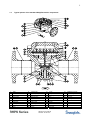
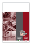
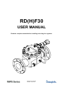
RD(H)F30
USER MANUAL
Read the complete manual before installing and using the regulator.
RD(H)F30 User Manual
Rev.date: 20-09-2010
WARNING
INCORRECT OR IMPROPER USE OF THIS PRODUCT CAN CAUSE SERIOUS PERSONAL
INJURY AND PROPERTY DAMAGE.
Due to the variety of operating conditions and applications for this product, the user is solely
responsible for making the final proper decisions concerning the correct assembly and functioning of
the product and assuring that all the performance, safety and warning requirements are met.
• Users must be trained and equipped for the handling, use and servicing of pressure products
and systems.
• Users must contact their gas or liquid supplier for specific safety precautions and instructions.
• Gaseous media should be free of excessive moisture to prevent icing at high flow.
• Always wear the appropriate protective clothing, including safety glasses, gloves etc. if required.
• Follow the applicable safety and maintenance procedures.
• Obey specific local regulations.
• Do not exceed the maximum inlet and outlet pressure of the product or its accessories.
• Operate within the temperature limits and other conditions specified for the product.
• Do not drop or damage the product in any other way. This may negatively effect the
performance of the product which can cause the product to malfunction.
• Venting fluids and gases can be dangerous. Vent to a safe environment away from people.
Ensure adequate ventilation.
• This product is not oxygen clean and therefore not suitable for oxygen service.
If there are questions or problems regarding the installation, operation and maintenance these should
be directed to the proper authority on site before continuing.
RD(H)F30 User Manual
Rev.date: 20-09-2010
CONTENTS
1 Introduction ..................................................................................................................................... 1 1.1 Detailed description ....................................................................................................................... 1 1.2 Special features and options ......................................................................................................... 1 1.3 Typical picture of the standard RD(H)F30 and its components .................................................... 2 2 Installation ....................................................................................................................................... 3 2.1 Points of attention before installation ............................................................................................ 3 2.2 Oxygen service ............................................................................................................................. 3 2.3 Installation instructions .................................................................................................................. 3 2.4 Filling the dome ............................................................................................................................. 4 2.5 External feedback ......................................................................................................................... 5 2.6 Connecting the external feedback ................................................................................................ 5 3 Operation ......................................................................................................................................... 6 3.1 Required tools for operation .......................................................................................................... 6 3.2 Points of attention before operation .............................................................................................. 6 3.3 Changing the set pressure ............................................................................................................ 7 4 5 Maintenance..................................................................................................................................... 8 4.1 Required tools for maintenance .................................................................................................... 8 4.2 Points of attention before removal from the system...................................................................... 9 4.3 Removal from the system ............................................................................................................. 9 4.4 Disassembly instructions............................................................................................................... 9 4.5 Inspection of disassembled parts .................................................................................................. 9 4.6 Points of attention before assembly .............................................................................................. 9 4.7 Assembly instructions ................................................................................................................... 9 4.8 Recommended torques ............................................................................................................... 10 4.9 Testing......................................................................................................................................... 10 4.9.1 Leakage across the seat ......................................................................................................... 10 4.9.2 Leakage across the diaphragm ............................................................................................... 10 Trouble shooting ........................................................................................................................... 11 RD(H)F30 User Manual
Rev.date: 20-09-2010
1
1 Introduction
1.1
Detailed description
This regulator is a diaphragm sensing dome loaded pressure regulator, designed for high pressure, high
flow gases and liquids.
The regulator comprises a body and dome bolted together and has a removable seat and valve.
The product is designed to be used between -20 °C and +80 °C, whether ambient temperature or media
temperature.
The regulator is soft seated for leak tight shut-off in zero flow conditions and is available in stainless steel.
The regulator is a dome loaded type, which means it must be connected to a controlled pressure source to
operate.
The maximum in- and outlet pressure for the models are, flange limits not included:
-
Flanged models RDF30
Flanged models RDHF30
: Inlet 70 bar
: Inlet 280 bar
Outlet 70 bar
Outlet 200 bar*
Check the assembly drawing or regulator for the specific pressure limits of the supplied
regulator.
* When using the RDHF30 with an inlet pressure higher than 200 bar, a safety valve must be
installed in the outlet line, because the outlet pressure may not exceed 200 bar.
Standard features:
diaphragm sensing
bubble tight shut-off
42mm valve
balanced valve
pilot regulator
dynamic regulation
1.2
Special features and options
The regulator is available with the following options:
external feedback
RD(H)F30 User Manual
Rev.date: 20-09-2010
2
1.3
1
2
3
4
5
6
7
8
9
10
Typical picture of the standard RD(H)F30 and its components
body
dome
bottomplate
valve case
valve screw
valve stem
bodyplate
domeplate
diaphragmplate
seat
11
12
13
14
15
16
17
18
19
20
valve spring
conical spring
guide ring
retaining ring
ring
socket head cap screw
valve insert
diaphragm
o-ring
o-ring
21
22
23
24
25
27
28
30
31
32
o-ring
o-ring
blindplug 1/4" bsp
ring
socket head cap screw
tube
flange
bonded seal
male connector
tube 3/8”
RD(H)F30 User Manual
Rev.date: 20-09-2010
33
34
35
36
37
bleedplug 1/4" bsp
dynamic regulation tube
male connector
tube 3/8”
pilot regulator
3
2 Installation
WARNING
A PRESSURE REGULATOR IS NOT A SHUT-OFF VALVE AND SHOULD NOT BE USED AS SUCH.
2.1
Points of attention before installation
This regulator can be equipped with different options and connections.
Before installing the regulator you should fully understand the options and the suitability of your particular
regulator and its suitability for the application.
-
-
2.2
-
The preferred mounting position of the regulator is horizontal with the dome facing upwards.
It may be necessary to remove the regulator from the system during maintenance or service.
Make sure that this is possible, especially if mounted in a different position.
The regulator is suitable for gases and liquids. Check if the materials on the assembly drawing,
which came with the regulator, are compatible with the used media.
SWAGELOK B.V. recommends not to use a self-venting version pilot regulator with hazardous or
toxic media.
If required take the necessary safety precautions to ensure a safe workspace and your personal
safety. Vent to a safe environment away from people and ensure adequate ventilation.
Avoid sealing compounds which harden, be careful with anaerobic (loctite type) compounds.
Particles of these compounds can run into the regulator and lock moving parts.
The product is designed to be used between -20 °C and +80 °C, whether ambient temperature or
media temperature. In all other cases consult SWAGELOK B.V..
The regulator is standard not oxygen clean. Although all regulators are ultrasonically cleaned, this
does not make them suitable for oxygen use.
Oxygen service
Specification of materials in regulators for oxygen service is the user’s responsibility. SWAGELOK
B.V. can perform cleaning for Oxygen service based on ASTM-G93LevelC/CGA4.1 at additional
cost.
2.3
Installation instructions
-
Verify that the regulator, the connections and its accessories are undamaged.
Verify that the regulator and its accessories are suitable for the system operating pressure and
have the proper connections.
Carefully clean all pipes and connections. Any swarf, lint, wire etc. may cause seat leakage.
Verify the flow direction of the system and mount the regulator accordingly.
Securely make the appropriate connections to the regulator in accordance with the procedures
recommended by the manufacturer of the connections.
Shut-off valves should be mounted in the system for service or maintenance.
At the time of delivery, every unused gauge connection is plugged with blind fittings.
Remove these and connect gauges if desired.
If earthing is required, connect an earth wire under a dome bolt.
-
RD(H)F30 User Manual
Rev.date: 20-09-2010
4
2.4
Filling the dome
The dome can be filled using manual or electronic loading.
Manual loading:
1.
This can be done by taking the gas pressure from the system and feeding this through a spring
loaded pilot regulator into the dome. This is shown in sketch A.
2.
In liquid systems the gas pressure for manual dome loading can be taken from a cylinder or
mains. This is shown in sketch B.
Substituting the spring loaded pilot regulator for a proportional control valve and a pressure sensor,
allows you to control the pressure electronically.
Electronic loading:
1.
This can be done by taking the gas pressure from the system and feeding this through a
proportional control valve into the dome. This is shown in sketch C.
This method can be used for low and medium pressure systems.
2.
This can be done by taking the gas pressure from the system and feeding this through a
proportional controlled ratio regulator into the dome. This is shown in sketch D.
This method can be used for high pressure systems.
The best results will be achieved by allowing a small flow to continuously pass through the pilot regulator.
This flow can either be vented or, in gas systems, fed back through an orifice into the downstream piping.
This is usually referred to as “dynamic regulation”.
It is not recommended to place a gauge on the dome to set or check the outlet pressure.
Because of forces in the regulator, the dome pressure will always be higher than the outlet
pressure. Place a gauge in the outlet line to set or check the outlet pressure.
RD(H)F30 User Manual
Rev.date: 20-09-2010
5
2.5
External feedback
When using the regulator with external feedback, option –EF, make sure that the outlet
pressure can be fed back to the external feedback connection before applying pressure to
the regulator. Failing to do so may lead to damage and non-functioning of the regulator as
the inlet pressure will be put straight through to the outlet.
The purpose of the external feedback on a pressure regulator is to get a more accurate regulation of the
outlet pressure. This can be achieved by sensing the outlet pressure downstream of the regulator and
feeding it back to the regulator. For this purpose SWAGELOK B.V. has provided a special connection,
marked on the regulator itself as "P2 feedback".
2.6
Connecting the external feedback
The external feedback must be installed as follows:
The external feedback is to be connected in a turbulence-free zone in the downstream piping, at a
maximum distance of 5x the outside diameter of the down stream piping.
The external feedback must be connected on top of the downstream piping.
The tube-size of the external feedback should be ⅜” or ½”.
Never connect the external feedback line downstream of a shut-off valve.
Principle sketch of external feedback:
RD(H)F30 User Manual
Rev.date: 20-09-2010
6
3 Operation
3.1
Required tools for operation
For changing the set pressure on a standard regulator, no tools are required.
3.2
Points of attention before operation
-
The product can be hot or cold, depending on the environment temperature and the used media
temperature. Take the necessary precautions before operating or touching the product.
SWAGELOK B.V. recommends not to use a self-venting version pilot regulator with hazardous or
toxic media.
If required take the necessary safety precautions to ensure a safe workspace and your personal
safety. Vent to a safe environment away from people and ensure adequate ventilation.
If the shut-off valve at the outlet side is closed after changing the set pressure, the outlet pressure
will rise a little because of the closing force required for bubble-tight closing of the regulator.
This phenomenon is usually referred to as the “lock-up” and does not indicate a problem with the
regulator.
A decrease in the flow will result in a rise of the outlet pressure.
An increase in the flow will result in a fall of the outlet pressure and is usually referred to as the
“droop”.
This phenomenon does not indicate a problem with the regulator.
A decrease of the inlet pressure will result in a rise of the outlet pressure.
An increase of the inlet pressure will result in a fall of the outlet pressure.
This phenomenon is usually referred to as the “dependency” and does not indicate a problem
with the regulator.
-
-
-
-
Each regulator type has its own dependency, which is related to the ratio between the effective seat area
and the sensing area. The approximate change can be calculated as shown below:
ΔP2 = ratio x ΔP1
A ratio of 1/X means that for every pressure change to P1 of X bar, the P2 pressure will change 1 bar:
RD(H)F30:
ratio = 1/118
Example:
Regulator with ratio 1/118
Start position:
P1 = 200 bar
P2 = 10 bar
End position
P1 = 20 bar
P2 = ?? bar
ΔP2 = ratio x ΔP1
ΔP2 = 1/118 x (200-20)
ΔP2 = 1,5 bar
So, as a result of a pressure drop in the inlet pressure from 200 to 20 bar, the outlet pressure will rise
from 10 bar to approximately 11,5 bar without adjusting the regulator.
If the pilot regulator also has changing inlet pressures, this will make the pressure
difference in the outlet line of the dome regulator even bigger. This is because the pilot
regulator will also increase it’s outlet pressure, which is the dome pressure.
Any rise to the dome pressure will result in a rise of the outlet pressure.
RD(H)F30 User Manual
Rev.date: 20-09-2010
7
3.3
Changing the set pressure
-
Check the supply of medium at the inlet side.
-
-
* When using the RD(H)F30 with an inlet pressure higher than 200 bar, a safety valve must
be installed in the outlet line, because the outlet pressure may not exceed 200 bar.
Make sure the inlet pressure is higher than the required outlet pressure and that the inlet pressure
does not exceed the maximum allowed inlet pressure. Open the shut-off valve at the inlet side.
Open the shut-off valve at the outlet side slightly to allow a minimal flow.
Controlled outlet pressure settings are obtained by adjusting the pressure in the dome. Increasing
the pressure in the dome raises the outlet pressure while decreasing the pressure in the dome
lowers the outlet pressure.
A shut-off valve on the outlet side must be opened to relief the pressure on the outlet side.
Final adjustment must be made while increasing the pressure in the dome to obtain the most
accurate set point(s).
Open the shut-off valve at the outlet side fully to allow full flow during operation.
RD(H)F30 User Manual
Rev.date: 20-09-2010
8
4 Maintenance
WARNING
INCORRECT OR IMPROPER REPAIR OR SERVICING OF THIS PRODUCT CAN CAUSE SERIOUS
PERSONAL INJURY AND PROPERTY DAMAGE.
SWAGELOK B.V. recommends the product to be removed from the system and to be shipped to
SWAGELOK B.V. for service or maintenance as all products must pass rigid acceptance tests before
leaving the factory.
All repairs and servicing of this product must be performed by factory certified personnel and tested for
operation and leakage.
If this procedure is not followed for any reason, or if any customer changes are made to the product,
SWAGELOK B.V. cannot assume responsibility for the performance or safety of a customer repaired
product or for any damage resulting from failure of the product.
The product should be checked periodically for proper and safe operation.
It is the users sole responsibility to determine the frequency of maintenance based on the application.
L RECOMMENDATION
SWAGELOK B.V. RECOMMENDS TO HAVE SPARE-PART KITS READILY AVAILABLE ON SITE.
All regulators require maintenance at scheduled intervals. Annual maintenance is recommended under
normal use.
From experience SWAGELOK B.V. can tell that especially during the start-up of a system, the demand
for spare-part kits is high.
This is despite all the effort taken to assure a clean system, there is usually some debris left in the
system, which damages the regulator.
Having spare-part kits on site will save time and money, as the downtime of the system will be reduced
to a minimum, whether during start-up or normal operation.
4.1
Required tools for maintenance
-
a vice to fasten the regulator
pincers to take out the o-rings
a pair of tongs for a retaining ring 140mm
a torque wrench
a torque wrench hexagon head key 10 and 14
media and temperature compatible lubricant for reassembling threaded parts
media and temperature compatible lubricant for o-rings
soapy water for leak-testing
RD(H)F30 User Manual
Rev.date: 20-09-2010
9
4.2
Points of attention before removal from the system
-
SWAGELOK B.V. recommends removing the regulator from the installation.
Make sure that a spare-part kit is present.
Check if the used media is hazardous or toxic.
If required take the necessary safety precautions to ensure a safe workspace and your personal
safety. Vent to a safe environment away from people and ensure adequate ventilation.
Follow your system safety, maintenance or special local procedures when removing the regulator.
The product can be hot or cold, depending on the environment temperature and the used media
temperature. Take the necessary precautions before operating or touching the product.
-
4.3
Removal from the system
-
Isolate the regulator from all pressure sources by closing the appropriate valves in the system.
Make sure there is no more pressure left in the dome.
If the pilot regulator is a self-venting version, the excess pressure in the dome will leave the
regulator through the relief connection.
Make sure that the inlet and outlet pressure are both reduced to zero.
-
A shut-off valve on the outlet side must be opened to relief the pressure on the outlet side.
4.4
Disassembly instructions
-
Loosen the hexagon socket head screws and remove the dome, dome plate, diaphragm and
diaphragm plate.
Loosen the hexagon socket head screws and remove the bottom plate, valve, valve spring and
seat.
-
4.5
Inspection of disassembled parts
-
Check all parts for abnormal wear. Replace parts in case of doubt.
4.6
Points of attention before assembly
-
All parts must be clean and undamaged before starting assembly.
SWAGELOK B.V. recommends replacing all o-rings and the diaphragm before assembly.
All threaded parts must be lubricated a little before assembly, this to avoid galling of threads.
All o-rings need to be lubricated a little to improve the lifetime of the o-ring and the performance of
the regulator.
4.7
Assembly instructions
Follow the points for disassembly in reverse order to assemble the regulator.
RD(H)F30 User Manual
Rev.date: 20-09-2010
10
4.8
Recommended torques
Only tighten the bolts or parts if the regulator is completely pressure less.
-
Hexagon socket head screws M12
Hexagon socket head screws M16
4.9
Testing
50 Nm
90 Nm
Check the regulator for leakage across the seat, with low- and high inlet pressure.
Check the regulator for leakage across the diaphragm, with low- and high outlet pressure.
* When using the RDHF30 with an inlet pressure higher than 200 bar, a safety valve must be
installed in the outlet line, because the outlet pressure may not exceed 200 bar.
4.9.1 Leakage across the seat
-
Make sure there is no more pressure in the dome.
Maintain a test pressure of approximately 5 bar on the inlet and check for leakage (bubbles) at the
outlet by using a little soapy water.
Repeat the procedure with the highest inlet pressure suitable for the regulator.
4.9.2 Leakage across the diaphragm
-
The outlet side and gauge connections must be plugged off bubble tight.
Maintain a test pressure of approximately 5 bar on the inlet and turn the adjustment knob of the
pilot regulator clockwise until you've reached 1 bar outlet pressure for the regulator.
Check the connection between body and dome for bubbles by using a little soapy water.
Repeat the procedure with the highest inlet- and outlet pressure suitable for the regulator.
A well performing RD(H)F30 is 100% bubble tight.
If there is a leakage across the seat or the diaphragm, the damaged parts must be replaced.
RD(H)F30 User Manual
Rev.date: 20-09-2010
11
5 Trouble shooting
Problem:
The outlet pressure creeps up, without increasing the dome pressure.
Cause:
A damaged valve and/or seat.
Solution:
Replace the valve and/or the seat.
Problem:
Leakage around the bottom plate.
Cause:
A damaged o-ring.
Solution:
Replace the o-ring.
Problem:
Leakage between the body and the dome.
Cause:
A damaged diaphragm or insufficient torque on the bolts.
Solution:
Replace the diaphragm or tighten the bolts according to the torque specifications.
Problem:
Controlled pressure drops off sharply even when the flow is within regulator capabilities.
Cause:
The systems filter element is clogged.
Solution:
Replace the system filter element.
Problem:
The required outlet pressure can not be reached.
Cause:
The inlet pressure to the dome regulator or to the pilot regulator is not high enough.
Solution:
Make sure that the inlet pressure to the dome regulator and to the pilot regulator is sufficient.
Problem:
The outlet pressure rises too much when going from a dynamic to a static situation.
Cause:
There is too much flow in the dynamic situation.
Solution:
A larger regulator is required.
Check the specific application data with the flow curves in our documentation, if available.
Problem:
The outlet pressure does not drop if the pressure in the dome is lowered.
Cause:
The regulator is non-venting.
Solution:
A shut-off valve in the outlet line must be opened to reduce the outlet pressure.
Problem:
The outlet pressure has changed without adjusting the dome pressure.
Cause:
Changes to the inlet pressure will result in changes to the outlet pressure.
A decrease of the inlet pressure will result in a rise of the outlet pressure.
An increase of the inlet pressure will result in a fall of the outlet pressure.
Solution:
Maintain a constant inlet pressure to the regulator. See section “operation” about dependency.
Warranty Information
Swagelok products are backed by The Swagelok Limited Lifetime Warranty.
For a copy, visit swagelok.com or contact your authorized Swagelok representative.
RD(H)F30 User Manual
Rev.date: 20-09-2010