1
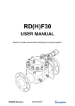
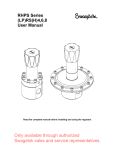
RS(H)2
USER MANUAL
(Also applicable for RD2 regulators)
Read the complete manual before installing and using the regulator.
RS(H)2, RD2 User Manual
Rev.date: 20-09-2010
WARNING
INCORRECT OR IMPROPER USE OF THIS PRODUCT CAN CAUSE SERIOUS PERSONAL
INJURY AND PROPERTY DAMAGE.
Due to the variety of operating conditions and applications for this product, the user is solely
responsible for making the final proper decisions concerning the correct assembly and functioning of
the product and assuring that all the performance, safety and warning requirements are met.
• Users must be trained and equipped for the handling, use and servicing of pressure products
and systems.
• Users must contact their gas or liquid supplier for specific safety precautions and instructions.
• Gaseous media should be free of excessive moisture to prevent icing at high flow.
• Always wear the appropriate protective clothing, including safety glasses, gloves etc. if required.
• Follow the applicable safety and maintenance procedures.
• Obey specific local regulations.
• Do not exceed the maximum inlet and outlet pressure of the product or its accessories.
• Operate within the temperature limits and other conditions specified for the product.
• Do not drop or damage the product in any other way. This may negatively effect the
performance of the product which can cause the product to malfunction.
• Venting fluids and gases can be dangerous. Vent to a safe environment away from people.
Ensure adequate ventilation.
• This product is not oxygen clean and therefore not suitable for oxygen service.
If there are questions or problems regarding the installation, operation and maintenance these should
be directed to the proper authority on site before continuing.
RS(H)2, RD2 User Manual
Rev.date: 20-09-2010
CONTENTS
1 Introduction .................................................................................................................................... 1 1.1 Detailed description ..................................................................................................................... 1 1.2
Special features and options ....................................................................................................... 1 1.3 Typical picture of the RS2 and its components ........................................................................... 2 2 Installation ...................................................................................................................................... 3 2.1 Points of attention before installation .......................................................................................... 3 2.2 Oxygen service ............................................................................................................................ 3 2.3 Installation instructions ................................................................................................................ 3 3 Operation ........................................................................................................................................ 4 3.1 Points of attention for changing the set pressure ........................................................................ 4 3.2 Required tools for changing the set pressure.............................................................................. 4 3.3
Changing the set pressure .......................................................................................................... 4 4 Maintenance ................................................................................................................................... 5 4.1 Points of attention for maintenance ............................................................................................. 5 4.2 Required tools for maintenance................................................................................................... 5 4.3 Blow off the system pressure ...................................................................................................... 5 4.4 Points of attention for disassembly .............................................................................................. 5 4.5
Disassembly ................................................................................................................................ 6 4.6 Inspection of parts ....................................................................................................................... 6 4.7 Points of attention for assembly .................................................................................................. 6 4.8
Assembly ..................................................................................................................................... 6 4.9
Recommended torques ............................................................................................................... 6 4.10
Testing ......................................................................................................................................... 7 5 Domeloaded version RD2(-DP) ..................................................................................................... 7 6 Trouble shooting ............................................................................................................................ 9 RS(H)2, RD2 User Manual
Rev.date: 20-09-2010
1
1
Introduction
The RS2 is a piston sensing spring-loaded regulator, for high pressure.
Seat, filter element and the unbalanced valve are mounted in an easy replaceable cartridge.
1.1
Detailed description
The RS2 is available in variable design with different options
Standard features:
ss 316L throughout
integral 25µm filter
piston sensing
bubble tight shut-off
6 outlet ranges
bottom mounting
The regulator is soft seated for leak tight shut-off in zero-flow conditions.
A pressure regulator is not a shut-off valve, SWAGELOK B.V. recommends to use always shut-off valves.
1.2
Special features and options
-
low torque no-wear stem.
captured vent below panel, ⅛"npt female connection on the body
low friction piston/piston plate for better control
cartridge valve assembly, easy replacement
panel mounting
non-relieving
RS(H)2, RD2 User Manual
Rev.date: 20-09-2010
2
1.3
Typical picture of the RS2 and its components
1
2
3
5
6
7
9
10
11
14
15
16
17
22
24
25
26
= body
= springhousing
= cartridge
= piston ring
= piston
= relief seat
= spring guide (bottom)
= spring guide (upper)
= set spring
= knob
= set screw
= springhousing cover
= C-ring
= O-ring
= O-ring
= O-ring
= O-ring
panel
panelring
mounting screw
RS(H)2, RD2 User Manual
Rev.date: 20-09-2010
3
2
Installation
WARNING
A PRESSURE REGULATOR IS NOT A SHUT-OFF VALVE AND SHOULD NOT BE USED AS SUCH.
2.1
Points of attention before installation
-
-
The RS2 is suitable for gases and liquids. Check the compatibility of the materials on the assembly
drawing sent with the regulator.
Check if the connection is fitted far enough into the regulator and check for leaking across the
fitting.
NEVER plug off the ⅛"npt female relief connection at the bottom of the body.
Avoid sealing compounds which harden, be careful with anaerobic (loctite type) compounds.
Particles of these compounds can run into the regulator and lock moving parts.
Frequent assembly and disassembly of the in- and outlet fittings can damage the in- and outlet
thread of the regulator. Damaged threads can cause serious injury.
The RS2-02 is not oxygen clean and is not suitable for oxygen use.
2.2
Oxygen service
-
Specification of materials in regulators for oxygen service is the user’s responsibility. SWAGELOK
B.V. can perform cleaning for Oxygen service based on ASTM-G93LevelC/CGA4.1 at additional
cost.
-
2.3
-
Installation instructions
Clarify the flow direction of the system and mount the RS2 accordingly.
The standard connection of the RS2 is ¼"npt female, to get a proper sealing across the fittings,
SWAGELOK B.V. recommends to use teflon tape.
At time of delivery, the gauge connections are plugged with ¼"npt blind fittings.
The RS2 can be mounted in two ways:
- panel mounting (to be ordered separately)
- bottom mounting
RS(H)2, RD2 User Manual
Rev.date: 20-09-2010
4
3
Operation
3.1
Points of attention for changing the set pressure
-
The adjustment knob is provided with an anti-turn out locking ring. Do not force it.
If the regulator is a non-relieving type, then a shut-off valve on the outlet side must be opened to
relief the pressure on the outlet side.
3.2
Required tools for changing the set pressure
Standard regulator:
For changing the set pressure at the standard regulator there are no tools necessary.
3.3
Changing the set pressure
-
Check the supply of medium at the inlet side.
Always adjust the regulator under flow conditions.
Turn the knob clockwise to obtain the required set pressure, or to increase the set pressure.
Decrease the set pressure by turning the knob counter clockwise, the excess pressure will leave
the regulator thru the 1/8" npt female connection in the bottom of the regulator (this is standard on
the RS2, non-venting is an option).
RS(H)2, RD2 User Manual
Rev.date: 20-09-2010
5
4
Maintenance
WARNING
INCORRECT OR IMPROPER REPAIR OR SERVICING OF THIS PRODUCT CAN CAUSE SERIOUS
PERSONAL INJURY AND PROPERTY DAMAGE.
SWAGELOK B.V. recommends the product to be removed from the system and to be shipped to
SWAGELOK B.V. for service or maintenance as all products must pass rigid acceptance tests before
leaving the factory.
All repairs and servicing of this product must be performed by factory certified personnel and tested for
operation and leakage.
If this procedure is not followed for any reason, or if any customer changes are made to the product,
SWAGELOK B.V. cannot assume responsibility for the performance or safety of a customer repaired
product or for any damage resulting from failure of the product.
The product should be checked periodically for proper and safe operation.
It is the users sole responsibility to determine the frequency of maintenance based on the application.
L RECOMMENDATION
SWAGELOK B.V. RECOMMENDS TO HAVE SPARE-PART KITS READILY AVAILABLE ON SITE.
All regulators require maintenance at scheduled intervals. Annual maintenance is recommended under
normal use.
From experience SWAGELOK B.V. can tell that especially during the start-up of a system, the demand
for spare-part kits is high.
This is despite all the effort taken to assure a clean system, there is usually some debris left in the
system, which damages the regulator.
Having spare-part kits on site will save time and money, as the downtime of the system will be reduced
to a minimum, whether during start-up or normal operation.
4.1
Points of attention for maintenance
-
SWAGELOK B.V. recommends to remove the regulator from the installation.
4.2
Required tools for maintenance
4.3
a vice to fasten the regulator
wrench nr. 36
wrench nr. 17
a pair of tongs for a circlip
different pair of tongs to remove the O-rings
Blow off the system pressure
Before starting the maintenance on the RS2 make sure there is no pressure left in the system, so
depressurize the in-and outlet side of the system, Check carefully!
4.4
-
Points of attention for disassembly
SWAGELOK B.V. recommends to remove the RS2 from the installation before starting with the
maintenance.
In every spare parts kit, the cartridge will be supplied as an assembly; individual parts cannot be
delivered.
RS(H)2, RD2 User Manual
Rev.date: 20-09-2010
6
-
4.5
4.6
4.7
4.8
The adjustment knob is provided with an anti-turn out ring. Do not force it!
Disassembly
Put the RS2 with the flat sides on the bottom into a vice, make sure it is secure.
Turn the adjustment knob counter clockwise until it blocks.
Remove the spring housing by turning it counter clockwise.
Remove the upper spring guide, set spring, bottom spring guide, piston and piston ring.
The cartridge with the valve, seat and filter element can now be removed.
Inspection of parts
Check all parts for abnormal wear. Replace all parts in case of doubt.
Points of attention for assembly
All parts must be clean and undamaged before starting the assembly.
SWAGELOK B.V. recommends to change all o-rings before assembly
All threads must be greased a little before assembly, this to avoid galling of threads.
Assembly
Follow the instructions in point 7.5 in reversed order to assemble the regulator
4.9
-
Recommended torques
springhouse cover in the spring housing
springhouse on the body
cartridge in the body
locking nuts in panel mount ring (if applicable)
RS(H)2, RD2 User Manual
Rev.date: 20-09-2010
70Nm.
70Nm.
30Nm.
30Nm.
7
4.10
Testing
Leakage across the seat
-
Turn the knob counter clockwise until it blocks.
Maintain a test pressure of approximately 5 bar on the inlet side and check for leakage (bubbles)
at the outlet port by using a bit of soapy water.
Leakage across the O-ring seals
-
The outlet side and gauge connections must be plugged off bubble tight.
Maintain a test pressure of approximately 5 bar on the inlet side, and turn the knob clockwise until
you have reached 5 bar at the outlet side as well.
Check the connection between body and spring housing, for bubbles by using the soapy water.
Do not forget the little relief hole in the spring housing.
Repeat the same procedure at higher pressures.
Check the required outlet pressure range
A well performing RS2 is 100% bubble tight.
If there is a leakage across the seat or the O-rings, the damaged parts must be replaced.
5
Domeloaded version RD2(-DP)
Domeloaded version RD2
-
-
Controlled outlet pressure settings are obtained by adjusting the pressure in the dome. Increasing
the pressure in the dome raises the outlet pressure while decreasing the pressure in the dome
coupled with venting of the piping on the downstream side of the regulator lowers the outlet
pressure.
Final adjustment must be made while increasing the pressure in the dome to obtain the most
accurate set point(s).
With flow, a minor drop in the controlled pressure will be observed which recovers when flow
ceases.
Differential pressure RD2-DP
Differential pressure is a combination of spring loading and dome loading.
Controlled outlet pressure settings are obtained by either adjusting the pressure in the dome or adjusting
the spring load.
RS(H)2, RD2 User Manual
Rev.date: 20-09-2010
8
RS(H)2, RD2 User Manual
Rev.date: 20-09-2010
9
6
Trouble shooting
Problem:
The outlet pressure creeps up, without turning the control knob.
Cause:
A damaged valve and/or seat.
Solution:
Replace the cartridge.
Problem:
Controlled pressure drops off sharply even when the flow is within regulator capabilities.
Cause:
The filter element is clogged.
Solution:
Replace the cartridge.
Problem:
Constant leak through the relief hole under the control knob
Cause:
A damaged relief valve seat, or the regulator is mounted in the wrong position
Solution:
Assemble a new relief valve seat, or mount the regulator in the right way
Problem:
The required outlet pressure can not be reached.
Cause:
The inlet pressure is not high enough.
Solution:
Make sure that the inlet pressure is sufficient.
Problem:
The outlet pressure rises too much when going from a dynamic to a static situation.
Cause:
There is too much flow in the dynamic situation.
Solution:
Check the specific application data with the flow curves in our documentation.
Problem:
The outlet pressure does not drop if the adjustment knob is turned counter clockwise.
Cause:
The regulator is non-venting.
Solution:
A shut-off valve in the outlet line must be opened to reduce the outlet pressure.
Problem:
The outlet pressure has changed without turning the adjustment knob.
Cause:
Changes to the inlet pressure will result in changes to the outlet pressure.
Solution:
Maintain a constant inlet pressure to the regulator.
Warranty Information
Swagelok products are backed by The Swagelok Limited Lifetime Warranty.
For a copy, visit swagelok.com or contact your authorized Swagelok representative.
RS(H)2, RD2 User Manual
Rev.date: 20-09-2010