1
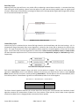
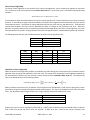
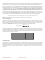
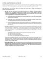
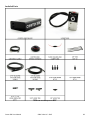
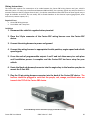
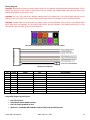
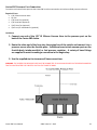
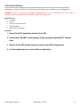
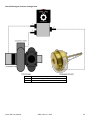
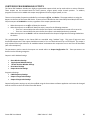
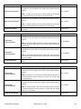
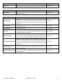
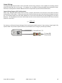
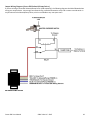
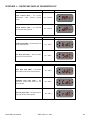
Wiring Instructions The Cortex EBC requires five connections to be made between the Cortex EBC wiring harness and your vehicle’s electrical system. On many cars manufactured between 1988 and 2007, the necessary signals can easily be found in a common location at the ECU (Engine Control Unit). On vehicles manufactured after 2007 some of these signals may no longer be available at the ECU, but can usually still be found elsewhere in the electrical system (gauge panel, other control units, sensors outputs, etc.). Required Parts Cortex EBC Wiring Harness Fuse Holder and 2 Amp Fuse Guidelines 1. Disconnect the vehicle’s negative battery terminal. 2. Place the 10-pin connector of the Cortex EBC wiring harness near the Cortex EBC device. 3. Connect the wiring harness to power and ground. 4. Connect the wiring harness to appropriate throttle position, engine speed and vehicle speed signals. 5. Cover the ends of programmable outputs 1 and 2 and tuck them away in a safe place until installation process is complete and the Cortex EBC has been setup for your vehicle. 6. Route the black sub-harness/connector into the engine bay to the location you plan to mount the 3-Port BCS. 7. Plug the 10-pin wiring harness connector into the back of the Cortex EBC device. The harness should be plugged in such that the purple, red, orange, and black wires are towards the TOP of the Cortex EBC device. Cortex EBC Wiring Harness Orientation (empty pin should be on top) Cortex EBC User Manual SIRHC Labs LLC - 2015 30