1
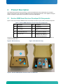
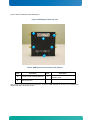
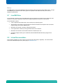
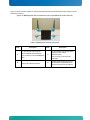
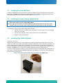
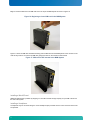
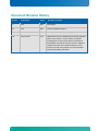
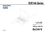
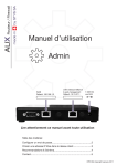
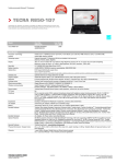
b Kontron M2M Smart Services Developer Kit User Manual Document Revision 1.06 » Table of Contents « 1 Introduction ........................................ 5 1.1 About this Manual ............................................................... 5 1.2 Manual Organization ............................................................. 5 1.3 Latest Versions of Product Documentation.............................................. 6 1.4 Safety Information ............................................................... 6 1.5 What Your Kontron M2M Smart Services Developer Kit Includes ............................. 6 1.6 Additional Third-party Software Options ................................................ 7 2 Product Description .................................. 8 2.1 Kontron M2M Smart Services Developer Kit Components ................................... 8 2.2 Kontron M2M System Panel Features ................................................ 10 2.3 Antennas ..................................................................... 16 2.4 Power Supply ................................................................. 16 2.5 System Cooling ................................................................ 16 2.6 Processor and Memory........................................................... 16 Processor ................................................................. 16 Memory ................................................................... 17 2.7 LiveUSB Drive ................................................................. 17 2.8 In-box Documentation ........................................................... 17 3 Component Installations .............................. 18 3.1 Before You Begin ............................................................... 18 Tools and Supplies Needed .................................................... 18 System References .......................................................... 18 3.2 Installing Antennas .............................................................. 18 3.3 Installing the LiveUSB Drive ....................................................... 20 3.4 Installing the power supply (power brick) .............................................. 20 3.5 Installing User Added Options ...................................................... 20 Installing a SIM Card ......................................................... 20 Installing a MicroSD card ...................................................... 21 Installing a Headphone ........................................................ 21 4 Operating Guide ................................... 22 4.1 Turning On the M2M System ...................................................... 22 4.2 Standalone Procedure ........................................................... 22 www.kontron.com www.kontron.com 4.3 Turning Off the M2M System ...................................................... 22 4.4 Indicator Lights ................................................................ 22 4.5 UEFI BIOS ................................................................... 23 4.6 Boot Loader Support ............................................................ 23 4.7 BIOS Operation & Adding Drivers ................................................... 23 4.8 Determining the BIOS Version ..................................................... 23 4.9 Changing the BIOS ............................................................. 24 4.10 Start AMI® Aptio Setup Utility ...................................................... 24 4.11 Wind River Bench top Procedure ................................................... 24 4.12 Drivers/Utilities/Command Support .................................................. 24 4.13 Web Server Utility to Get Going .................................................... 25 4.14 GUI for Connectivity ................................... Error! Bookmark not defined. 5 Drop-In PCI Express Mini Card 3G Module Installation ........ 27 5.1 3G- Enabled SKUs of the M2M System ............................................... 27 5.2 Addition/Replacement ........................................................... 27 5.3 Before You Begin ............................................................... 27 Tools and Supplies Needed .................................................... 27 System References .......................................................... 27 5.4 3G Installation Overview & Safety Information .......................................... 28 Overview .................................................................. 28 Safety Information ........................................................... 28 5.5 Removing the Chassis Cover ...................................................... 28 5.6 Removing the AV Card ........................................................... 29 5.7 Antenna Cable Routing .......................................................... 30 5.8 Attaching and Installing the Module .................................................. 31 5.9 Reattaching the AV board ......................................................... 33 5.10 Re-installing the Chassis Covers .................................................... 35 6 Troubleshooting .................................... 36 6.1 Resetting the System ............................................................ 36 6.2 Problems Following Initial System Installation .......................................... 36 First Steps Checklist .......................................................... 36 6.3 Hardware Diagnostic Testing ...................................................... 37 Confirming the Operating System Load ............................................ 37 6.4 Specific Problems and Corrective Actions ............................................. 37 Power Light does not Light ..................................................... 37 No Characters Appear on Screen ................................................ 37 www.kontron.com www.kontron.com Characters are Distorted or Incorrect .............................................. 38 Cannot Connect to a Kontron M2M System using Ethernet Connector ...................... 38 Diagnostics Pass but the Connection Fails .......................................... 38 Cannot Connect to a Kontron M2M System using Wi-Fi ................................ 38 Cannot connect to a Kontron M2M System using 3G .................................. 38 Problems with Newly Installed Application Software ................................... 39 Problems with Host Computer Display Accessing Demos and Tools on the LiveUSB Drive ....... 39 Problems with Application Software that Ran Correctly Earlier ............................ 39 7 Warranty ......................................... 40 Appendix A: Safety Information ............................ 41 A.1 Emissions Disclaimer .............................................................. 41 A.2 Intended Uses ................................................................... 41 Temperature and Ventilation .................................................... 41 A.3 Safety Cautions .................................................................. 41 Appendix B: Regulatory and Certification Information ............ 44 B.1 Product Regulatory Compliance ....................................................... 44 Product Safety Compliance ..................................................... 44 Product EMC Compliance - Class B Compliance ..................................... 44 Certifications/Registrations/Declarations ........................................... 44 B.2 Electromagnetic Compatibility Notices FCC (USA) ......................................... 44 B.3 European Community Compliance Statement ............................................. 45 B.4 Exposure to Radio Frequency Energy .................................................. 45 B.5 Additional Information .............................................................. 45 Appendix C: Getting Help ................................ 47 C.1 World Wide Web .................................................................. 47 C.2 Telephone ...................................................................... 47 C.3 Email .......................................................................... 47 Document Revision History ............................... 48 www.kontron.com www.kontron.com 1 Introduction 1.1 About this Manual Thank you for purchasing and using the Kontron M2M Smart Services Developer Kit. This manual is for smart services developers who are responsible for using the developer kit. This document provides a brief overview of the features of the system followed by a list of accessories or other components you may need or want to purchase, instructions for how to add or replace components in the M2M System and troubleshooting information. Kontron would like to point out that the information contained in this manual may be subject to technical alteration, particularly as a result of the constant upgrading of Kontron products. The attached documentation does not entail any guarantee on the part of Kontron with respect to technical processes described in the manual or any product characteristics set out in the manual. Kontron does not accept any liability for any printing errors or other inaccuracies in the manual unless it can be proven that Kontron is aware of such errors or inaccuracies or that Kontron is unaware of these as a result of gross negligence and Kontron has failed to eliminate these errors or inaccuracies for this reason. Kontron expressly informs the user that this manual only contains a general description of technical processes and instructions which may not be applicable in every individual case. In cases of doubt, please contact Kontron. This manual is protected by copyright. All rights are reserved by Kontron. Copies of all or part of this manual or translations into a different language may only be made with the prior written consent of Kontron. Kontron points out that the information contained in this manual is constantly being updated in line with the technical alterations and improvements made by Kontron to the products and thus this manual only reflects the technical status of the products by Kontron the time of printing. © 2012 by Kontron America, Inc. Printing and duplication, even of sections, is only permissible with the express approval of: Kontron America, Inc. NOTE: Always be sure to search for M2M System on the Support website at http://us.kontron.com/support/ for the latest version of this manual with possible updates since this version was published. 1.2 Manual Organization Chapter 2 Product Description The chapter provides a brief overview of the Kontron M2M Smart Services Developer Kit. In this chapter, you will find a list of the features, illustrations of the product, and product diagrams to help you identify components and their locations. Chapter 3 Component Installation The chapter provides instructions for adding components such as antennas and the LiveUSB drive. Use this chapter for step-by-step instructions and diagrams for installing components. Chapter 4 Operating Guide The chapter provides instructions for using the M2M System for software development. Utilities that are shipped with the system or that may be required to update the system are covered. This includes how to navigate through the BIOS (Basic Input/Output System) setup screens and how to perform BIOS updates. Chapter 5 Drop-In PCI Express Mini Card Module Addition/Replacement The chapter provides instructions for adding/replacing PCI Express cards and adding components such as the 3G module. Use this chapter for step-by-step instructions and diagrams for installing or replacing components. Chapter 6 Troubleshooting The chapter provides troubleshooting information. You will also find suggestions for performing troubleshooting activities to identify the source of a problem. 5 Chapter 7 Warranty The chapter provides the warranty information for the kit. Appendix A Safety Information The appendix provides the emissions disclaimer, power supply information, temperature and ventilation guidelines, and safety cautions in multiple languages. Appendix B Regulatory and Certification Information The appendix presents the regulatory and safety compliances and electromagnetic compatibility notices. Appendix C Getting Help The section details where the user can turn for assistance. 1.3 Latest Versions of Product Documentation This manual is for smart services developers who are responsible for using the developer kit. This document is a companion document to the Out-of-box Guide and the Getting Started Guide. The latest version of all documents is available for download from Kontron’s website using these links: General information for the kit is available in the “Downloads” area of the product page: http://us.kontron.com/products/systems+and+platforms/m2m/m2m+smart+services+developer+kit.html 1. This also is where you’ll fine any updated BIOS and Errata information. You will be asked to complete an information form in order to be granted access to the Errata and BIOS files. User manual (latest version of this manual): www.kontron.com/UserManualM2M Out of box guide: www.kontron.com/OutofboxguideM2M Getting started guide: www.kontron.com/gettingstartedguideM2M 1.4 Safety Information There is extensive safety information is included in the sections of this user manual were it is relevant. Both Appendix A and B of this manual focus on overall safety. Please read those sections and all warnings within the sections. 1.5 What Your Kontron M2M Smart Services Developer Kit Includes Your Kontron M2M Smart Services Developer Kit includes the following components: One M2M System preloaded with Wind River Linux 4.3 One power supply with US and Continental Europe power cords Two 802.11/802.15.4 antennas Two 3G antennas (only for SKUs including 3G option) LiveUSB drive with a 90-day trial of Wind River Workbench development tools See Chapter 3 & 4 for initial installation and configuration instructions. 6 Figure 1 shows the Kontron M2M Smart Services Developer Kit Box Figure 1. Kontron M2M Smart Services Developer Kit Box 1.6 Additional Third-party Software Options If you need more technical information or information about the accessories that can be used with the Kontron M2M Smart Services Developer Kit, refer to the Kontron M2M Technology webpage (http://us.kontron.com/simplify-andspeed-your-entry-into-the-m2m-marketplace/) for ecosystem partners. 7 2 Product Description This chapter briefly describes the main features of the Kontron M2M Smart Services Developer Kit. It provides a diagram of the product, a list of the Kontron M2M Smart Services Developer Kit features, and a diagram showing the location of important components and connections on the Kontron M2M System. 2.1 Kontron M2M Smart Services Developer Kit Components 1 Figure 2 and 3 show the Kontron M2M Smart Services Developer Kit with lid open to show the internal components. Table 1. Kontron M2M Smart Services Developer Kit Components Item Description Item Description A M2M System E LiveUSB drive B Power Supply F 3G antennas (selected SKUs only) C Continental power cord G 802.11/802.15.4 antennas D US power cord H Applicable in-box literature including an Out-of-Box Guide and Errata (as appropriate) Though not shown in the figures below, a microHDMI-to-HDMI cable is included with the kit as well along with any needed microUSB cables. Figure 2. Kit with the tray Figure 3. Kit without the tray H E F A G B C Figure 4: Kontron M2M System with 802.11/802.15.4 Antennas 8 D Table 2 summarizes the major features of the Kontron M2M Smart Services Developer Kit system. Table 2. Kontron M2M Smart Services Developer Kit Features Feature Chassis Dimensions (H x W x D)/Weight Interfaces Description 67mm x 100mm x 27mm (92mm x 100mm x 62mm) with mounting brackets/ 0.8 lb/0.36 kg system; 2.35 lb/1.1 kg packaged kit. These dimensions do not include the antennas or the antenna connectors SIM slot, USB 2.0, MicroUSB 2.0 host, Power, RJ-45 Ethernet, Microphone, Headphone/Line Out, 2x MicroHDMI, MicroSD slot, MicroUSB 2.0 client, 2x antenna connectors Controls Reset button, user input button (software-enabled) Internal Storage 4 GB via internal MicroSD card Expansion 100-240 Vac, 50/60 Hz input, 12 Vdc, 2A output (US and Continental Europe power cords included) Intel® Atom™ processor E620 (600MHz) or Intel® Atom® E640T (1 GHz)/Intel® Platform Controller Hub EG20T Intel® Centrino® Advanced N 6205 Wi-Fi module installed; TI cc2531 SOC, ready for ZigBee or 6LoWPAN” (note the ‘W’) or Wireless HART WPAN use; Ericsson F5521gw 3Gmodule installed or option to drop-in other PCI Express 3G/4G broadband module 1 PCIe Mini Card slot for WWAN 3G/4G broadband module (certification/drivers needed) or solid state disk addition Accelerometer Ultra low-power high performance three axis linear accelerometer Power supply Processor/chipset Radios 9 2.2 Kontron M2M System Panel Features Figure 5a. Kontron M2M System Overview Figure 5c. Kontron M2M System Label (Close-up of 2.25 in² label) 10 Figure 5c. Kontron M2M System Top View D C A E B Table 3 M2M system top and bottom view features Item Description Item Description A 3G/4G SIM slot D Client USB Port for Serial Redirection (selected SKUs only) B Reset button E Indicator Lights (11 in a row) For Reference: (left-to-right) Bi-color status LED, green disk activity LED, 3x WLAN LEDs, 3x WWAN LEDs, 3x WPAN LEDs C 11 Input button (software enabled) Figure 6. Kontron M2M System Bottom View As shown in Figure 6, there are mounting holes at each of the corners of the brackets. Figure 7. Kontron M2M System Ethernet/Power End View E C B D A F 12 Table 4. M2M System side view features Item Description Item Description A USB 2.0 Host Port for Serial Redirection (selected SKUs only) D USB 2.0 Host MicroUSB Port B Power E 2.4 GHz Antenna Connector (Primary 802.11/Wi-Fi Antenna); bottom connector is C RJ-45 Ethernet Port F Auxiliary 3G or Wi-Fi connector Note that a security slot also is accessible on the bottom of the system. Caution: The system supports USB OTG (On The Go) devices only when plugged into the host-only (or client-only) MicroUSB. Early vesions of the Kontron M2M development kit included a small slide switch near the MicroUSB Port to enable and disable 5V power to the MicroUSB Port. A nearby LED is green if 5V is enabled and amber if 5V is disabled. 13 Figure 8. M2M System AV End View F A C B D E G Table 5. M2M System other side view features Item Description Item Description A Headphone/Line Out Jack D Primary HDMI port (closest to the MicroUSB port) The secondary MicroHDMI port is closest to the antenna connector 14 B Microphone Jack E Client USB Debug Port (Reserved for Future Use) C MicroSD Slot F 2.4 GHz Antenna Connector (for 802.15.4/WPAN communications); G The primary 3G Antenna connector Figure 9 shows the label side of the M2M System. Figure 9. M2M System label side view A A B A A C Table 6. M2M System front and back panel features Item Description Item A Screws to hold mounting brackets” C B M2M System label Description Ventilation holes Note: Though not shown in the product image above, the Kontron M2M development unit also has a regulatory label affixed to this side of the system as well. 15 2.3 Antennas There are 2 antennas for 802.11 (WLAN) and 802.15.4 (WPAN) connectivity in each Kontron M2M Smart Services Developer Kit. If your kit also supports 3G connectivity there are an additional 2 smaller antennas for 3G connectivity. WARNING: The antennas supplied with the kit are the only antennas approved to be used with the device. Use of any other antennas will void the regulatory approvals. 2.4 Power Supply WARNING: The power supply included with the Kontron M2M Smart Services Developer Kit is 100-240 Vac, 50/60 Hz input, 12 Vdc, 2A output. A. No other power supply should be used beyond what has been provided with the kit. Use the appropriate cord for your geography. Any IEC320-C7 power cord with appropriate safety agency rating is acceptable for use, but do not use the IEC320-C7-PW cords that are squared on one side. Figure 13 shows the power supply and power cords supplied with the M2M System. Figure 10. M2M System power supply and power cords 2.5 System Cooling The system is passively cooled. There are no system fans. It is important that the M2M System have adequate ventilation so be careful when mounting the system to not block the vents on the label side of the system. 2.6 Processor and Memory Processor The M2M System in the Kontron M2M Smart Services Developer Kit board accommodates either a Intel® Atom® E620 (600MHz) or a Intel® Atom® E640T (1.0GHz) processor. For high volume M2M system production, other processor options are possible. 16 Memory The M2M System in the Kontron M2M Smart Services Developer Kit board supports 1GB of DDR2 memory. For high volume M2M system production other memory options are possible. Please discuss this with your Kontron or distribution representative. 2.7 LiveUSB Drive The LiveUSB drive included in the Kontron M2M Smart Services Developer Kit provides access to Wind River tools and demos. Set-up of the workbench environment for usage is explained in the section 3 of this manual. The LiveUSB drive contains: A fully configured and bootable version of the Fedora (Linux) operating system. The Wind River Linux platform, which includes the Wind River Workbench development suite and a board support package for the Kontron M2M System. Wind River documentation, including a Getting Started Guide. A set of guides which will lead you through the Wind River Linux evaluation. Wind River documentation for Wind River Workbench and Wind River Linux. A recovery image to allow you to rewrite the internal MicroSD with the factory image for the MicroSD. 2.8 In-box Documentation Documentation available in the box includes an Out-of-Box guide and Errata (as applicable). See the downloads section of the M2M Development Kit product page on www.kontron.com. 17 3 Component Installations This chapter covers installation of components included in the box and user added components that do not require removal of the chassis cover. All items covered in this section may be installed without opening the chassis. See section 6 for information about adding/replacing a 3G module. 3.1 Before You Begin Before working with your Kontron M2M Smart Services Developer Kit product, pay close attention to the safety instructions provided in this manual. See Appendix A. Tools and Supplies Needed No tools are needed System References All references to sides are consistent with Section 2 documentation. 3.2 Installing Antennas To install the antennas, remove them from the plastic covers and screw them into the antenna connectors. WARNING: The antennas supplied with the kit are the only antennas approved to be used with the device. Use of any other antennas will void the regulatory approvals. Figure 11 shows the M2M System and the 2x 802.11/802.15.4 antennas that accompany every SKU. Antennas should be screwed in to the top antenna connectors on either side of the systems. The antennas have an elbow so that the antennas can be aimed as needed or left straight. A good starting point is to aim both antennas up as shown in figure 13. The flexibility of being able to aim the antennas in different directions may be needed if the unit mounting necessitates antenna direction changes for improved coverage. 3G antennas (if provided as part of the SKU) should be connected to the bottom connectors. 18 Figure 11. M2M System with 2x Figure 12. M2M system with 2x 802.11/802.15.4 antennas 802.11/802.15.4 antennas installed Figure 13 shows both 802.11/802.15.4 antennas directed upward and the 3G antennas pointing outward. The 3G antennas do not bend. Figure 13. M2M System with all 4 antennas (only some SKUs have 3G antennas). C A B D D Table 7. M2M System antenna placement Item Description Item Description C 2.4 GHz Antenna Connector (primary antenna for 802.11/Wi-Fi communications) 2.4 GHz Antenna Connector (for 802.15.4/WPAN communications) A This connector is next to Headphone This connector is next to RJ-45 Jack B 19 Primary 3G Antenna Connector connector D Auxiliary 3G Antenna Connector (for selected SKUs only)/Auxiliary Wi-Fi Antenna Connector (for other SKUs) 3.3 Installing the LiveUSB Drive The Kontron M2M Smart Services Developer Kit comes with a USB drive that provides software demos that can be inserted into your workbench PC. Please see the Getting Started Guide available in the “downloads” section of the Kontron M2M Smart Services Development Kit product page on www.kontron.com. 3.4 Installing the power supply (power brick) WARNING: Do not attempt to modify or use an AC power cord set that is not the exact type supplied. Note that the power supply in the kit is a Delta EADP-24MB A. The power supply that accompanies the Kontron M2M Smart Services Developer Kit is the only one that should be used. Use of any other power supply invalidates the certifications and may be dangerous. To install the power supply (external power brick) follow these steps: 3.5 1. Attach the cord for your geography to the power supply. The power supply is external to the M2M system. It is a brick style. 2. Insert the power supply plug into the power socket on the top of the M2M System. 3. Plug in the cord to the wall socket. Installing User Added Options Installing a SIM Card Most countries worldwide have one or more operators that support 3G data services; please check with your local operator as to whether the operator supports HSPA, WCDMA or EDGE data services. All three are supported by the Ericcson F5521gw module. Please obtain your SIM from your local 3G operator (only selected custom SKUs from Kontron include a SIM). The SIM may be easily inserted in the slot on the top of the M2M System. A SIM card must be added to 3G M2M Systems to support 3G connectivity supplied by the Ericcson 5521gw module. To install your SIM card position the SIM so that the contacts are facing the non-labeled side of the M2M System as shown (with the contacts facing the headphone jack side of the system) . The notch in the SIM card should on the lower left as shown in Figure 15. Figure 15. Positioning of the SIM card pre-insertion in the M2M System 20 Begin to insert the SIM card in the SIM card slot on the top of the M2M System as shown in Figure 16. Figure 16. Beginning to insert SIM card in the M2M System Figure 17 shows the SIM card half inserted. Gently push the SIM card into the M2M System so the contacts on the card are fully inserted. To remove the SIM card gently push down on the card and it will uninstall. Figure 17. SIM card in half inserted in the M2M System Installing a MicroSD card Additional data storage is possible by dropping in a microSD card with storage capacity of up to 4GB in the slot on the side of the system. Installing a Headphone A headphone may be connected using the 3.5mm headphone jack provided. Use the correct connector size for the slot provided. 21 4 Operating Guide 4.1 Turning On the M2M System There is no on-off switch or button for the M2M System. To turn on follow these steps: 1. Connect the power cord appropriate for your geography to the power supply brick. 2. Connect the power supply brick to the M2M System. 3. Plug in the power cord to the wall outlet. 4. Note that the green indicator light is on. This light is located at the top of the system. 4.2 Standalone Procedure This procedure can be used with the minimum effort to verify that the Kontron M2M System is working. Configure the “bench top” as shown in 3.3e, but the LiveUSB drive and optional GUI Demo hardware will not be needed. Only the Ethernet and power connections are needed. (Ethernet cable must be provided by the developer). Power on the Kontron M2M System by attaching the power supply and cord to the system and plugging the system in. There is no on/off button. It has a default IP address of: 172.31.255.1 Configure the PC workstation (running Linux or other OS) to a static IP address of: 172.31.255.254 If running Linux on the PC, workstation runs the following: ssh –l root 172.31.255.1 When asked, enter the following password: root At this point you should be logged into the Kontron M2M System. 4.3 Turning Off the M2M System To turn off the M2M System, unplug it from the wall outlet. 4.4 Indicator Lights There are 10 indicator lights on the top surface. 1 bi-color status LED, which is green for disk activity From left to right in this order after the single bi-color status light: 22 green+yellow+red LEDs for WWAN (3G) green+yellow+red LEDs for WLAN (802.11) green+yellow+red LEDs for WPAN (802.15.4) 4.5 UEFI BIOS The M2M System uses a UEFI BIOS version 2.2 compliant with a boot loader. Some of the benefits of the Kontron M2M System include: Fast boot Static boot device override Support of LED, Push Button, GPIO bits through ACPI Tables You can update the Firmware using a Flash utility. 4.6 Boot Loader Support The boot loader is the power up firmware that loads first “main” executable block of code (bare bones BSP). The boot loader supports the following: USB-Keyboard during boot Booting from HDD/SDD connected to SATA or USB port Booting from Optical drive connected to SATA port Booting from either MicroSD Support Custom settings saved with Password Change boot order sequence by pressing hardware button at power on. Ability to update the BIOS/Firmware from the BIOS EFI Shell & DOS, Linux command line utility. Ability to save BIOS Configuration into a persistent Store USB/SATA/MicroSD. Through BIOS EFI Ability to load and save BIOS Configuration into a persistent Store USB/SATA/MicroSD. Through BIOS EFI Shell or DOS, Linux CLI Serial Port Redirection through USB7 Com port redirection to USB Port 4.7 BIOS Operation & Adding Drivers The M2M System uses the Kontron COMe-mTTi10 COM Express mini form factor pin-out type 10 computer-onmodule. Please refer to the user’s manual for that board to better understand standard BIOS operation and how to make changes. The computing board uses the AMI® Aptio, which is located in an onboard SPI serial flash memory. You can update the Firmware using a Flash utility. 4.8 Determining the BIOS Version The AMI® Aptio version is displayed in the main menu of the setup utility. » BIOS Vendor: American Megatrends » Core Version: x.x.x.x » BIOS Date: mm/dd/yyyy hh:mm:ss » BIOS Version: NTC1RXXX 23 4.9 Changing the BIOS The Aptio Setup Utility changes system behavior by modifying the Firmware configuration. The setup program uses a number of menus to make changes and turn features on or off. Functional keystrokes in POST: Enter Setup Enter Setup Boot Menu 4.10 Start AMI® Aptio Setup Utility To start the AMI® BIOS setup utility, press <DEL> or <F2> when the following string appears during boot up. Press <DEL> to enter Setup The Info Menu then appears. The Setup Screen is composed of several sections: Setup Screen Location Function o Menu Bar Top Lists and selects all top level menus. o Legend Bar Right side Bottom Lists setup navigation keys. o Item Specific Help Window Right side Top Help for selected item. o Menu Window Left Center Selection fields for current menu. Please refer to the COMe-mTTi10 User Manual for additional BIOS screen data and details on making changes. See: http://us.kontron.com/products/computeronmodules/com+express/com+express+mini/comemtt10.html 4.11 Wind River Bench top Procedure This procedure will pair the Kontron M2M system with the Wind River Workbench running on the PC workstation Configure the “bench top” setup shown in the drawing in this in section 3.3. Ensure that there is an active connection to the internet and that a DHCP server has provided local network addressing. The GUI Demo hardware is optional. 1. If desired, the LiveUSB drive can be inserted into either a Windows or Linux PC as a non-boot device so that the “Getting Started Guide” and other documentation can be reviewed before booting via the LiveUSB drive. The LiveUSB boot will not modify the current PC/workstation hard disk in any way (unless desired – see #5). 2. Before booting your host computer, ensure that the LiveUSB flash drive is correctly plugged into a USB port on the host computer. Switch on your host computer. You may have to interrupt the boot process in order to instruct the BIOS to boot from the LiveUSB flash drive instead of the internal hard drive. The host computer boots into a preconfigured Fedora environment. The LiveUSB has been tested with many different host computers. Although it will work with the majority of these, some computers contain hardware that is incompatible with the LiveUSB. If your host computer has a graphics controller that is not compatible with the default boot settings of the LiveUSB, you will see distorted graphics or possibly no graphics at all. For this case, an alternate boot option is available. Press any key to interrupt the default boot process. Use the down arrow key to select the ‗Alternate Boot option and press the ―Enter key. In many cases this alternate boot option will resolve issues with incompatible graphics drivers. If you continue to experience problems, you may wish to try a different host computer. 3. During the boot process, several software license screens will appear. These must be responded to and filled out in order for the 90-day trial period to become active. 4. After some evaluation, the LiveUSB boot image can be moved to hard disk for better performance. There is a menu selection on the Linux desktop under the ‘Applications→Wind River→’ dropdown menu to do this. 4.12 Drivers/Utilities/Command Support The M2M System supports the following drivers/commands: 24 OS Support BASE OS supporting standard On board hardware (details of the OS Ingredients to be added) Connectivity Drivers On Board Ethernet Driver (Intel® 82574) Intel 6205 ABGN WI-FI Driver (Infrastructure, Client and Ad Hoc Modes) Ericsson Modem Model F5521gw Driver On Board ZigBee Controller TI CC2531 Driver A/V Drivers Audio Driver Realtek ALC262-VC/ALC262-VD Support Mic In / Line Out Graphics Driver Intel® GMA 500, HDTV/HD capable, Decoder for MPEG2(HD)/H.264 Up to 256 MB, UM ITE IT6261 LVDS-HDMI video driver ITE IT6261 LVDS-HDMI audio driver (uses S/PDIF output from Realtek audio codec). Silicon Image Sil1392 video driver. Uses Intel SDVO drivers Silicon Image Sil1392 audio driver. Uses HDA input Other Drivers MicroSD Driver ST LIS331DLHTR accelerometer support cdc driver (to talk to USB devices [i.e., 802.15.4 radio] like serial devices) Commands, Utilities, etc. cc2531 firmware loader cc2531-related scripts and utilities PCA9555BS IO Expander for I²C. udev command (to allow static naming of USB devices, including 802.15.4 radio) Utility to read/write BIOS configurations from command line. Utility to update BIOS firmware from command line. Install from recovery USB.img to Micro SD 4.13 Web Management Utility A web management interface (WebIF), is provided in order to simplify provisioning of the system. Amongst other things, it allows you to configure and manage: 25 the IP and Network interface. the Wi-Fi connection the 3G Mobile connection the Zigbee connection. This provides basic functionality to start Zigbee as coordinator and search for devices to pair to. WebIF can be reached via any browser (for example, Mozilla or Chrome) from any PC or workstation that has a LAN (via the Ethernet port) or WiFi connection to the system. Access to WebIF is not available via the 3G port. WebIF defaults to the static IP address (192.168.1.1). If you connect via WiFi, the system will provide you (via DHCP) with a suitable IP address. If you are connecting via Ethernet, you will need to configure your Ethernet address appropriately (for example, use 192.168.1.2, netmask 255.255.255.0). Once connected, you can configure the systems interfaces a appropriate. The WebIF user id and password default to admin/admin. You should change this as soon as possible. 26 5 Drop-In PCI Express Mini Card 3G Module Installation 5.1 3G- Enabled SKUs of the M2M System Selected SKUs come with a pre-certified 3G module. This option makes it easier for development, testing and deployment in with some operators. A SIM card must be obtained from your local 3G provider. 5.2 Addition/Replacement If you purchased a Kontron M2M Smart Services Developer Kit that does not include the 3G module, the Ericsson F5521gw module may be added to the system since drivers are enabled and the BIOS supports this module. Please note that adding any other module will require additional drivers and certifications for the system. 5.3 Before You Begin Warning: Electrostatic discharge (ESD) and ESD protection: ESD can damage modems, boards, and other parts. We recommend that you perform all procedures in this chapter only at an ESD workstation. If one is not available, provide some ESD protection by wearing an antistatic wrist strap attached to chassis ground (any unpainted metal surface) on your Kontron M2M Smart Services Developer Kit when handling parts. Tools and Supplies Needed #1 and #2 Phillips (cross-point) screwdrivers (or interchangeable tip screwdriver with #1 and #2 Phillips bits) Torque screwdriver. Torque should be 1.5 inch/pound Personal grounding device such as an anti-static wrist strap and a grounded conductive pad (not shown) Ericsson F5521gw module System References All references to sides, top and bottom are defined earlier in this manual in section 2. 27 5.4 3G Installation Overview & Safety Information The following sections present general installation and removal procedures that are required to install a 3G modem in the M2M system. Overview To install the 3G modem you will need to remove the chassis cover, remove one of the system boards and a spacer piece, attach and install the modem and then reinstall the board previously removed. Then you must reattach the chassis cover. The spacer piece is not reinstalled. Safety Information The Kontron M2M System must be operated with the covers in place to ensure proper cooling. You will need to remove the front cover to add or replace components inside the chassis. CAUTION: The system must be disconnected from the power supply when adding components. Before removing either the mounting bracket or front cover, power down the Kontron M2M System by unplugging it from the wall outlet. A non-skid surface or a stop behind the Kontron M2M Smart Services Developer Kit may be needed to prevent the Kontron M2M System from sliding on your work surface. 1. Observe the safety and ESD precautions in Appendix A. 2. Turn off all peripheral devices connected to the Kontron M2M System. 3. Disconnect the power cord(s) to turn off the Kontron M2M System. 5.5 Removing the Chassis Cover The first step is to unscrew the chassis covers (5 total: 2 on top, 2 on bottom and 1 on side near audio jacks). Retain all screws for reassembly. The cover will not lift off since it is attached to the large panel without the label. Figures 18-20 show the start of removing the chassis cover. Figure 18. Unscrew the 2 top screws 28 Figure 19. Unscrew the 2 bottom screws Figure 20. Remove side screw Once the top and bottom chassis cover is unscrewed you can lift off the chassis cover including the top and bottom panels. Note: The cover needs to slide out slightly before lifting off the cover (the connectors extend into the thickness of the flange) Figure 21 shows the uncovered system and the removed chassis cover. Figure 21. M2M System and chassis cover 5.6 Removing the AV Card Remove the AV card as shown by unscrewing the 3 screws with a Phillips screwdriver. Retain the screws for reinstallation. Lift the card off the system and remove the spacer. The spacer is shown on the last photo of this section. Figure 22 shows the uncovered system and the AV card being unscrewed. 29 Figure 22. Remove AV card screw 5.7 Antenna Cable Routing At all times care must be taken not to alter the antenna cable routing. Altering the routing voids certifications. The following illustrations show the proper routing of antenna cables. Figure 23 shows antenna cable routing that that should be followed when the 3G module is installed. Figure 23. Antenna Cable Routing when there is no 3G module installed Figure 24 shows antenna cable routing that should be followed when the 3G modem is installed. Figure 24. Antenna Cable Routing supporting 3G Usage 30 5.8 Attaching and Installing the Module The white cord (antenna) from the top of the corner of the system must be attached to the 3G module following the antenna cable routing guide in section 5.7. Figure 25 shows attachment of the antennas to the 3G module. Figure 25. Attach the 3G module card Figure 26 shows the antennas properly attached to the 3G module. Figure 26. Attached 3G module card 31 The system includes a small circuit board spacer to position the AV board at the right height when no modem is installed. This spacer must be removed before the modem can be installed. Remove the screw that is holding the spacer as shown in Figure 27. Figure 27. Unscrew the screw prior to positioning the 3G module The next step is to position the 3G module inside the M2M System Figure 28 shows the positioning of the 3G module for installation. Figure 28. Position the module so that the screw holes are aligned Note: The 802.15.4 cable needs to be moved out of the way to insert the 3G modem, then placed on top of the 3G modem and around the AV connector prior to installing the AV board. The 802.15.4 cable may be a special filter cable; if this is a filter cable, it should be used on the 802.15.4 radio 32 Next, screw down the 3G module using a torque screwdriver (torque spec. 1.5 inch/pound) and the screw just removed. Only one corner of the module will be screwed into place, as depicted in Figure 29. Figure 29. Screw the 3G module into place 5.9 Reattaching the AV board Now position the AV board for re-attachment with the screw holes aligned to the screw holes on the boards below, as shown in Figure 30. Do NOT re-insert the spacer. It is no longer needed. Figure 30. Align the AV board for re-attachment 33 Next, use the torque screwdriver to attach all 3 screws as shown in Figure 31. Figure 31. Holding the AV board in place. Using a torque screwdriver (torque spec. 1.5 inch/pound) reseat the 3 screws to hold the AV board in place. Figure 32. The M2M System with the 3G module fully installed 34 5.10 Re-installing the Chassis Covers Follow this procedure (Using a torque screwdriver (torque spec. 1.5 inch/pound)) 1. 2. 3. 4. 5. Position the cover over the open unit so that the mounting brackets align and the top, bottom and side are aligned and ready for reassembly. Screw the 2 screws in the bottom using a Phillips screw driver. Screw the 2 screws in the top using a Phillips screw driver. Screw the 1 screw on the end using a Phillips screw driver. The finished unit should appear as below; note that the spacer is no longer installed in the M2M System. Figure 33. The M2M System with the 3G module fully installed and spacer removed Note: The cover needs to slide out slightly before lifting off the cover (the connectors extend into the thickness of the flange) 35 6 Troubleshooting This chapter helps you identify and solve problems that might occur while you are using the Kontron M2M Smart Services Developer Kit. For any issue, first ensure you are using the latest firmware and files. Available firmware upgrades include updates for BIOS and the baseboard management controller (BMC). Go to http://us.kontron.com/products/systems+and+platforms/M2M, click on downloads, BIOS for information about the latest updates. In addition to the Kontron M2M System firmware and files, also update any drivers used for components you have installed in your system, such as video drivers, network drivers, etc. drivers. If you are unable to resolve your Kontron M2M Smart Services Developer Kit problems on your own, see Section 10 for assistance contacts. 6.1 Resetting the System Before going through in-depth troubleshooting, first attempt to reset your system using one of the methods below. To do this: Press: Soft boot reset to clear the system memory and reload the operating system <Ctrl+Alt+Del> from the local keyboard connected to the M2M system Clear system memory, restart power-on self start test (POST), and reload the operating system Reset button Cold boot reset. Turn the system power off and then on. This clears system memory, restarts POST, reloads the operating system, and halts power to all peripherals Power on/off The M2M System has no Power button. The system must be plugged or unplugged to turn on/off. Power on/off or press the reset button near the LEDs on the top of the system. 6.2 Problems Following Initial System Installation Problems that occur at initial system startup are usually caused by an incorrect installation or configuration. Hardware failure is a less frequent cause. If the problem you are experiencing is with a specific software application, see “Problems with Newly Installed Application Software”. First Steps Checklist 36 Is power available at the source? Is the power supply plugged in? Check the power cable on the back of the Kontron M2M Smart Services Developer Kit and at the power source. Is the system power cord properly connected to the system? For systems with AC Power Modules, check to ensure power cord is properly plugged into a 5-15R outlet for 100-120V or a 6-15R outlet for 200-240V Are all cables correctly connected and secured? Are all peripheral devices installed correctly? Are all device drivers properly installed? This may be a problem if you have added a 3G module to the system that is not supported. Are the configuration settings made in Setup correct? Is the operating system properly loaded? Refer to the operating system documentation. 6.3 Hardware Diagnostic Testing This section provides a more detailed approach to identifying a hardware problem and locating its source. CAUTION: Turn off devices before disconnecting cables. Before disconnecting any peripheral cables from the system, turn off the system by unplugging the power cord, and any external peripheral devices. 1. Turn off the M2M system by unplugging the power cord and unplugging the power brick connector from system. Turn off and disconnect all external peripheral devices. Disconnect each of devices from the system, except for the keyboard and the video monitor. 2. Make sure your video display monitor and keyboard are correctly connected to the system. Turn on the video monitor. Set its brightness and contrast controls to at least two thirds of their maximum ranges (see the documentation supplied with your video display monitor). 3. Then make sure the M2M system power brick power cord is plugged into a properly grounded AC outlet. 4. This should turn on the system. If the power LED does not light, see Section below, “Power Light does not Light”. Confirming the Operating System Load Once the system boots up, the operating system prompt appears on the screen. The prompt varies according to the operating system. If the operating system prompt does not appear, see “No Characters Appear on Screen”. 6.4 Specific Problems and Corrective Actions This section provides possible solutions for specific problems: Try the solutions below in the order given. If you cannot correct the problem, contact your service representative or authorized dealer for help. See section 10 for contact information. Power Light does not Light Check the following: Did you plug in the system to the outlet? Have you securely plugged the Kontron M2M System power cord into the power supply brick? For AC, will other items plugged into the same power outlet function correctly? The LED light is surfaced mounted on the board. No Characters Appear on Screen Check the following: Is the keyboard functioning? Test it by turning the “Num Lock” function on and off to make sure the Num Lock light is functioning. Is the video monitor plugged in and turned on? If you are using a switch box, is it switched to the correct system? Are the brightness and contrast controls on the video monitor properly adjusted? Is the video monitor signal cable properly installed? Are you using a HDMI to DVI Adapter? Have you confirmed that it works by using it on another system? Does this video monitor work correctly if plugged into a different system? 37 The onboard video for the M2M system is automatic or LVDS and also depends on single or dual monitors option. Cards in the M2M System are anchored with screws. If one cards is loose, you may need torque screwdriver to ensure adequate tightening. To do this each card would have to be removed and then each reinstalled. Re-insert the cards one at a time with a reboot between each addition. Review the process in Section 5. Characters are Distorted or Incorrect Check the following: Are the brightness and contrast controls properly adjusted on the video monitor? See the manufacturer’s documentation. Are the video monitor’s signal and power cables properly installed? Does this video monitor work correctly if plugged into a different system? Cannot Connect to a Kontron M2M System using Ethernet Connector Make sure the network cable is securely attached at the connector port. Try a different network cable. Make sure you are using the correct and the current drivers. Go to downloads for the product: http://us.kontron.com/products/systems+and+platforms/M2M Make sure the driver is loaded and the protocols are bound. Make sure the correct networking software is installed. Diagnostics Pass but the Connection Fails Make sure the network cable is securely attached. Make sure you specify the correct frame type in your NET.CFG file. Cannot Connect to a Kontron M2M System using Wi-Fi Check to see if the Wi-Fi/3G indicator light is on. It should be red and be the third light on the top. It is surface mounted. When the light is on it is indicating that the Wi-Fi card in the system is functioning. Make sure that your Wi-Fi router is functioning and within range by confirming connectivity with another Wi-Fi device. Make sure you are using the correct and the current drivers. Go to downloads for the product: http://us.kontron.com/products/systems+and+platforms/M2M Make sure the driver is loaded and the protocols are bound. Make sure the correct networking software is installed. Cannot connect to a Kontron M2M System using 3G Make sure 3G signal is strong enough in your location by confirming 3G connectivity with another 3G device. Make sure SIM card is functioning by testing it in another system/phone. Make sure SIM card is fully inserted in the M2M System. This inserts from the top of the system. Check to see if the Wi-Fi/3G indicator light is on. It should be red and be the third light on the top. It is surface mounted. When the light is on it is indicating that the 3G modem card in the system is functioning. Make sure you are using the correct and the current drivers. Go to downloads for the product: http://us.kontron.com/products/systems+and+platforms/M2M Make sure the driver is loaded and the protocols are bound. 38 Make sure the correct networking software is installed. If you have added a pre-certified module to the system other than the Ericsson F5521gw, drivers must be added as part of the installation process. Problems with Newly Installed Application Software Problems that occur when you run new application software are usually related to the software, not the Kontron M2M System. Faulty equipment is unlikely, especially if other software runs correctly. Check the following: Make sure the system meets the minimum hardware requirements for the software. See the software documentation. Make sure the software is properly installed and configured for the system. See the software documentation. Use only an authorized copy. Unauthorized copies often do not work. Make sure the correct device drivers installed. If the problems persist, contact the software vendor’s customer service representative. Problems with Host Computer Display Accessing Demos and Tools on the LiveUSB Drive Please review the Getting Started Guide that is a document on the LiveUSB drive. There are troubleshooting sections in that document in case your host computer is having difficulty displaying content. Problems with Application Software that Ran Correctly Earlier Problems that occur after the system hardware and software have been running correctly sometimes indicate equipment failure. However, they can also be caused by file corruption or changes to the software configuration. Check the following: Uninstall and reinstall the software. Make sure all necessary files are installed. If the problems are intermittent, there may be a loose cable, dirt in the keyboard (if keyboard input is incorrect), a marginal power supply, or other random component failures. If you suspect that a transient voltage spike, power outage, or brownout might have occurred, reload the software and try running it again. Symptoms of voltage spikes include a flickering video display, unexpected system reboots, and the system not responding to user commands. NOTE: For AC power, if you are getting random errors in your data files, they may be getting corrupted by voltage spikes on your power line. If you are experiencing any of the above symptoms that might indicate voltage spikes on the power line, you may want to install a surge suppressor between the power outlet and the system power cord. Only use an IEC320-C7 power cord with the power supply provided in the kit. 39 7 Warranty This Kontron product is warranted against defects in material and workmanship for 2 years from the date of shipment. During the warranty period, Kontron will at its discretion decide to repair or replace defective products. Within the warranty period, the repair of products is free of charge as long as warranty conditions are observed. The warranty does not apply to defects resulting from improper or inadequate maintenance or handling by the buyer, unauthorized modification or misuse, operation outside of the product’s environmental specifications or improper installation or maintenance. Kontron will not be responsible for any defects or damages to other products not supplied by Kontron that are caused by a faulty Kontron product. Please use the following link for more information: http://us.kontron.com/support/rma-information/ 40 Appendix A: Safety Information Warning: This product has been designed for service development purposes. Although this product has already been approved by several agencies, compliance with your local regional rules may require additional EMC compliance testing. Before working with your Kontron M2M Smart Services Developer Kit, pay close attention to these safety instructions. You must adhere to the assembly instructions in this guide to ensure and maintain compliance with existing product certifications and approvals. Use only the described, regulated components specified in this guide. Use of other products / components will void the UL listing and other regulatory approvals of the product and will most likely result in noncompliance with product regulations in the region(s) in which the product is sold. This is an FCC (Federal Communications Commission) Class B device. A.1 Emissions Disclaimer To ensure EMC (Electromagnetic Compatibility) compliance with your local regional rules and regulations, the final configuration of your end system product may require additional EMC compliance testing. For more information, please contact your local Kontron Representative. See Appendix B, “Regulatory and Certification Information” for product Safety and EMC regulatory compliance information. This is an FCC (Federal Communications Commission) Class B device. A.2 Intended Uses This product was evaluated as Information Technology Equipment (ITE), which may be installed in offices, schools, computer rooms, and similar commercial type locations. The suitability of this product for other product categories and environments (medical, telecommunications, residential, alarm systems, etc.), other than an ITE application, may require further evaluation and additional certifications. WARNING: Do not attempt to modify or use an AC power cord set that is not the exact type supplied. Temperature and Ventilation CAUTION: Temperature -- The temperature, in which the Kontron M2M System operates when installed, must not go below 0°C or rise above 50°C. Extreme fluctuations in temperature can cause a variety of problems in your Kontron M2M System. CAUTION: Ventilation -- The M2M System equipment mounting location must provide sufficient airflow to the Kontron M2M System to maintain proper cooling. The mounting area must also include ventilation sufficient for exhaust of heat from the unit. Do not cover up air venting on the system. A.3 Safety Cautions Read all caution and safety statements in this document before performing any of the instructions. The power supply in this product contains no user-serviceable parts. 41 Do not attempt to modify or use the supplied AC power cord if it is not the exact type required. There is no power button on the M2M System. To remove AC power from the system, you must unplug each AC power cord from the wall outlet or power supply. The power cord(s) is considered the disconnect device to the main (AC) power. The socket outlet that the system plugs into must be installed near the equipment and must be easily accessible. SAFETY STEPS: If you remove the chassis cover to access the inside of the system, follow these steps: 1. Turn off all peripheral devices connected to the system. 2. Turn off the system by unplugging all AC power cords from the system or from wall outlets. 3. Disconnect the power supply from the system. 4. Label and disconnect all cables connected to I/O connectors or ports on the system. 5. Provide electrostatic discharge (ESD) protection by wearing an antistatic wrist strap attached to chassis ground of the system—any unpainted metal surface—when handling components. After you have completed the five SAFETY STEPS above, you can remove the system covers. To do this: 1. Remove and save all screws from the top and bottom covers as shown in Section 5 of the manual. 2. Remove the cover. 4. Do not operate the system with the chassis cover removed. For proper cooling and airflow, always reinstall the chassis covers before turning on the system. Operating the system without the covers in place can damage system parts. To install the covers: 1. Check first to make sure you have not left loose tools or parts inside the system. 2. Check that cables, add-in boards, and other components are properly installed. 3. Attach the covers to the chassis with the screws removed earlier, and tighten them firmly. 4. Attach the mounting brackets to the system with the screws removed earlier, and tighten them firmly. 5. Connect all external cables and the AC power cord(s) to the system. A microprocessor and heat sink may be hot if the system has been running. Also, there may be sharp pins and edges on some board and chassis parts. Contact should be made with care. Consider wearing protective gloves. 42 The M2M system in the development kit is designed to operate in a typical office environment. Choose a site that is: • Clean and free of airborne particles (other than normal room dust). • Well ventilated and away from sources of heat including direct sunlight. • Away from sources of vibration or physical shock. • Isolated from strong electromagnetic fields produced by electrical devices. • In regions that are susceptible to electrical storms, we recommend you plug your system into a surge suppressor. • Provided with a properly grounded wall outlet. • Provided with sufficient space to access the power supply cord(s), because they serve as the product’s main power disconnect. 43 Appendix B: Regulatory and Certification Information B.1 Product Regulatory Compliance Product Safety Compliance The Carrier Grade Kontron M2M Smart Services Developer Kit complies with the following safety requirements: Nemko NRTL 60950-1 (North America) EN60950-1 (Europe) IEC60950-1 (International), CB Certificate & Report including all international deviations Product EMC Compliance - Class B Compliance The Carrier Grade Kontron M2M Smart Services Developer Kit has been has been tested and verified to comply with the following electromagnetic compatibility (EMC) regulations. FCC /ICES-003 - Emissions (USA/Canada) CISPR 22 - Emissions (International) EN55022 - Emissions (Europe) EN55024 - Immunity (Europe) EN61000-3-2 - Harmonics (Europe) EN61000-3-3 - Voltage Flicker (Europe) CE- EMC Directive 89/336/EEC (Europe) Certifications/Registrations/Declarations Nemko NRTL (North America) CE Declaration of Conformity (Europe) FCC/ICES-003 Class B Verification Report (USA/Canada): S3IKM2M800 B.2 Electromagnetic Compatibility Notices FCC (USA) This device complies with Part 15 of the FCC Rules. Operation is subject to the conditions noted in the FCC Compliance Statement noted below. FCC ID number: S3IKM2M800 For questions related to the EMC performance of this product, contact: Kontron America, Inc. 14118 Stowe Drive Poway, CA 92064-7147 (888) 294-4558 FCC Compliance Statement This device complies with part 15 of the FCC rules. Operation is subject to the following two conditions: (1) this device may not cause harmful interference, and (2) this device must accept any interference received, including interference that may cause undesired operation. 44 Note: This equipment has been tested and found to comply with the limits for a Class B digital device, pursuant to part 15 of the FCC Rules. These limits are designed to provide reasonable protection against harmful interference in a residential installation. This equipment generates, uses, and can radiate radio frequency energy and, if not installed and used in accordance with the instructions, may cause harmful interference to radio communications. However, there is no guarantee that interference will not occur in a particular installation. If this equipment does cause harmful interference to radio or television reception, which can be determined by turning the equipment off and on, the user is encouraged to try to correct the interference by one or more of the following measures: Reorient or relocate the receiving antenna. Increase the separation between the equipment and receiver. Connect the equipment to an outlet on a circuit different from that to which the receiver is connected. Consult the dealer or an experienced radio/TV technician for help. Wireless Radio Use: This device is restricted to indoor use when operating in the 5.15 to 5.25 GHz frequency band. Cet appareil doit être utilisé à l’intérieur. Canadian Compliance Statement Complies with the Canadian ICES-003 Class B specifications. This device complies with Industry Canada license exempt RSS standard(s). Operation is subject to the following two conditions: (1) this device may not cause interference, and (2) this device must accept any interference, including interference that may cause undesired operation of the device. B.3 European Community Compliance Statement The equipment complies with the RF Exposure Requirement 1999/519/EC, Council Recommendation of 12 July 1999 on the limitation of exposure of the general public to electromagnetic fields (0–300 GHz). This wireless device complies with the R&TTE Directive. Hereby, Kontron AG declares that this cellular, Wi-Fi and 802.15.4 device is in compliance with the essential requirements and other relevant provisions of Directive 1999/5/EC. B.4 Exposure to Radio Frequency Energy The Kontron M2M System contains radio transmitters and receivers. When on, the System sends and receives radio frequency (RF) energy through its antenna. The Wi-Fi and 802.15.4 antennas are located attached to the system. The Kontron M2M System has been tested and meets the RF exposure requirements for Wi-Fi and 802.15.4 operation. Two cellular antennas are attached to the Kontron M2M System with the 3G option. For optimal mobile device performance and so that human exposure to RF energy does not exceed the FCC, IC, and European Union guidelines, always follow these instructions and precautions: Orient the device with the cellular antenna (located In either side of the device away from your body or other objects. You can further limit your exposure to RF by limiting the amount of time using the M2M System, since time is a factor in how much exposure a person receives, and by placing more distance between your body and the M2M system since exposure level drops off dramatically with distance. B.5 Additional Information For more information from the FCC about exposure to RF energy, see: www.fcc.gov/oet/rfsafety The FCC and the U.S. Food and Drug Administration (FDA) also maintain a consumer website at www.fda.gov/RadiationEmittingProducts/Radiation EmittingProductsandProcedures/HomeBusinessandEntertainment/CellPhones/default.htm to address inquiries about the safety of mobile phones. Please check the website periodically for updates. For information about the scientific research related to RF energy exposure, see the EMF Research Database maintained by the World Health Organization at: www.who.int/emf 45 Radio Frequency Interference Radio-frequency emissions from electronic equipment can negatively affect the operation of other electronic equipment, causing them to malfunction. Although the M2M System is designed, tested, and manufactured to comply with regulations governing radio frequency emission in countries such as the United States, Canada, the European Union, the wireless transmitters and electrical circuits in the M2M System may cause interference in other electronic equipment. Therefore, please take the following precautions: 46 Aircraft Use of M2M System may be prohibited while traveling in aircraft. Vehicles Radio frequency emissions from M2M System may affect electronic systems in motor vehicles. Pacemakers -- The Health Industry Manufacturers Association recommends that a minimum separation of 15 cm (6 inches) be maintained between a handheld wireless phone and a pacemaker to avoid potential interference with the pacemaker. Other Medical Devices -- If you use any other personal medical device, consult the device manufacturer or your physician to determine if it is adequately shielded from radio frequency emissions. Health Care Facilities -- Hospitals and health care facilities may use equipment that is particularly sensitive to external radio frequency emissions. Blasting Areas and Posted Facilities – Follow site regulations for RF devices Appendix C: Getting Help C.1 World Wide Web Technicians and engineers from Kontron and/or its subsidiaries are available for technical support. We are committed to making our product easy to use and will help you use our products in your systems. Please consult our Web site at http://us.kontron.com/support for the latest product documentation, utilities, drivers and support contacts. C.2 Telephone (800) 480-0044 C.3 Email [email protected] 47 Document Revision History Revision Publish Date Author 1.0 2011 Staff Initial release 1.04 2011 Staff Technical updates throughout 1.05 15-March-2012 CAV Technical and cosmetic updates throughout 1.06 20-June-2012 CAV Updated kit box picture. Modified page numbering. Adjusted product name reference. Various updates to Chapter 1 includingrespect to URLs where reference information is downloadable and what items are part of the kit. Additional updates where made to the detailed callouts for system connectors as well as temperature use recommendations. Improved LED labeling information. 48 Summary of updates Corporate Offices Europe, Middle East & Africa North America Asia Pacific Oskar-von-Miller-Str. 1 14118 Stowe Drive 17 Building, Block #1, ABP. 85386 Eching/Munich Poway, CA 92064-7147 188 Southern West 4th Ring Germany USA Road Tel.: +49 (0)8165/ 77 777 Tel.: +1 888 294 4558 Beijing 100070, P.R.China Fax: +49 (0)8165/ 77 219 Fax: +1 858 677 0898 Tel.: +86 10 63751188 [email protected] [email protected] Fax: +86 10 83682438 [email protected] 49