1
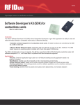
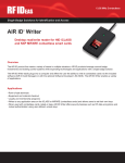
Ethernet 241 Discovery Tool User Manual V1.1 Rev A Thank You! Congratulations on the purchase of your Ethernet 241 device and Discovery Tool. RF IDeas hopes you enjoy using our products as much as we enjoyed creating and developing them. Configuration is easy, so you will be able to quickly take advantage of a more secure environment in your business, school, or organization. Visit www.RFIDeas.com and follow the Support Learning Center link for more details about our additional product lines. We look forward to your comments and suggestions for our various product lines. We are always discovering new applications and have several software developer’s licensing our technology so the solution you are looking for may already be developed. Please call our sales department if you have any questions or are interested in our OEM or Independent Developer’s programs. Thank you, The RF IDeas Staff Need Assistance? Ph: 847.870.1723 Fx: 847.483.1129 E: [email protected] [email protected] ©2014 RF IDeas Inc. Configuration User Manual Page | 2 Information Symbols Symbol Meaning Note Tip Important ©2014 RF IDeas Inc. Definitions Notes refer to useful information related to the text. Tips can provide hints and pointers in addition to the text. Important information can include prerequisites, limitations or cautions. Configuration User Manual Page | 3 Contents Information Symbols 3 Chapter 1. General Overview 5 1.1 Discovery Tool Basics..........................5 Chapter 3. Appendix A .......................12 3.1 Ethernet 241 Configuration Commands ................................................................12 1.2 System Requirements.........................5 1.3 Installation ..........................................6 Chapter 2. Operation .7 2.1 Standard Operation.............................7 2.2 Find All 241 Devices ...........................8 2.3 Load and Save List of Ethernet 241 Devices.....................................................8 2.4 Current Settings...................................9 2.5 Configuration Settings.........................9 2.6 Weblink Interface.................................9 2.7 Update Configuration...........................9 2.8 Update Firmware ..............................11 ©2014 RF IDeas Inc. Configuration User Manual Page | 4 Chapter 1. General Overview 1.1 Discovery Tool Basics The Discovery Tool is a PC-based GUI application that locates all Ethernet 241 devices on the local network and display basic information on each of them. The communication between device and network is made possible through the use of the discovery request/response message built into Ethernet 241 devices (includes 241 USB/Serial and 241 Serial). These messages are part of the public API. Image 1: pcProx Plus PoE for PLCs Configuration 1.2 System Requirements • Any 32-bit or 64-bit Windows computer should be sufficient for running the Discovery Tool. (It has been tested most extensively on Windows XP and Windows 7.) • The Discovery Tool needs access to the network that the Ethernet 241 devices are on. It uses UDP broadcast messages on the local network and ports 50000 and 11000. Broadcast messages are not typically passed through routers or virtual LANs. Optionally using a stored file of IP addresses for Ethernet 241 devices will eliminate the need for broadcast messages, but requires that the IP addresses are already known. ©2014 RF IDeas Inc. Configuration User Manual Page | 5 1.3Installation It is recommended that the Discovery Tool be installed using the setup.exe file. It will load .Net 4 if needed (compatible with both 32 bit and 64 bit machines). A 241 Discovery Tool entry in the RFIDeas folder in the Start Menu will be created. Installation steps: 1. Load the “241_DiscoveryTool_v1.4.2_install.zip” file onto the desired PC 2. Extract the files from the zip file. 3. Double-click on setup.exe 4. The 241 Discovery Tool will now be available from the Start Menu, under the RFIDeas folder. ©2014 RF IDeas Inc. Configuration User Manual Page | 6 Chapter 2. Operation 2.1 Standard Operation Version 1.4.x of the GUI has several buttons, a text entry field, a DataGrid to display a list of the Ethernet 241 devices, and two text boxes to display more information about a selected 241, or for minor status updates when not in use. Image 2: Discovery Tool GUI Only one instance of the Ethernet 241 Discovery Tool can be active on a PC at a time. An attempt to start a second instance will result in an error message and the second instance will not start. The startup message in the Details box, will read: Ready to listen on <ip address>:<port>. The IP address must be on the same network that the 241 devices are on. If there are multiple network adapters active on the PC, the 241 Discovery Tool will prompt the user as to which network adapter card should be used. ©2014 RF IDeas Inc. Configuration User Manual Page | 7 2.2 Find All 241 Devices The “Find All 241 Devices” button will return all the Ethernet 241 devices on the local network. Click on a particular device to see detail on it. If it is an Ethernet 241 USB/Serial, a web link will be active to the device’s web server page. The tool stores the current settings of each 241 device locally. If something changes, such as a configuration or firmware update, this process should again be executed so the tool can look once more for the Ethernet 241 USB/Serial devices and refresh the local copies of the 241 current settings. As this method uses UDP broadcast messages, it may not find 241 units that are behind a router or virtual LAN. In this case a text file containing a list of IP address will need to be used (see the next section). 2.3 Load and Save List of Ethernet 241 Devices The “Save list of 241 devices” allows for the current list of Ethernet 241 device(s) found in the DataGrid to be saved to a plain text file. The text file has a line for each Ethernet 241, and each line starts with the IP address. This information is all that is used in the load operation, but for convenience, the tool adds on the MAC address and optional location text field as comments for each line. Alternatively, an administrator could build a list of Ethernet 241 devices, by listing out the known IP addresses (one per line) for the 241s in the system. This could be useful if the devices are behind routers or virtual LANs, where a broadcast UDP message is not propagated. In this case the IP addresses must first be collected manually, one way is by using the recessed side button on the Ethernet 241 USB/Serial. • Pressing the button for more than 5 seconds after the unit is up and operational will result in a page being printed on an attached printer, containing vital information about the Ethernet 241, including its IP address. Clicking on the “Load list of 241 devices” button will cause the tool to read a file of IP addresses, and will send a discovery message to each Ethernet 241 individually. As this does not use a broadcast message, it will pass through routers and virtual LANs. ©2014 RF IDeas Inc. Configuration User Manual Page | 8 Sample content of a file with a list of 241 devices: List of 241’s One per line. Only the IP address is read by the 241 Discovery Tool. Anything other than a period, space or number starts a comment. 10.10.12.240 # Mac:68:AB:8A:00:00:47, Location: 10.10.12.241 # Mac:68:AB:8A:00:00:84, Location: 10.10.12.242 # Mac:68:AB:8A:00:00:7C, Location: HP Color LaserJet 10.10.12.243 # Mac:68:AB:8A:00:00:F4, Location: 10.10.12.244 # Mac:68:AB:8A:00:00:6E, Location: Kellyann’s Desk 10.10.12.245 # Mac:68:AB:8A:00:00:80, Location: 10.10.12.246 # Mac:68:AB:8A:00:00:0E, Location:241testing 2.4 Current Settings The current settings, or details text box, shows more detail of the selected Ethernet 241 (the row that is highlighted in the DataGrid). These are the current operating values, and with firmware version 2.02 or later, the firmware version is also shown. The values are stored in memory when the discovery message is sent to the Ethernet 241 units. If a 241 device has been changed, the list in the DataGrid needs to be updated. 2.5 Configuration Settings On Ethernet 241 USB/Serial units with firmware version 2.02 or later, the configuration settings are visible. This is effectively the same as the “show all” response in the command line interface on the Ethernet 241 Serial (via serial port or telnet connection). 2.6 Weblink Interface The Ethernet 241 USB/Serial has an available web interface. If a 241 USB/Serial device is selected in the DataGrid, the “Visit web configuration page” link is enabled. Clicking on this link will open a page on the default web browser, to the IP address of the 241 USB/Serial. 2.7 Update Configuration The configuration can be updated on one or more Ethernet 241 USB/Serial units (use the check ©2014 RF IDeas Inc. Configuration User Manual Page | 9 box in the first column, or Select All and Select None buttons). This can include the configuration of an attached serial or USB based RF IDeas card reader. For instance, this can be used for setting a reader for a particular card type. The URL and file name of the configuration file needs to be entered in the upper right text box, in the same format as a web browser would access the file (http://<domain_name>/<path>/<filename>). Then click the “Configure 241 Devices” button. The complete list of commands for configuring Ethernet 241 USB/Serial devices are in the appendix. The commands for updating a reader can be found in the Ethernet 241 USB/Serial documentation. HTML file example: <html><body> This is a sample configuration file, in HTML format.<br> <!-***************************************************************** * Put this file at a location accessible via the local network * (such as http://10.x.x.x/241web/DemoConfig.html) * This location is then entered in the “URL & file name” field * of the 241 Discovery Tool * This is not an exhaustive list of available commands * * The section inside the RFID tags cannot include any html tags! ***************************************************************** --> <RFIDeas241> 241:location=241 test unit 241:dns1_addr=10.11.12.13 241:dns2_addr=10.12.14.16 241:gw_addr=10.10.11.12 241:baud_rate=1 241:serv_client=1 241:init_serv_url=http://www.rfideas.com 241:init_str=/241web/vtLed.php?version=$9 241:init_retry_count=42 241:init_long_beep=1 241:init_short_beep=3 241:data_serv_url=http://www.rfideas.com 241:data_str=/241web/vtBeep.php?version=$9 241:data_long_beep=2 241:data_short_beep=4 </RFIDeas241> <RFIDeasACPUSB> rfid:beep.now=2 setdelay(500) rfid:out.led=2 rfid:out.led=0 rfid:out.led=255 </RFIDeasACPUSB> <RFIDeasACPSerial> rfid:beep.now=101 </RFIDeasACPSerial> <br> And end the html mode </body></html> ©2014 RF IDeas Inc. Configuration User Manual Page | 10 The ip_addr_mode setting needs a brief description here. It can be set to DHCP, in which case the gw_addr, dns1_addr, dns2_addr and ip_addr settings are ignored. Those settings are used if ip_addr_mode is set to static. The Ethernet 241 USB/Serial devices by default are set to DHCP for quick installation. If it is desired to ‘lock’ the settings assigned by the DHCP server, the transitional state of DHCP_to_static can be used for the ip_addr_mode. This will copy the current settings for ip_ addr, gw_addr, dns1_addr and dns2_addr into the configuration, and sets the ip_addr_mode to static. The unit still needs to be updated and rebooted for the settings to take effect as static IP addresses. 2.8 Update Firmware The firmware of an Ethernet 241 USB/Serial running v2.02 or later can also be updated by the Discovery Tool. Earlier versions must be updated through the web interface, in the Systems tab. 1. Select the units as described in section 2.7. 2. Enter the URL and file name in the available text box. The file must be an image file from RF IDeas, ending with *_APP.s19. 3. Click on the “Upgrade Firmware” button. After about 30 seconds, a confirmation that the unit has been updated will appear. 4. Give the devices an additional 15 seconds to reboot and then update the DataGrid. The new firmware version numbers will now be displayed in the Current Settings text box when the Ethernet 241 USB/Serial is selected. ©2014 RF IDeas Inc. Configuration User Manual Page | 11 Chapter 3. Appendix A 3.1 Ethernet 241 Configuration Commands ©2014 RF IDeas Inc. Configuration User Manual Page | 12 RF IDeas Inc. © 2014 RF IDeas. All rights reserved. Specifications subject to change without notice. Windows, Macintosh, Solaris, Sun Ray and Linux are trademarks of their respective companies. All other trademarks, service marks and product or service names are property of their respective owners. Mention of third-party products is for informational purposes only and constitutes neither an endorsement nor a recommendation. RF IDeas assumes no responsibility with regard to the performance or use of these products. All understandings, agreements, or warranties, if any, take place directly between the vendors and the prospective users. Please feel free to call, e-mail or visit our web site for a full list of applications, products, configuration options, supported cards and form factor specifications. Our web site includes application videos, support materials, case studies and detailed information about our product line. Every effort has been made to ensure that the information in this manual is accurate. RF IDeas is not responsible for printing or clerical errors.