1
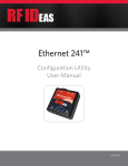
Ethernet 241™
USB/Serial Configuration Utility
User Manual
99009190 H
Thank You!
Congratulations on the purchase of your Ethernet 241™ device. RF IDeas hopes you enjoy using our
products as much as we enjoyed creating and developing them. Configuration is easy so you will be
able to quickly take advantage of a more secure environment in your business, school, or
organization.
Visit www.RFIDeas.com and follow the Support a Learning Center link for more details about our
additional product lines.
We look forward to your comments and suggestions for our various product lines. We are always
discovering new applications and have several software developers licensing our technology so the
solution you are looking for may already be developed.
Please call our sales department if you have any questions or are interested in our OEM or
Independent Developer’s programs.
Thank you,
The RF IDeas Staff
Need Assistance?
Ph: 847.870.1723
Fx: 847.483.1129
E: [email protected]
[email protected]
2
END-USER LICENSE AGREEMENT
LICENSE AGREEMENT
End-User License Agreement for RF IDeas™ SOFTWARE and HARDWARE - RF IDeas’ pcProx®, Proximity Activated Readers, Software
Developer’s Kit, and Proximity Reader DLLs, and Protocol(s).
IMPORTANT-READ CAREFULLY: This End-User License Agreement (“EULA”) is a legal agreement between you (either an individual or
a single entity) and the manufacturer RF IDeas (“Manufacturer”) with which you acquired the RF IDeas software and hardware product(s)
identified above (“PRODUCT”). The PRODUCT includes the RF IDeas reader, computer software, the associated media, any printed
materials, and any “on line” or electronic documentation. The SOFTWARE PORTION OF THE PRODUCT includes the computer software,
the associated media, any printed materials, and any “on line” or electronic documentation. By installing, copying or otherwise using the
PRODUCT, you agree to be bound by the terms of this EULA. If you do not agree to the terms of this EULA, RF IDeas is unwilling to license
the PRODUCT to you. In such event, you may not use or copy the SOFTWARE PORTION OF THE PRODUCT, and you should promptly
contact the vendor you obtained this PRODUCT from for instructions on return of the unused product(s) for a refund.
The products described in this publication are intended for consumer applications. RF IDeas assumes no liability for the performance of
product. RF IDeas products are not suitable for use in life-support applications, biological hazard applications, nuclear control applications,
or radioactive areas. None of these products or components, software or hardware, are intended for applications that provide life support
or any critical function necessary for the support of protection of life, property or business interests. The user assumes responsibility for
the use of any of these products in any such application. RF IDeas shall not be liable for losses due to failure of any of these products, or
components of these products, beyond the RF IDeas commercial warranty, limited to the original purchase price.
SOFTWARE PRODUCT LICENSE The PRODUCT is protected by copyright laws and international copyright treaties, as well as other
intellectual property laws and treaties. The SOFTWARE PORTION OF THE PRODUCT is licensed, not sold.
1. GRANT OF LICENSE. This EULA grants you the following rights: *Software. You may install and use one copy of the SOFTWARE
PORTION OF THE PRODUCT on the COMPUTER. *Network Services. If the SOFTWARE PORTION OF THE PRODUCT includes
functionality that enables the COMPUTER to act as a network server, any number of computers or workstations may access or otherwise
utilize the basic network services of that server. The basic network services are more fully described in the printed materials accompanying
the SOFTWARE PORTION OF THE PRODUCT. *Storage/Network Use. You may also store or install a copy of the computer SOFTWARE
PORTION OF THE PRODUCT on the COMPUTER to allow your other computers to use the SOFTWARE PORTION OF THE PRODUCT
over an internal network, and distribute the SOFTWARE PORTION OF THE PRODUCT to your other computers over an internal network.
1.1 General License Grant. RF IDeas grants to an individual, a personal, nonexclusive license to make and use copies of the SOFTWARE
PRODUCT for the sole purposes of designing, developing, and testing your software product(s) that are designed to operate in conjunction
with any RF IDeas designed proximity reader product. You may install copies of the SOFTWARE PRODUCT on an unlimited number of
computers provided that you are the only individual using the SOFTWARE PRODUCT. If you are an entity, RF IDeas grants the right to
designate one individual within your organization to have the sole right to use the SOFTWARE PRODUCT in the manner provided above.
1.2 Documentation. This EULA grants an individual, a personal, nonexclusive license to make and use an unlimited number of copies of
any documentation, provided that such copies shall be used only for personal purposes and are not to be republished or distributed (either
in hard copy or electronic form) beyond the user’s premises and with the following exception: you may use documentation identified in the
SOFTWARE PRODUCT as the file format specification for RF IDeas’ proximity readers solely in connection with your development of
software product(s) or an integrated work or product suite whose components include one or more general purpose software products.
1.3 Storage/Network Use. You may also store or install a copy of the SOFTWARE PRODUCT on a storage device, such as a network
server, used only to install or run the SOFTWARE PRODUCT on computers used by a licensed end user in accordance with Section 1.1. A
single license for the SOFTWARE PRODUCT may not be shared or used concurrently by other end users.
1.4 Sample Code. RF IDeas grants you the right to use and modify the source code version of those portions of the SOFTWARE
PRODUCT identified as “Samples in the SOFTWARE PRODUCT (“Sample Code”) for the sole purposes to design, develop, and test your
software product(s), and to reproduce and distribute the Sample Code, along with any modifications thereof, only in object code form.
2. DESCRIPTION OF OTHER RIGHTS AND LIMITATIONS. *Limitations on Reverse Engineering, Decompilation and Disassembly.
You may not reverse engineer, decompile, or disassemble the PRODUCT, except and only to the extent that such activity is expressly
permitted by applicable law notwithstanding this limitation *You may not reproduce or otherwise emulate, in whole or in part, any form the
protocol(s) defined within this PRODUCT for use without a RF IDeas PRODUCT Redistributable Code. If you are authorized and choose
to redistribute Sample Code (“Redistributables”) as described in Section 1.4, you agree to: (a) distribute the Redistributables in object code
only in conjunction with and as a part of a software application product developed by you using the PRODUCT accompanying this EULA
that adds significant and primary functionality to the SOFTWARE PRODUCT (“Licensed Product”); (b) not use RF IDeas’ name, logo, or
trademarks to market the Licensed Product; (c) include a valid copyright notice on the Licensed Product; (d) indemnify, hold harmless, and
defend RF IDeas from and against any claims or lawsuits, including attorney’s fees, that arise or result from the use or distribution of the
Licensed Product; (e) otherwise comply with the terms of this EULA; and (g) agree that RF IDeas reserves all rights not expressly granted.
You also agree not to permit further distribution of the Redistributables by your end users except: (1) you may permit further redistribution
of the Redistributables by your distributors to your end-user customers if your distributors only distribute the Redistributables in conjunction
with, and as part of, the Licensed Product and you and your distributors comply with all other terms of this EULA; and (2) in the manner
described in Section 1.4.
*Separation of Components. The PRODUCT is licensed as a single product. Its component parts may not be separated for use on more
than one computer.
*Single COMPUTER. The PRODUCT is licensed with the COMPUTER as a single integrated product. The PRODUCT may only be used
with the COMPUTER.
*Rental. You may not rent or lease the PRODUCT without permission from RF IDeas
*Software Transfer. You may permanently transfer all of your rights under this EULA only as part of a sale or transfer of the COMPUTER,
provided you retain no copies, you transfer all of the PRODUCT (including all component parts, the media and printed materials, any
upgrades, this EULA and, if applicable, the Certificate(s) of Authenticity), AND the recipient agrees to the terms of this EULA. If the
PRODUCT is an upgrade, any transfer must include all prior versions of the PRODUCT.
*Termination. Without prejudice to any other rights, RF IDeas may terminate this EULA if you fail to comply with the terms and conditions
of this EULA. In such event, you must destroy all copies of the SOFTWARE PORTION OF THE PRODUCT and all of its component parts.
3. UPGRADES. If the SOFTWARE PORTION OF THE PRODUCT is an upgrade from another product, whether from RF IDeas or another
supplier, you may use or transfer the PRODUCT only in conjunction with that upgraded product, unless you destroy the upgraded product.
If the SOFTWARE PORTION OF THE PRODUCT is an upgrade of a RF IDeas product, you now may use that upgraded product only in
accordance with this EULA. If the SOFTWARE PORTION OF THE PRODUCT is an upgrade of a component of a package of software
3
programs which you licensed as a single product, the SOFTWARE PORTION OF THE PRODUCT may be used and transferred only as
part of that single product package and may not be separated for use on more than one computer.
4. OEM COPYRIGHT. All title and copyrights in and to the PRODUCT (including but not limited to images, photographs, animations, video,
audio, music, text and “applets,” incorporated into the PRODUCT), the accompanying printed materials, and any copies of the SOFTWARE
PORTION OF THE PRODUCT, are owned by RF IDeas or its suppliers. The PRODUCT and SOFTWARE PORTION OF THE PRODUCT
is protected by copyright laws and international treaty provisions. You may not copy the printed materials accompanying the PRODUCT.
5. DUAL-MEDIA SOFTWARE. You may receive the SOFTWARE PORTION OF THE PRODUCT in more than one medium. Regardless
of the type or size of medium you receive, you may use only one medium that is appropriate for your single computer. You may not use
or install the other medium on another computer. You may not loan, rent, lease, or otherwise transfer the other medium to another user,
except as part of the permanent transfer (as provided above) of the SOFTWARE PORTION OF THE PRODUCT.
6. OEM PRODUCT SUPPORT. Product support for the product is not provided by RF IDeas or its subsidiaries. For product support,
please refer to the OEM supplies support number provided in the documentation. Should you have any questions concerning the EULA, or
if you desire to contact OEM for any other reason, please refer to the address provided in the documentation provided.
FOR THE LIMITED WARRANTIES AND SPECIAL PROVISIONS PERTAINING TO YOUR PARTICULAR JURISDICTION, PLEASE REFER
TO YOUR WARRANTY BOOKLET INCLUDED WITH THIS PACKAGE OR PROVIDED WITH THE SOFTWARE PRODUCT PRINTED
MATERIALS.
Limited Warranty: RF IDeas warrants to the original buyer of this product, that the hardware and related disk(s) are free of defects in
material and workmanship for a period of one year from date of purchase from RF IDeas or from an authorized RF IDeas dealer. Should
the RF IDeas products fail to be in good working order at any time during the one-year period, RF IDeas will, at its option, repair or replace
the product at no additional charge, provided that the product has not been abused, misused, repaired or modified. This warranty shall
be limited to repair or replacement and in no event shall RF IDeas be liable for any loss of profit or any commercial or other damages,
including but not limited to special, incidental, consequential or other similar claims.
No dealer, distributor, company, or person has been authorized to change or add to the terms of this agreement, and RF IDeas will not be
bound by any representation to the contrary. RF IDeas SPECIFICALLY DISCLAIMS ALL OTHER WARRANTIES, EXPRESSED OR
IMPLIED, INCLUDING BUT NOT LIMITED TO IMPLIED WARRANTIES OF MERCHANTABILITY AND FITNESS OF PURPOSE. Since
some states do not allow such exclusion of limitation of incidental or consequential damages for consumer products, check the statute of
the state in which your business resides. This warranty gives you the specific legal rights in addition to any rights that you have under the
laws of the state in which your business resides or operates.
Returns: RF IDeas products which require Limited Warranty service during the warranty period shall be delivered to the nearest authorized
dealer or sent directly to RF IDeas at the address below with proof of purchase and a Return Materials Authorization (RMA) Number
provided by RF IDeas Technical Support Dept. Replacement parts or complete boards become the property of RF IDeas If the returned
board or unit is sent by mail, the purchaser agrees to pre-pay the shipping charges and insure the board or unit or assume the risk of loss
or damage which may occur in transit. The purchaser is expected to employ a container equivalent to the original packaging.
Copyright: Copyright by RF IDeas 2013. All rights reserved. Reproduction or distribution of this document in whole or in part or in any form
is prohibited without express written permission from RF IDeas.
Trademarks: All RF IDeas products are trademarks of RF IDeas. All other product names or names are trademarks or registered
trademarks of their respective holders.
Disclaimer: This Reference Guide is printed in the U.S.A. Any resemblance mentioned in the Reference Guide to persons living or dead,
or to actual corporations or products is purely coincidental. RF IDeas believes that the information contained in this manual is correct.
However, RF IDeas does not assume any responsibility for the accuracy of the content of this User Manual, nor for any patent
infringements or other rights of third parties. RF IDeas reserves the right to make any modifications in either product or the manual without
giving prior written notification.
FCC:
Note: This equipment has been tested and found to comply with the limits for a Class A digital device, pursuant to Part 15 of the FCC Rules.
These limits are designed to provide reasonable protection against harmful interference when the equipment is operated in a commercial
environment. This equipment generates, uses, and can radiate radio frequency energy and, if not installed and used in accordance with the
instruction manual, may cause harmful interference to radio communications. Operation of this equipment in a residential area is likely to
cause harmful interference in which case the user will be required to correct the interference at his own expense.
Industry Canada:
English: This Class A digital apparatus complies with Canadian ICES-003.
French: Cet appareil numériqué de la classe A est conformé à la norme NMB-003 du Canada.
Europe:
4.2 Class A ITE
Warning: This is a Class A product. In a domestic environment this product may cause radio interference in which case the user may be
required to take adequate measures.
“Pursuant to FCC 15.21 of the FCC rules, changes not expressly approved by RF IDeas might cause harmful interference and void the
FCC authorization to operate this product.
Note: This device complies with Part 15 of the FCC Rules and Industry Canada license-exempt RSS standard(s). Operation is subject to
the following two conditions: (1) This device may not cause harmful interference, and (2) this device must accept any interference received,
including interference that may cause undesired operation. This product complies with FCC OET Bulletin 65 radiation exposure limits set
forth for an uncontrolled environment.
The reader may not recognize value cards in the presence of high RF fields. If the current reading is erratic, the user shall take the following
step: Move the equipment from any known transmitters nearby. For more information contact Tech Support at 866.439.4884.
4
Contents
5
2
Thank You!
6
6
6
Chapter 1: The Basics
Product Description
Device Features
7
7
Chapter 2: Product Tour
Ethernet 241 Device Overview
9
9
Chapter 3: Configuration
Device Configuration
11 11 Chapter 4: Operation
Commands
16 Chapter 5: Ethernet 241 & RF IDeas’
Readers
Serial Readers
USB Readers
16 16 23
Chapter 6: Discovery (Finding 241 Devices
on the Network)
26
Chapter 7: Web Interface
The Basics
1
Overview
Product Description
The Ethernet 241 is a two-port switch that connects between a network device, such as a printer, and
its network. Included USB and serial ports provide an interface to a wide variety of RF IDeas readers.
The Ethernet 241 forwards network packets to and from the attached printer. The Ethernet 241 can
send badge data to the remote computer, or a TCP tunnel can be established between a remote
computer to the USB and serial ports. The tunnel provides an additional means for the badge reader
data to be read by a remote computer, which will use the badge data information to control the
dispatching of jobs to the printer.
Device Features
The Ethernet 241 features include:
6
• IP address can be assigned statically or obtained automatically via DHCP.
• 2-Port Ethernet switch requiring only one Ethernet drop.
• Each Ethernet port can be independently configured to link modes: auto-negotiate,
100 Mbps Full-Duplex, 10 Mbps full duplex and 10 Mbps half duplex
• TCP tunnel to USB and serial ports.
• Support for pcProx®, pcProx Plus, pcSwipe™ and MFP24 card readers.
• Support for generic USB keypad input device, allowing basic functionality.
• Web interface with firmware upload capability for device configuration and management.
• Discovery protocol provides means for finding all Ethernet 241 devices on a network.
• PC application for monitoring, configuring and maintaining multiple Ethernet 241 devices on
a network.
• Command line interface via serial port or Telnet for management and configuration.
• Multi-purpose button to invoke the serial port command line, to reset the configuration, or to
print the 241 configuration settings to an attached printer
• Client (push card data to a server synchronously) or Server (polled) modes.
• Selectable encryption of card data using SSL (Secure Socket Layer) in Client mode.
• Client initialization and card data responses can contain embedded ACP (ASCII Command
Protocol) commands for automated reader control/initialization.
Product Tour
2
Ethernet 241 Device Tour
The Ethernet 241 device is a two port switch that interfaces a networked device with a networked
device server through either a serial or USB port. The operational process of the Ethernet 241 begins
with a user presenting a card containing data to the associated reader. The data is then transmitted
from the card to the network host via the card reader. Once the card data is received, the host
determines if the data associated with the user’s card ID is pending on the device server. If there are
any print jobs associated with the user, a confirmation of association is activated, and the print jobs
are then released to the designated printer.
Note: To view the Ethernet 241 Quick Start User Guide, please visit:
https://www.rfideas.com/files/downloads/guides/Ethernet241-USBSerialQuick_Start_Guide.pdf
1. LED-System Status
Green: Ethernet 241 is powered and operating normally
Solid Red: A fault has occurred
Flashing Red: System settings are being reset to their default values
2. Power Supply Input
5 VDC, 1A power supply mini USB input (supplied power adapter)
3. Device Ethernet Port
The Ethernet port connection from the Ethernet 241 to a network enabled device (Printer)
4. Network Ethernet Port
The Ethernet port connecting the Ethernet 241 to the network
7
5. LED-USB Reader Status
Off: No reader connected
Red: Reader connected and initializing
Green: Reader operational, ready for card presentation
6. USB Reader Port
A USB port that supports RF IDeas’ pcProx, pcProx Plus, pcSwipe and MFP24 USB readers, as
well as USB Keypads.
7. LED-Serial Reader Status
Red: No reader connected
Green: Reader connected and operational
8. Serial Port
The serial interface supports RF IDeas’ serial readers and, in conjunction with the Push button,
can be used as an interface to the Ethernet 241 configuration command line interface.
9. Push-button
When the recessed button is pressed momentarily, the serial port can be used to configure the
Ethernet 241 via a serial connection and a terminal emulation program. When pressed and held
at power-on, all settings are reset to their factory default values, including the password. When
pressed and held after power-on has completed, the Ethernet 241 will send a print command to
the attached printer to print the network configuration and system settings.
8
Chapter 2
Product Tour
Configuration
3
Device Configuration
Prior to using the Ethernet 241, some configuration may be required. There are two classes of
configuration, network configuration and reader/card data reporting configuration. The Ethernet 241
can be configured through the serial port, the web interface, the 241 Discovery Tool, a configuration
file, or through a telnet connection.
Configuration with the Serial Interface
By default, the serial port is available for connection to a serial reader. By pressing the push-button,
the serial port is placed into command line mode.
The serial interface is placed into command line mode using the following procedure:
1. Connect a serial null modem cable from the serial port of the Ethernet 241 to your computer
2. Open a Terminal Emulation Program (Putty, TeraTerm, HyperTerminal etc...) on the computer
and set the port configuration to 9600 baud 8 data bits, one stop bit no parity (9600-8-1-N) and
no float control.
3. Press the push-button (9) on the side of the unit using a tool or a paper clip
Configuration with the Telnet Interface
The Ethernet 241 contains a telnet server. Telnet is a network protocol standard, allowing remote
access to the command line interface on the Ethernet 241. To initiate a telnet session, specify the IP
address of the Ethernet 241 and the telnet port number. Typically, the telnet port number is 23 and
this is the Ethernet 241’s default port, however, it is a configurable value within the device’s settings.
Configuration with the Web Interface
The Ethernet 241 can be configured using the embedded web interface. Once an Ethernet 241 device
has been configured for operation on a network (or the default DHCP settings are used) and it is
connected to the network, the web interface can be accessed by typing the IP address of the Ethernet
241 in the address bar of a web browser. Once open, the Ethernet 241 configuration can be updated.
The status of the Ethernet 241 and the attached devices can be determined and the corresponding
Ethernet 241 firmware can be updated.
Configuration with the Discovery Tool
The 241 Discovery Tool PC application can be used to configure one or more Ethernet 241 devices at a
time. (Please refer to the 241 Discovery Tool User Guide for details).
9
Initial Configuration
In the factory default configuration, the Ethernet 241 is in DHCP addressing mode. Assuming there is
a DHCP server on your network, the device will obtain its network setting automatically. At that time,
you can communicate with the Ethernet 241 via the web interface or a telnet connection.
Command Line Network Configuration
If a DHCP server is not available on your network, you must then configure the Ethernet 241 manually,
over the serial port, by setting the device’s addressing mode to static.
You will be required to contact your network administrator to obtain a unique IP address for your
device as well as values for the network mask, gateway address and DNS server address(s).
The below changes will take effect on the next reboot and/or power cycle. After reboot, the Ethernet
241 can be configured by the web interface or a telnet connection.
Note: Chapter 4 lists and describes the full set of commands available for Ethernet 241 configuration.
Example: (See Table 2 on page 15 for Parameters)
RF IDeas 241, enable echo [Y|N]>y
Session: 2:
RF IDeas{}>set ip_addr_mode static
000:OK
RF IDeas{}>set ip_addr 10.10.10.200
000:OK
RF IDeas{}>set ip_mask 255.255.255.0
000:OK
RF IDeas{}>set gw_addr 10.10.10.1
000:OK
RF IDeas{}>set dns1_addr 10.10.10.11
000:OK
10 Chapter 3
Configuration
4
Operation
Commands
As previously stated, the command line interface is available via the serial port and the telnet
network protocol. It is designed to accommodate human interaction or automate scripted operation.
Character echo may be optionally disabled to support machine-to-machine communication.
When a command line connection has been made to the Ethernet 241, a prompt is displayed asking if
typed characters should be echoed as they are entered at the command prompt. Generally, if a user
is typing at the console, echo should be enabled, so the user can easily see what is being typed. If an
automated script is used to communicate with the command prompt, echo can be disabled.
‘enable echo[Y|N]>’ can accept upper and lower case responses.
RF IDeas 241, enable echo [Y|N]>
RF IDeas{}>
If a password has been previously set, you will be prompted to enter the password to access the
command line.
RF IDeas 241, enable echo [Y|N]>
Password>***
RF IDeas{}>
If you have forgotten your password, you will be required to restore the Ethernet 241 to its factory
defaults by pressing and holding the push-button for 5 seconds while powering up the device.
Commands are entered in the form of a keyword and may be followed by additional parameters.
When a command is processed, the command processor will print a status reply, a carriage return,
a newline, and a new prompt. The status reply will be a 3-digit status code followed by a colon and a
mnemonic for the status. The number is provided so that an automated script may easily parse the
result of a command. The mnemonics are provided to assist user interaction with the command prompt.
Table 1 - Status Response Codes
11
Help
Syntax: help | ? [-v] [<command name>]
Help lists the available commands or can provide help for a specified command. For more detailed
information about a command, the -v (verbose) option can be included.
Example:
RF IDeas{}>help
Command List:
------------help
- List the supported commands, -v gives more detail
baud_rate - Change/display the baud rate of the serial interface
echo
- Enable/disable echoing of characters to the console
exit
- Close console connection
factory_reset - Reset all settings to their factory default values
log
- Control log output to serial port and/or network
net_status - Display the status of both network ports and interfaces
password - Change the password
reboot
- Force the 241 to immediately restart
set
- Change the value of a parameter
show
- Display the value of a specified parameter or all parameters
version
- Display the version of the software
000:OK
RF IDeas{}>help baud_rate
baud_rate
- Change/display the baud rate of the serial interface
000:OK
RF IDeas{}>? -v baud_rate
baud_rate - Change/display the baud rate of the serial interface
Usage : baud [9600 | 57600 | 115200]
Default : 9600
If no parameter, it will display the current baud rate. With a parameter, change the
current baud rate of the serial interface. The baud rate remains in effect until the
system is rebooted or changed by this command. The baud rate will default to 9600
when the system is restarted
000:OK
12
Chapter 4
Operation
Echo
Syntax: echo on|off
This command provides control over whether or not characters will be echoed as they are entered at
the command prompt. Normally when a user is using the console, echo will be enabled to allow the
user to view what is being typed. If an automated script is used to communicate with the command
prompt, echo can be disabled.
Exit
Syntax: exit
The exit command terminates the current command line session. A response message will be sent
before the exit operation is performed. When a command line session over the serial port has ended,
the serial interface will begin polling to see if a serial reader is attached.
factory_reset
Syntax: factory_reset
This command will reset all parameters to their factory default values (Table 2) and the password will
be cleared.
Note: Parameters may also be reset by holding the Push button closed for 5 seconds during power up.
The system LED will turn red and then flash, at which point the button can then be released. Note that
parameters may also be individually reset using the “set -d <parameter>” command.
Log
Syntax: log [+ | -][s | n] [0-3]
The log command affects log messages that are sent to the serial command line (s) or to the network
(n) on port 514. (This is separate from the Log window on the web interface). A ‘+’ option will
enable log output, the ‘-‘ will disable it. Output levels are: 0 = system, 1 = warn, 2 = info (default), 3
= debug.
Examples:
RF IDeas{}>log +s3
000:OK
RF IDeas{}>log -n
000:OK
The first example will enable all log messages to the serial port.
The second example disables network output.
13 Chapter 4
Operation
Reboot
Syntax: reboot
This command causes the Ethernet 241 to reboot. Upon receipt of this command, the Ethernet 241
will output the response message “001:REBOOT.”
Password
Syntax: password
This command will set the password. It will prompt twice for the password to be entered. The
password will not be displayed as it is typed. If the password is entered the same way twice, the
change will be stored. Entering an empty line at the two prompts will clear the password.
Example:
RF IDeas 241, enable echo [Y|N]>y
RF IDeas{}>password
Type New Password:>***
Re-type Password:>***
000:OK
Net_status
Syntax: net_status
Net_status outputs the current state of the network Ethernet port (Eth0) and the state of the device
Ethernet port (Eth1). The same information is available on the Status web page.
Example:
RF IDeas{}>net_status
Port Eth0 (Network)
Link Status : Up - 100 HD
MAC Address : 00:03:f4:06:4e:e7
IP Address : 10.10.10.191
IP Mask
: 255.255.255.0
Gateway Address : 10.10.10.1
DNS1 Address : 10.10.10.11
DNS2 Address : 10.10.10.13
Port Eth1 (Device)
Link Status MAC Address IP Address : Disconnected
: 00:00:00:00:00:00
: 0.0.0.0
000:OK
RF IDeas{}>
Set
Syntax: set [-d] <parameter name> <parameter value>
This command will change the value of a parameter where ‘parameter name’ identifies the parameter
to be changed and ‘parameter value’ must be a valid value for that parameter. With the exception of
the network address and network port speed settings, changes to parameters will take effect immediately.
14
Chapter 4
Operation
If you use [-d] to omit the parameter value, the parameter will be set to its default value.
Note: See Table 2 for Parameters and Defaults.
Example:
RF IDeas{}>set ip_addr 10.10.10.25
000:OK
RF IDeas{}>
Show
Syntax: show <parameter name>|all
This parameter displays the value for a specified parameter or if the “all” keyword is given it will
display a list of parameter names and values.
RF IDeas{}>show ip_addr
10.10.10.25
000:OK
RF IDeas{}>
Version
Syntax: version
This command displays the version number of the Ethernet 241 firmware. The firmware version will
be in the format vx.yy where x is the major revision level and yy is the minor revision level.
Table 2 - Parameters (Strings can be cleared by specifying empty parameter value)
15
Chapter 4
Operation
Ethernet 241 & RF IDeas’ Readers
5
The Ethernet 241 supports RF IDeas’ serial and USB readers. Both reader ports on the Ethernet 241
device are active and can be used simultaneously.
Serial Readers
When the serial port is not being used for command input, the Ethernet 241 outputs a carriage return
character every few seconds. When a pcProx® serial reader is attached, the reader will respond to the
carriage return and initiate a connection. When the connection is complete, the serial port LED will
change state from RED to GREEN. Conversely, when the reader is detached from the port, the LED
will change from GREEN to RED.
USB Readers
When a USB reader is inserted into the USB connector, the Ethernet 241 begins a process of
identifying the reader type and performing the appropriate initialization for the reader type. Initially
the USB port LED is in the OFF state. When an attached device is detected, the LED changes to RED.
When the device has been initialized and is ready for use, the LED changes to GREEN.
Readers are identified by two values, the VID (vendor id) and the PID (product id). The Ethernet
241 uses these numbers to correctly identify and enumerate as it prepares for use. Recognized USB
readers include the pcProx, pcProx Plus, MFP 24 and pcSwipe. If a device is inserted that the Ethernet
241 does not recognize, it will default to a generic HID keyboard/keypad.
Communicating with the Readers
Network connections are employed to communicate with readers that are attached and identified by
the Ethernet 241. There are two types of network connections: Client and Server (The terms client
and server refer to the relationship between two computer programs – the client initiates actions and
the server responds to connection and command requests from the client).
Client
When the Ethernet 241 is acting as a client, it initiates a connection to the server and sends data that
the server then processes. The server responds to the request with a status code and may optionally
return reader configuration/command information in the form of ACP commands. The Ethernet 241
initiates a connection when a reader is initialized (init request) and when a card is presented to the
reader (data request). When the request and the response are processed, the connection is closed.
The init request, data request and response messages can be protected using SSL (see next section).
An Ethernet 241 init request is in the form:
16
http://<init_serv_url | init_serv_ip>:<init_serv_port> GET < init_serv_str>
An Ethernet 241 data request is in the form:
http://<data_serv_url | data_serv_ip>:<data_serv_port> GET < data_serv_str>
The user defined parameters for each request type are listed in the following table:
Table 3 - Init Request Parameters
The Ethernet 241 can use either an IP address (i.e. 10.10.10.10) or a URL (i.e. www.RFIDeas.com).
If the IP address is non-zero (0.0.0.0) it is used, otherwise, the URL is used. If the URL is used, the
Ethernet 241 uses DNS to determine the IP address, therefore, the network parameters dns1_addr
and/or dns2_addr must be properly specified.
The port number can be any valid IP port number. Its value should be set to the port number that the
server is listening to for a connection.
GET is the request response method between the client and server. The GET method adds data to
the request in the form of name/value pairs. Each name/value pair is separated by a ‘&’ character.
The request can be at most 2048 characters and can only contain ASCII characters.
The content of the name/value is user definable and is specified in the “init_str” and “data_str”
parameters. The names are user definable, whereas the values are special character sequences in the
form of $(1-9,a-e) that are expanded at run-time according to the following table.
Table 4 - URL Parameters
17
Chapter 5
Ethernet 241 & RF IDeas’ Readers
Example:
init_str:
“/demo/init/init.php$csn=$1&mac=$2&luid=$3&seq=$4&ip=$5&devmac=$6&devip=$7&rdr=$8&f
wver=$9”
Will expand at run-time to:
”/demo/init/init.php$csn=&mac=68ab8a864ee7&luid=&seq=0&ip=10.10.10.191&devmac=001
1436fa74a&devip=10.10.10.64&rdr=1&fwver=v2.00.3”
This is then sent to the server as an HTTP GET request message. In response to the request written
to the server, the server should acknowledge the receipt of the data , returning a web page (in this
example, /demo/init/init.php). The server reply may include embedded ACP commands. These
commands are forwarded to the reader and can provide configuration information or simply change
the state of the reader’s LED or audible indicator. The web page can also be set up to perform other
actions, such as sending an e-mail with data taken from the name/value pairs.
The ACP commands are embedded with the tags <RFIDeasACP> and </RFIDeasACP>. All text lines
starting with “rfid:” and the strings sleep and set delay are sent to the card reader that initiated the request.
The following example response results in the reader’s beeper outputting two short beeps:
Example 1:
HTTP/1.0 200 OK
Date: Tue, 05 Nov 2013 19:29:15 GMT
Server: Apache
Vary: Accept-Encoding
Content-Type: text/html
X-Cache: MISS from barracuda.rfideas.local
Via: 1.0 barracuda.rfideas.local:8080 (http_scan/4.0.2.6.19)
Connection: close
<HTML><HEAD><TITLE></TITLE></HEAD><BODY>
<!-- first, a PHP section to show e-mail example, followed by ACP commands -->
<?
$mac=$_REQUEST[“mac”];
$luid=$_REQUEST[“luid”];
$seq=$_REQUEST[“seq”];
$ip=$_REQUEST[“ip”];
$rdr=$_REQUEST[“rdr”];
$devip=$_REQUEST[“devip”];
$devmac=$_REQUEST[“devmac”];
$fwver=$_REQUEST[“fwver”];
$csn=$_REQUEST[“csn”];
# mail (<addr>, <subject>, <body>);
mail( “[email protected]”, “ Reader “.$rdr.” online”,
“ “ . $csn . “ seq #” . $seq . “ mac=” . $mac . “, luid= “ .$luid);
?>
<RFIDeasACP>
rfid:beep.now=2
</RFIDeasACP>
</BODY></HTML>
18
Chapter 5
Ethernet 241 & RF IDeas’ Readers
Example 2:
This example selects the reader configuration 1, sets the card type to 0xf302, HiTag1/1S, and
sets the data format. Reader configuration is generally done during a reader initialization
response. When changing card types, it is important to properly set the data format to ensure
the card data format matches the format of the enrolled card data.
HTTP/1.0 200 OK
Date: Tue, 05 Nov 2013 19:29:15 GMT
Server: Apache
Vary: Accept-Encoding
Content-Type: text/html
X-Cache: MISS from barracuda.rfideas.local
Via: 1.0 barracuda.rfideas.local:8080 (http_scan/4.0.2.6.19)
Connection: close
<HTML><HEAD><TITLE></TITLE></HEAD><BODY>
<RFIDeasACP>
rfid:cfg=1
rfid:cfg.card.type=0xf302
rfid:wieg.strip.lead.bits=0
rfid:wieg.strip.trail.bits=0
rfid:disp.fac.send=0
rfid:disp.fac.hex=0
rfid:disp.id.send=1
rfid:disp.id.hex=0
rfid:wieg.id.bits=32
rfid:disp.fac.digits=0
rfid:disp.id.digits=0
rfid:wieg.qual.bits=0
rfid:wieg.inv=1
rfid:chr.fac=58
rfid:disp.64bit=1
rfid:wieg.rev.bytes=0
rfid:wieg.rev.bits=0
rfid:disp.fac.64bit=0
rfid:cfg.write
sleep(500)
</RFIDeasACP>
</BODY></HTML>
Note: The ACP commands are write only in client mode and no status is returned to the server. Not all
readers support all commands.
19
Chapter 5
Ethernet 241 & RF IDeas’ Readers
Table 5 - Commands
20
Chapter 5
Ethernet 241 & RF IDeas’ Readers
Table 5 - Commands -- Continued
Key:
R = read only command
W = Write only command
Using SSL in Client Mode
SSL (Secure Socket Layer) is the protocol standard for sending and receiving encrypted data across a
network. The Ethernet 241 acts as the client, requesting a connection from the host computer. SSL is
used for transmitting card reader initialization and card ID information. Other data does not use SSL.
In particular, for access to the configuration, the serial port, telnet and the web interface instead can
be set to use a password to connect.
To enable SSL on the Ethernet 241 simply enter “set ssl enabled” at the command line interface, or
enable SSL on the Ports page of the web interface. This will need an SSL server to be enabled on the
host computer.
As an example, this can be done on a Windows 7 computer by the following steps:
1. Turn IIS feature on: In the control panel, select ‘Programs’, then under ‘Programs ant
Features’, select ‘Turn Windows features on or off’. Select ‘Internet Information Services’
(IIS) and click on OK.
2. Open IIS Manager: In the control panel, select ‘System and Security’, then select
‘Administrative Tools’. Another window opens up, double-click on ‘Internet Information
Services (IIS) Manager’.
3. In the IIS Manager (Features View), you will need to add a new web site or select an existing
one. In the connections pane, click on sites, then the desired web site. (Use the ‘Add Web
Site…’ action in the right pane if needed to set up a page without SSL).
4. Create a certificate: Select the top connection in the left pane (computer name). Doubleclick on ‘Server Certificates’. Click on ‘Create Self-Signed Certificate’ and enter a name.
5. Set website to use SSL: In the Connections pane, select the desired web site. In the Actions
pane, click on ‘Bindings’. Click on ‘Add’. Set the type to https, and choose the certificate
that was just created. Click OK.
6. In the center pane, double-click on SSL Settings. Click on Require SSL, and select Apply in
the Actions pane.
Client Mode Example
When the Ethernet 241 init_serv and data_serv parameters are in their default configuration, the
Ethernet 241 will connect to an RF IDeas server and post initialization and data request to a web page.
The page is located at www.RFIDeas241.com/demo/view. This configuration can be used to test your
network connection and, using a tool such as Wireshark, serves as a live example of data transfer
between a server and the Ethernet 241 that your application can be modeled after.
21
Chapter 5
Ethernet 241 & RF IDeas’ Readers
Server Mode
Regardless of the state of the serv_client setting, server mode is available as a TCP/IP tunnel to the
serial and USB readers. Server mode opens communication between a client program and a reader.
The serial tunnel port default to port 2000 and the USB tunnel port defaults to port 2001.
SDK vs ACP
The operation of the tunnel to the USB reader depends on the type of reader you are using. Serial
readers (Serial and Virtual Serial over USB) can be accessed using ACP commands. When a card is
presented, the card ID will be output as ASCII text. Other readers will require the use of the pcProx®
API library version 7.01.5 or above with the exception of pcSwipe and MFP-24 readers.
22
Chapter 5
Ethernet 241 & RF IDeas’ Readers
Discovery (Finding 241 Devices on the Network)
6
The Ethernet 241 provides a discovery service. This process listens on port 11000 for a Discovery UDP
Request message. When a request message is received, the Ethernet 241 sends a response to the
requesting host at the hosts IP and port number. Contact RF IDeas for an example host application.
A discovery request has the following format:
Table 6 - Byte Offset
The message type at byte offset 8 determines how the Ethernet 241 will interpret the request.
When the message type of request is 1, the Ethernet 241 returns a structure that identifies the device
and informs the host of its status.
Table 7 - Byte Offset
23
The network Status Bit mask is defined as:
Table 8 - Bit Offset
In addition to device discovery, the discovery protocol supports a parameter reset command. The
reset command causes the parameters to be reset to a user specified mode and forces the Ethernet
241 to reboot after sending the acknowledgment response message.
The format of a discovery reset command is as follows:
Table 9 - Bit Offset
The Mode field determines the action that the Ethernet 241 will take upon receipt of a reset packet.
If 1 is specified, all parameters will be reset to their factory default values.
If 2 is specified, the IP addressing mode will be set to static and all static IP address values will be set
to their default values. All other parameters will remain unchanged.
If 3 is specified, all parameters will be set to their default values except the address mode and the
static IP values.
24
Chapter 6
Discovery (Finding 241 Devices on the Network)
Once the operation is complete and prior to reboot, the discovery reset reply will be sent to the
initialing host.
Table 10 - Byte Offset
25
Chapter 6
Discovery (Finding 241 Devices on the Network)
Web Interface
7
The Ethernet 241 has an embedded web server allowing users to configure it and view the status of
all the ports. The Status page shows the real-time status of both Ethernet ports and the details of the
connected readers. The Log page dynamically displays the internal actions of the system and is useful
in determining the resolution of communication issues. The System page allows for the updating
of the Ethernet 241 firmware without any additional application. Enter the IP address of the specific
Ethernet 241 in the web browser address bar to access the interface.
IP Page
The IP page allows you to set the network configuration of the Ethernet 241. Any change to the
addressing mode or Ethernet port speeds will require the device to be rebooted prior to the changes
taking effect. If the Ethernet 241 does need to be rebooted, a Reboot button will appear at the bottom
of the page.
The Default button will reset all of the parameters on the page to their default values. This action
occurs once the button is pressed.
The Reset button will reset any un-submitted changes to their previous values. It does not reset the
Ethernet 241.
Update will submit any changes to the Ethernet 241 device. Until this button is pressed, no changes
are stored. When the addressing mode is changing from Static to DHCP, the static value will be
‘grayed’ out and will not be available for editing.
Please note that these values may not reflect the actual state of the Ethernet ports. To see the real
time state of the Ethernet port and the attached readers, go to the Status page.
The IP page of the web interface is shown below:
26
Ports Page
The Ports page allows you to change the values of the network communication ports.
The Default button will reset all of the parameters on the page to their default values. This action
occurs once the button is pressed.
SSL and SSL Port allow SSL to be enabled for all card data transmission. This requires an SSL server to
be set up on the host computer, and the Ethernet 241 to be operating in client mode.
The Reset button will reset any un-submitted changes to their previous values. It does not reset the
241.
Update will submit any changes to the Ethernet 241. Until this button is pressed, no changes are
stored.
Server Page
The Server page allows you to change the operation of the communication between the Ethernet
241 and a server. When the device is in client mode, these settings will determine what is sent to the
server.
If the Init Server IP value is not set (all zeroes) the Ethernet 241 will use the URL as the server
address. Similarly, if the Data Server IP value is not set (all zeroes) the Ethernet 241 will use the URL
as the server address.
The Default button will reset all of the parameters on the page to their default values. This action
occurs once the button is pressed.
The Reset button will reset any un-submitted changes to their previous values. It does not reset the
Ethernet 241.
27
Chapter 7
Web Interface
Update will submit any changes to the Ethernet 241. Until this button is pressed, no changes are
stored.
Status Page
The Status page shows the real-time status of the system ports. This may not match changes made
on the Ip page if the Ethernet 241 has not yet been restarted. Current status of any connected reader
is also shown. Some readers may not support both decimal and hexadecimal output, and will show
“unsupported” for those fields.
28
Chapter 7
Web Interface
System Page
The system page shows the current version of firmware on the Ethernet 241 and provides access to
several system utilities. From this page, the Ethernet 241 firmware can be updated by uploading a file.
Instructions are provided in the utility.
All Ethernet 241 user defined parameters can be set to their factory default values. The system
password can be set.
The Ethernet 241 can be manually rebooted.
Updating 241 Firmware
In addition to updating the Ethernet 241 via the web interface (see steps below), updates can also be
made through the 241 Discovery Tool (see the 241 Discovery Tool User Guide).
1. On the System page, click on the ‘Choose File’ Button
29
Chapter 7
Web Interface
2. Use the file selection dialog to navigate to the firmware binary and select ‘Open’. Valid 241-C
image file names are appended with ‘APP’ and have a .s19 extension.
3. To begin the file upload and update process, select ‘Send’.
4. The web interface will display the uploading and update process status. Wait for the
message that the upload has completed. Reboot the 241 for the update to take effect. It is
recommended to close the web page and re-open it to view the updated information.
CAUTION – Refreshing the screen will result in a prompt asking if you want to repeat the last
action. In this case clicking on “Yes” will result in the firmware image being sent again. If this
is started it needs to run to completion or there is risk of rendering the unit unusable.
The Log Page
The Ethernet 241 logs events that are displayed on the log page. These events can aid in
troubleshooting any issues with the device. The log page shown below, shows the Ethernet 241
receiving discovery requests from a remote host.
30
Chapter 7
Web Interface
RF IDeas Inc.
© 2014 RF IDeas. All rights reserved.
Specifications subject to change without notice.
Windows, Macintosh, Solaris, Sun Ray and Linux are trademarks of their respective companies.
All other trademarks, service marks and product or service names are property of their respective owners.
Mention of third-party products is for informational purposes only and constitutes neither an endorsement nor a
recommendation. RF IDeas assumes no responsibility with regard to the performance or use of these products.
All understandings, agreements, or warranties, if any, take place directly between the vendors and the prospective users.
Please feel free to call, e-mail or visit our web site for a full list of applications, products, configuration options, supported
cards and form factor specifications. Our web site includes application videos, support materials, case studies and
detailed information about our product line.
Every effort has been made to ensure that the information in this manual is accurate. RF IDeas is not responsible for printing or
clerical errors.