1
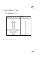
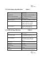
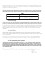
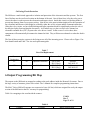
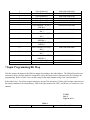
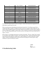
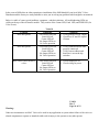
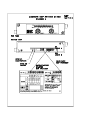
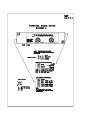
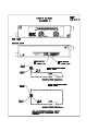
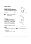
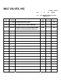
MAC VALVES, INC.
DOCUMENT NUMBER
PAGE
TITLE:
CHANGE
1
OF
19
UI-024
User’s Manual for MAC Valves RIO
SM8 Manifold
REVISION
LEVEL
DATE
RELEASED
A
11-15-99
ENGINEERING RELEASE
16166
TRJ
B
12-13-99
DIP SWITCH SETTINGS CHANGED
16241
TRJ
C
4-6-00
FIGURE 2 UPDATED TO INCLUDE MINI POWER
16523
TRJ
CONNECTOR AND MICRO BUS CONNECTOR
ECN
NUMBER
P.E.
APPROVAL
P.D.
APPROVAL
UI-024
Rev C
Page 2 of 19
User's Manual
for
MAC Valves
Allen-Bradley RIO
SM8 Serial Manifold
12/13/99
1. SYSTEM OVERVIEW
1-1 Remote I/O
The Remote I/O System is an Allen-Bradley proprietary control system which supports high speed transfer of
control information. A typical network consists of one master PLC and multiple slave devices. Allen-Bradley
does not warrant or support this product. All warranty and support services for this product are the
responsibility of and provide by MAC Valves Inc.
The master (PLC with its network scanner) and slave devices are connected via a standard Belden cable which
provides communications to the product.
The scanner communicates with each slave device on the network in an exchange referred to as data exchange.
Data transferred on the network is organized by node addresses. These addresses are grouped by rack number
and starting quarter. There can be up to 16 slaves on the primary racks (numbers 0-3). Each slave device is
assigned a node number (or address) so it can communicate with the network.
The introduction of a new product on the network varies slightly from master to master but in general, the
process is as follows:
1. Set the address dip switches on the slave to correspond to the required node number. This includes the rack
number and starting quarter.
2. Set the baud rate dip switches to correspond to network baud rate.
3. Wire the communications bus on the new product.
4. Place power on the new node (product).
5. Initialize the master.
6. Ensure the “G” file in the master is set for the new node number.
7. Program the master for the required work.
8. Go online.
UI-024
Rev C
Page 3 of 19
1-2 MAC Valves SM8 Serial Manifold
The MAC Serial Manifold (SM8) is a slave device within the Allen-Bradley Remote I/O network. Thus, it will
respond to all of the commands associated with the network like any other node of its type. The PLC
programmer will not have to make any special allowances with this product.
Since the MAC SM8 Unit is nothing more than a node on the Remote I/O network, it can also be used in
conjunction with our Serial Input Manifold (SIM), SLIM, or any other RIO compatible device.
Each SM8 occupies a single node in the network. The output and input portion occupy 1/4 rack. Thus, 16
output bits are controlled and 16 input bits are monitored. We can thus control up to 16 MAC solenoid valves
and read (with the tethered input module) up to 16 user supplied sensors. We will discuss the inputs later in this
document. The memory location and addressing of these bytes also will be discussed later in this document.
Along with 16 output channels, the SM8 has the capability to read 16 input channels. These inputs are
interfaced to either up to four inputs on top of the electronics box or up to 16 inputs for the tethered input
module. The inputs which are accepted by our electronics can be either NPN or PNP type. This must be known
prior to powering the unit up. If the inputs are improperly wired, damage can occur to the switches.
Each SM8 is mounted directly to the MAC Valve manifold and is connected to the PLC network via the a three
pin phoenix style terminal connector rather than individual wires for each solenoid and each input as would be
the case for discretely wired manifolds. This greatly reduces both the amount of wiring and the time required to
get the product on line compared to conventionally wired system.
MAC Valve SM8s have pre-wired solenoid connections. It is only necessary to make the communication and
power connections to the Serial Interface terminals and to set the node address and baud rate dip switches,
located on the bottom of the electronics box, at the time of installation. The MAC SM8 system comes with a
standard five phoenix style connector for electronics and valve power. Thus, the amount of wiring by way of the
connectors is minimized.
UI-024
Rev C
Page 4 of 19
2. SYSTEM STRUCTURE
2.1 Applicable PLCs
Table 1
Allen-Bradley PLC/Processor Type
Max. # SI Units
SLC-500 (5/02 w/RIO Scanner 174716
SN)
PLC-5/11
4
PLC-5/15
12
PLC-5/VME
4
PLC-5/20
12
PLC-5/25
16
PLC-5/40
60
PLC-5/40L
30
PLC-5/60
64
PLC-5/60L
32
PLC-5/250 (5250-LP1, 5250-LP2)
128
PLC-3/10 (1775-LP4, 1775-LP8, 175128
LPA, 1775-LPD)
PLC-3 (1775-L3)
128
PLC-2/20
32
PLC-2/30
32
Consult the factory for other applications.
UI-024
Rev C
Page 5 of 19
2.2 Applicable MAC Valve Series for the SM8 Unit
The following are the valves which can be used with the SM8:
34/44 Series
35/45 Series
37/47 Series
ISO1/2/3 Series
82 Series
92 Series
6200 Series
6300 Series
6500 Series
6600 Series
Please consult the factory for other series to be made available and additional options.
3. SPECIFICATIONS
3-1 General Specifications
Table 2
Item
Specifications
Operating ambient temperature
0~+50°C
Operating ambient humidity
10~90% RH (no condensation)
Vibrating resistance
5G (10~55 Hz, 0.5mm)
Impact resistance
10G
Dielectric strength
500VAC 60 Hz for 1 sec.
(between external terminal and case)
Insulation resistance
10Mohm
Operating atmosphere
No corrosive gases
UI-024
Rev C
Page 6 of 19
3-2 Performance Specifications
Table 3
Item
Specification
Applicable PLC
Allen-Bradley Co. (Refer to Table 1)
Remote I/O Processor/Scanner
1771 RIO (Refer to Table 1)
Max. # of SI Units per Master Station
(Refer to Table 1)
Transmission Speed
Transmission Distance
57.6 kbaud/ 115.2 kbaud/ 230.4 kbaud
Transmission Path
10,000ft (3000m) @57.6kbaud
5,000ft (1500m) @115.2kbaud
2,500ft (750m) @230.4kbaud
Shielded Twisted Pair Cable
Belden type 9463 (Blue Hose)
3-3 SM8 Unit Specifications
Table 4
Item
Specification
Power supply voltage
For solenoid valves 24VDC +/-10%
For SM8 Unit (internal) 24VDC +/-10%
Power consumption
For solenoid valves: Max. 4.0A
For SI Unit (internal) and Inputs:
Max. 1A
Output points
16 points 5.4W/Channel Max (24VDC)
Input points
16 points
Residual voltage
1.0 V or less
Weight
0.75kg
Dimensions
34x71x146mm (Without Connectors)
UI-024
Rev C
Page 7 of 19
4 SWITCH SETTINGS
4-1 Addressing
(DIP SW1 - Refer to Fig. 1)
The Allen-Bradley Remote I/O system of addressing uses “logical racks” and “starting quarter” as a bases for
the node address. The basic system uses four racks with four quarters in these racks for a maximum of sixteen
node addresses possible. Since each SM8 must have a unique address, with the basic system, there are sixteen
available addresses for the SM8 unit. There are methods to increase the number of logical racks inside the
system. Please consult Allen-Bradley for the methods which are applicable for each specific PLC.
Inside each controller is a file called a “G” file. It contains three words of 16 bits each which set the address
(and
ultimately) which output and input words are allocated to which SM8. For example, the G file words (for the
basic system) for a particular system could look something like this:
G0
G1
G2
RIO
Rack 3
Start Gr.
6420
0010
0100
0100
RIO
Rack 2
Start Gr.
6420
0001
0001
0001
RIO
Rack 1
Start Gr.
6420
0000
0010
0010
RIO
Rack 0
Start Gr.
6420
1100
1000
1000
In this example, we have four SM8 units addressed. Note the user only sets words G1 and G2. The word
labeled “G0” is assigned by the computer and should not be modified.
The first word the user has to set to address the SM8 is G1. This is called the Device Address. For our
example, we have four devices assigned. The other word is called the Device Size. Since all of the SM8 units
occupy ¼ of a rack, they all need one bit of G2.
In our example the left four bits of G1 are 0100. This means for RIO Rack 3 we want an SM8 in Starting Group
4. Starting Group 4 controls output words O:x.28 and O:x.29 along with input words I:x.28 and I:x.29. In order
to complete the addressing of this SM8 unit, we must set word G2 bit 14 (least significant bit is far right , most
significant bit is left) to 1 so that the left nibble is 0100. This is translated to mean we are starting on Group 4
and the third 1/4 rack in size.
The next SM8 uses the third nibble in both G1 and G2. This time we want to operate output words O:x.16 and
O:x.17 along with input words I:x.16 and I:x.17. In order for us to do this, we assign the second nibble of G1 to
read RIO Rack 2, Starting Group 0 or 0001 and assign the third nibble of G2 to read first Starting Quarter or
0001.
UI-024
Rev C
Page 8 of 19
The third SM8 uses output words O:x.10 and O:x.11 and input words I:x.10 and I:x.11. Our assignment for G1
is 0010, which means RIO Rack 1, Starting Group 2. Our G2 (second nibble) would be 0010 or second Starting
Quarter.
The last SM8 unit will control words O:x.6, O:x.7, I:x.6, and I:x.7. In order to get this combination, we set the
first nibble of G1 to 1000 or as it reads, RIO Rack 0, Starting Group 6. G2 becomes 1000 or the fourth Starting
Quarter.
The next step in addressing is to set the Starting Quarter and Rack Address dip switches on each SM8 unit.
With the power supply OFF, remove the head from the valve stack. On the bottom, find the 8 bit dip switches.
Use a small anti-static screwdriver to set the positions of the 8 bit switch for the unit's rack position and starting
quarter.
(1) Address (Bits 3-8)
The rack address setting establishes the SI Unit’s “identity” within the RIO network. The setting range is 00-74
Octal (61 different settings). Refer to the appropriate Allen-Bradley manual for the series of PLCs where octal
is used for address identification.
Example of octal, binary, decimal conversion for addressing:
Address 73Oct =59Dec
=32 + 16 + 8 + 2 + 1Binary Places
=Switches 8,7,6,4, and 3 OFF
Address 14Oct=12Dec
=8+4Binary Places
=Switches 6 and 5 OFF
(2) Starting Quarter (Bits 1,2)
The starting quarter setting establishes the group number for a quarter rack device within a full rack address.
There are four possible settings. Note the first starting quarter uses address 00Bin and the fourth starting quarter
uses address 11Bin
UI-024
Rev C
Page 9 of 19
(3) SM8 Dip Switch
From our example above and referring to Figure 1, the SM8 unit which is to be located in RIO
Rack 3, third Starting Quarter should have the Address and Starting Quarter dip switches set as 0000 1110. The
next unit (RIO Rack 2, first Starting Quarter) should be 0000 1000. The unit located at RIO Rack 1, second
Starting Quarter should be 0000 0101. The last unit located at RIO Rack 0, fourth Starting Quarter should be
0000 0011.
4-2 Data Rate (Baud), Clear/Hold Mode, Last Rack
(DIP SW2 - Refer to Fig. 2)
These three functions are set by way of the four bit switch located directly to the right of the eight bit switch.
It is important to note that all of the units on a particular network must operate at the same baud rate. Thus, the
speed which is set into the Scanner Card must be duplicated by all of the nodes on the net or a bus error will
occur.
With the power supply OFF, use a small anti-static screwdriver to set the positions of the four bit switch located
on the bottom plate of the unit to set the data rate, mode, and last rack indications.
(1) Data/Baud Rate (Bits 3,4)
Switch Position
11
10
01
00
Data Rate
57.6kbps
115.2kps
230.4kps
not used
Table 5
Max. I/O Transmission Distance
10,000ft (3000m)
5,000ft (1500m)
2,500ft (750m)
-------
(2) Clear/Hold Mode (Bit 2)
UI-024
Rev C
Page 10 of 19
Switch Position
1 (Clear)
0 (Hold)
Mode of Operation
With the switch in this position, if a
communication error occurs, the Remote
I/O unit clears the current outputs state
and stops operation temporarily. When
the signal becomes normal, the Remote
I/O unit automatically returns to normal
operation.
With the switch in this position, if a
communication error occurs, the Remote
I/O unit holds the last normal signal of the
output and stops operation. When the
signal becomes normal, the Remote I/O
unit must be power cycled due to the
hazards associated with potentially
energized valves.
5 Wiring/Installation
All Wiring and installation steps should be performed with the system power supply off.
5-1 Terminal Blocks
Refer to Figure 2 for terminal identification during installation.
There are two sets of terminal blocks visible on the sides of the unit. The three contact terminal block, located
on the far right is for the communications cable. The five contact terminal block for DC power.
5-2 Wiring of Twisted Pair Cable
The connection of the cable should be as shown in Figure 2. Refer also to the appropriate Allen-Bradley
manual.
Remove the female portion of the three contact terminal block its mate. Cut back the insulation exposing the
wires from the “Blue Hose”cable. There will be a clear inner wire, blue wire, and overall shield. Place the clear
wire with the appropriate resistor (based on the operating baud rate) on the left terminal of the connector and
secure with the screw on the top of the block. Next place the shield in the center conductor and tighten the set
screw. Lastly, place the blue colored wire and the other end of the terminating resistor on the right contact and
tighten the set screw for that terminal. Ensure the wires are fully engaged and not shorting to each other or the
printed circuit board. It is advisable to insulate the shield to prevent shorting.
UI-024
Rev C
Page 11 of 19
Connect terminating resistors at the end of each link. Termination kits are normally included with your AllenBradley Scanner. The type of resistor used is dependent on the baud rate. Use 150 Ohms for 57.6kbaud and
115.2kbaud and 82 Ohms for 230.4kbaud.
There is no restriction as to the spacing between each device or Serial Interface Unit, as long as the maximum
cable distance is not exceeded. However, no two devices may connect to the same point on the RIO network.
Table 6
Type of Cable
Recommended Cable
Shielded, twisted pair (2-core)
Allen-Bradley no. 1771-CD (Blue Hose)
Belden Co., type 9463
5-3 DC Power Wiring
All DC power for the valves, and serial interface is connected through the five contact connector on the side of
the SM8. The first thing that must be decided is the number of power supplies which are to be used to operate
the unit. The system is set up so that a separate DC supply can be used for Inputs/Serial Interfaceand Outputs so
as to be able to lock out a section (i.e. valve power) without turning off the communications section. It is also
possible to operate the entire system from a single DC source. In either case, refer to Figure 2 for terminal
instructions.
5-4 Input/SI Wiring
The MAC SM8 employs the industry standard Eurostyle micro four pin female connector for the modules.
There are many companies which have lines of pre-assembled wire harnesses which will connect the electronics
to a variety of sensors.
Also note the type of switch logic must be know prior to turning the circuit on. The type (NPN or PNP) is
selected by way of a jumper next to the dip switches. Refer to Figure 3 for wiring and jumper information.
5-5 PPC (Proportional Pressure Controllers)
The SM8, using special MODs, can operate up to two PPC5Cs. This is performed by using 4 outputs and 1
input channel per PPC for pressure control. This is then divided so that you can have 16 steps (for 4 bits) of
pressure from lowest to highest and a pressure achieved input (LMS) to control the PPC. Note, because these
pressure controllers consume inputs and outputs, the channels that are used for PPCs can not be used for other
valve control on the stack.
When programming for a PPC, consult the output and input memory mapping table later in this document.
UI-024
Rev C
Page 12 of 19
5-6 Fusing/Circuit Protection
The SM8 uses a multi-tiered approach to isolation and protection of the electronics and bus systems. The first
line of defense are the two fuses location on the bottom of the unit. One of these fuses is for the valve power
circuit, the other is used to protect the electronics and inputs circuit. Inside this circuit is a blocking diode to
prevent any damage from reverse power wiring. Next in line is the opto-isolation imployed for the separation of
any electronic interference which might be created by either the valves or input and the communications bus.
Along the valve circuits, we have both blocking and spike separation diodes to significantly reduce the valve’s
de-energized spike from reaching the electronics. As a farther step, we place on each valve channel, an
electronic resettable fuse (PTC) to protect the valve driver circuits. In the event of a valve short, these
components will automatically disconnect the channel at fault. They will then reset themselves when the fault is
cleared.
The first of these protective systems is the fusing across all of the incoming power. Please refer to Figure 1 for
fuse identification and Table 7 for size and replacement guide.
Table 7
Fuse Size/Replacement
Fuse
Designation
F1
Value
Protects
Connector Ref.
Replace P/N
2A
Input/SI Electronics
F2
4A
Valve Power
PIN 4 (Pos)
PIN 3 (Neg)
PIN 2 (Pos)
PIN 1 (Neg)
Schurter
3405.0921.25
Schurter
3405.0924.25
6 Output Programming/Bit Map
The outputs to the SM8 unit are mapped according to the node address inside the Remote I/O scanner. Due to
the large variety of scanners, please refer to their User’s Manual for complete programming instructions.
The MAC Valves SM8 will consume two consecutive bytes (16 bits) which are assigned for use by the output
section of the SM8 unit to the PLC memory for programming.
Table 8 is a mapping to the word inside the scanner..
UI-024
Rev C
Page 13 of 19
Channel
Table 8
Location
Binary Output Word
1
2
3
4
5
6
7
8
9
10
11
12
13
14
15
16
Valve Solenoid 1
Valve Solenoid 2
Valve Solenoid 3
Valve Solenoid 4
Valve Solenoid 5
Valve Solenoid 6
Valve Solenoid 7 or PPC2
LSB Bit 1
Valve Solenoid 8 or PPC2
Bit 2
Valve Solenoid 9 or PPC2
Bit 3
Valve Solenoid 10 or PPC2
MSB Bit 4
Valve Solenoid 11 or PPC1
LSB Bit 1
Valve Solenoid 12 or PPC1
Bit 2
Valve Solenoid 13 or PPC1
Bit 3
Valve Solenoid 14 or PPC1
MSB Bit 4
Valve Solenoid 15
Valve Solenoid 16
0000 0000 0000 0001
0000 0000 0000 0010
0000 0000 0000 0100
0000 0000 0000 1000
0000 0000 0001 0000
0000 0000 0010 0000
0000 0000 01000 0000
0000 0000 1000 0000
0000 0001 0000 0000
0000 0010 0000 0000
0000 0100 0000 0000
0000 1000 0000 0000
0001 0000 0000 0000
0010 0000 0000 0000
0100 0000 0000 0000
1000 0000 0000 0000
7 Input Programming/Bit Map
Like the outputs, the inputs to the SM8 are mapped according to the node address. The SM8 will produce two
consecutive bytes (16 bits) which are assigned for use by the input section of the unit to the PLC memory for
programming. Refer to Table 9 for a memory map for the input channels using Class 8 and Attribute 3.
In the table below, Top refers to input connectors on top of the electronics, Tether refers to input connectors on
the tethered module (to be released later), LMS is the logic monitor for a PPC, and Water is a watersaver valve
channel.
UI-019
Rev C
Page 14 of 19
Channel
Table 9
Location
Input Binary Word
1
2
3
4
5
6
7
8
9
10
11
12
13
14
15
16
Top 1 or Tether 1
Top 2 or Tether 2
Top 3 or Tether 3 or Water 2
Top 4 or Tether 4 or Water 1
Tether 5
Tether 6
Tether 7
Tether 8
LMS1 or Tether 9
LMS2 or Tether 10
Tether 11
Tether 12
Tether 13
Tether 14
Tether 15
Tether 16
0000 0000 0000 0001
0000 0000 0000 0010
0000 0000 0000 0100
0000 0000 0000 1000
0000 0000 0001 0000
0000 0000 0010 0000
0000 0000 0100 0000
0000 0000 1000 0000
0000 0001 0000 0000
0000 0010 0000 0000
00000 0100 0000 0000
0000 1000 0000 0000
0001 0000 0000 0000
0010 0000 0000 0000
0100 0000 0000 0000
1000 0000 0000 0000
The location of the Input Connectors can be see in Figure 3. Notice each connector has assignments for one
input channel as noted in the above table.
There are two basic types of inputs based on the direction of current flow. We call the two types Positive
Common and Negative Common. The Inputs are factory set by way of a jumper to either of these type. One
word of caution, by setting the jumper for the mode of operation for the module, the whole module is that type
(Positive Common, PNP or Negative Common, NPN). There is no option for connector by connector setting of
type. If the tethered input module option is used, then each row of four inputs can be selected either Postive or
Negative Common.
Refer to Figure 3 in selecting the desired mode of operation for the inputs. The terms “sinking” and “sourcing”
are not used due to the possibility of confusion. In our terminology, Positive Common is used when the load is
connected between the signal pins 2 and the positive voltage terminal pin 1 (typical for PNP logic switches).
Negative Common is used when the load is connected between the signal pins 2 and the negative voltage
terminal pin 3 (typical for NPN logic switches).
UI-024
Rev C
Page 15 of 19
8 Troubleshooting Guide
In the event of difficulties in either operation or installation of the SM8 Manifold, your local MAC Valves
Distributor and the factory are ready and able to assist you in solving any problems which might be encountered.
Below is a table of some typical problems, symptoms, and their solutions. All troubleshooting LEDs are
visible on the top of the electronics module. They consist of the Comm LED, Fault LED, and PWR LED (for
Valve Power).
Problem
Does not operate
Does not operate
RIO is active/does not drive
valves
Table 10
Symptoms
Valve Power LED off
Fault LED off
Comm LED off
No Output LEDs on
No Valve operation
Valve Power LED on
Fault LED on
Comm LED off
No Output LEDs on
No Valve Operation
Valve Power LED off
Fault LED off
Comm LED on
No Output LEDs on
No Valve Operation
Solutions
1. Verify primary 24VDC supply
2. Check fuse F1 and F2/ replace
if blown
1. Verify communications cable
properly connected
2. Verify correct address and
baud rate is set on the dip
switches
1. Check Output fuse F2
2. Check wiring for power
UI-024
Rev C
Page 16 of 19
Warning:
Under no circumstances are MAC Valves to be used in any application or system where failure of the valves or
related components to operate as intended could result in injury to the operator or any other person.
Do not operate outside of prescribed pressure or temperature ranges.
Air supply must be clean. Contamination of valve can affect proper operation.
Before attempting to perform any service on valve, consult catalog, P & O sheet, or factory for proper
maintenance procedures. Never attempt service with air pressure to valve.
If air line lubrication is used, consult catalog, P & O sheet, or factory for recommended lubricants.
Before interfacing the product to any bus or serial system, consult the controller and bus manuals for proper
usage.