1
IB IL TEMP 4/8 RTD ...
Inline analog input terminal,
8 channels, RTDs,
2 and 3-wire connection method
4 x
AUTOMATION
Data sheet
7079_en_05
1
© PHOENIX CONTACT 2011-03-17
Function description
The terminal is designed for use within an Inline station. This
terminal provides an 8-channel input module for resistance
temperature detectors (RTDs).
There are two options for data exchange:
– Via process data (four inputs each in one bus cycle,
multiplex mode)
– Via PCP (all eight inputs in the "Analog Values" PCP
object)
This terminal supports:
– Platinum and nickel sensors, e.g., Pt100, Pt1000,
Ni1000 according to standard DIN EN 60751 and the
SAMA guideline, as well as various other sensors
– KTY81 and KTY84 sensors
– The sensor type Pt10000 especially for building automation
Features
–
–
–
–
–
–
–
Eight inputs for resistive temperature sensors and linear
resistors up to 20 kΩ.
Connection of sensors in 2 and 3-wire technology
Communication via either process data or parameter
channel (PCP)
Channels are configured independently of one another
using the bus system.
Robust inputs, ideal for the use in harsh industrial environments with high electromagnetic interference
Diagnostic indicators
Temperature and resistance measurement in the range
of milliseconds
The measuring temperature is represented by standardized
16-bit values.
This data sheet is only valid in association with the IL SYS INST UM E user manual.
Make sure you always use the latest documentation.
It can be downloaded at www.phoenixcontact.net/catalog.
Function blocks are available to aid use of this terminal.
They can be downloaded at www.phoenixcontact.net/catalog.
This data sheet is valid for all products listed on the following page:
IB IL TEMP 4/8 RTD ...
Table of contents
1
Function description ................................................................................................................... 1
2
Ordering data.............................................................................................................................. 3
3
Technical data ............................................................................................................................ 4
4
Internal basic circuit diagram ...................................................................................................... 7
5
Local diagnostic and status indicators and terminal point assignment........................................ 8
6
Safety note.................................................................................................................................. 9
7
Installation instructions ............................................................................................................... 9
8
Electrical isolation ....................................................................................................................... 9
9
Connection notes........................................................................................................................ 9
10 Connection example................................................................................................................... 9
11 Programming data/configuration data........................................................................................10
12 Process data..............................................................................................................................10
13 OUT process data words ...........................................................................................................10
14 IN process data words ...............................................................................................................13
15 Formats for representing measured values................................................................................15
16 PCP communication ..................................................................................................................18
17 Configuration and analog values................................................................................................21
18 Measuring ranges ................................................................................................................................................ 22
19 Measuring errors........................................................................................................................23
20 General notes and recommendations for the signal/noise ratio .................................................25
21 Step response ...........................................................................................................................26
7079_en_05
PHOENIX CONTACT
2
IB IL TEMP 4/8 RTD ...
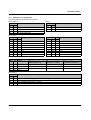
2
Ordering data
Terminal blocks
Description
Type
Order No.
Pcs. / Pkt.
Inline analog input terminal,
complete with accessories (connectors and labeling fields),
8 channels, RTDs, 2 and 3-wire connection method,
transmission speed of 500 kbps,
terminal points of connectors numbered individually
IB IL TEMP 4/8 RTD-PAC
2863915
1
Inline analog input terminal,
complete with accessories (connectors and labeling fields),
8 channels, RTDs, 2 and 3-wire connection method,
transmission speed of 500 kbps,
terminal points of connectors numbered continuously
IB IL TEMP 4/8 RTD-PAC/CN
2692487
1
Inline analog input terminal,
complete with accessories (connectors and labeling fields),
8 channels, RTDs, 2 and 3-wire connection method,
transmission speed of 2 Mbps,
terminal points of connectors numbered individually
IB IL TEMP 4/8 RTD-2MBD-PAC
2878612
1
Inline analog input terminal, without accessories,
8 channels, RTDs, 2 and 3-wire connection method,
transmission speed of 500 kbps
IB IL TEMP 4/8 RTD
2863009
1
Inline analog input terminal, without accessories,
8 channels, RTDs, 2 and 3-wire connection method,
transmission speed of 2 Mbps
IB IL TEMP 4/8 RTD-2MBD
2862916
1
You need 4 connectors with shield connector for the IB IL TEMP 4/8 RTD and IB IL TEMP 4/8 RTD-2MBD terminals.
Accessories
Description
Type
Order No.
Pcs. / Pkt.
Connector with shield connection
IB IL SCN-6 SHIELD-TWIN
2740245
5
Shield connection clamp for applying the shield on busbars, 8 mm diameter
SK8
3025163
10
Shield connection clamp for applying the shield on busbars, 14 mm diameter
SK14
3025176
10
Shield connection clamp for applying the shield on busbars, 20 mm diameter
SK20
3025189
10
Shield connection clamp for applying the shield on busbars, 35 mm diameter
SK35
3026463
10
Support for assembly on DIN rails
for 10 mm x 3 mm busbars
AB-SK
3025341
10
Support for direct mounting with contact to the mounting surface
AB-SK 65
3026489
10
Support, made of insulation material, with fixing screws, can be used for either
10 mm x 3 mm or 6 mm x 6 mm busbars
AB-SK/E
3026476
10
N busbar, 10 mm x 3 mm, 1 m long
NLS-CU 3/10
0402174
1
End terminal, 4 mm2 , without insulating cap
AK 4
0404017
50
End terminal, 4 mm2 , with insulating cap,
green-yellow for PE
AK G GNYE
0421029
50
End terminal, 4 mm2 , with insulating cap,
black for L1, L2, L3
AKG 4 BK
0421032
50
Documentation
Description
Type
Order No.
Pcs. / Pkt.
"Automation terminals of the Inline product range" user manual
IL SYS INST UM E
–
–
"Peripherals Communication Protocol (PCP)" user manual
IBS SYS PCP G4 UM E
2745169
1
"Porting using PCP compact" user manual
IBS PCP COMPACT UM E
9015349
1
7079_en_05
PHOENIX CONTACT
3
IB IL TEMP 4/8 RTD ...
3
Technical data
General data
Housing dimensions (width x height x depth)
48.8 mm x 136.8 mm x 71.5 mm (with connectors)
Weight
125 g (without connectors), 190 g (with connectors)
Operating mode
Process data mode with 5 words/1 word PCP
Connection method for sensors
2 and 3-wire technology
Ambient temperature (operation)
-25°C ... +55°C
Ambient temperature (storage/transport)
-25°C ... +85°C
Permissible humidity (operation/storage/transport)
10% ... 95%, according to DIN EN 61131-2
Permissible air pressure (operation/storage/transport)
70 kPa ... 106 kPa (up to 3000 m above sea level)
Degree of protection
IP20
Class of protection
Class III, EN 61131-2, IEC 61131-2
Connection data for Inline connectors
Connection method
Spring-cage terminal blocks
Conductor cross section
0.08 mm2 ... 1.5 mm2 (solid or stranded), 28 - 16 AWG
Interface
Inline local bus
Inline data routing
Transmission speed
IB IL TEMP 4/8 RTD,
IB IL TEMP 4/8 RTD-PAC,
IB IL TEMP 4/8 RTD-PAC/CN
500 kbps
IB IL TEMP 4/8 RTD-2MBD,
IB IL TEMP 4/8 RTD-2MBD-PAC
2 Mbps
Power consumption
500 kbps
2 Mbps
Communications power UL
7.5 V
7.5 V
Current consumption from UL
75 mA (typical)
100 mA (typical)
I/O supply voltage UANA
24 V DC
24 V DC
Current consumption at UANA
28 mA (typical)
41 mA (typical)
Total power consumption
1.24 W (typical)
1.75 W (typical)
Supply of the module electronics and I/O through bus coupler/power terminal
Connection method
Potential routing
Analog inputs
Number
8 analog RTD inputs
Description of the input
Input for resistive temperature sensors
Connection method
Spring-cage connection
Connection method
2, 3-wire (shielded)
Linear resistance range
0 Ω ... 400 Ω, 0 Ω ... 20 kΩ
Sensor types that can be used
Pt, Ni, KTY, Cu, linear resistors
Standards for characteristic curves
According to DIN EN 60751: 07/1996/
according to SAMA RC 21-4-1966
Measuring principle
Successive approximation
Measured value representation
16 bits (15 bits + sign bit)
Conversion time of the A/D converter
5 µs, typical; 10 µs, maximum
Process data update
6 ms (up to 230 ms possible depending on the connection method)
Data formats
IB IL, IB ST, S7-compatible
Accuracy
0.06% (typical), 0.25% (maximum)
Accuracy
±0.5°C (typical)
7079_en_05
PHOENIX CONTACT
4
IB IL TEMP 4/8 RTD ...
Additional tolerances influenced by electromagnetic fields
Type of electromagnetic interference
Typical deviation of the measuring range final value
Relative for the input area
linear R 0 to 400 Ω
Relative for the input area
linear R 0 to 20 kΩ
Electromagnetic fields;
field strength 10 V/m
according to EN 61000-4-3/IEC 61000-4-3
< ±4.8%
< ±0.5%
Conducted interference
Class 3 (test voltage 10 V)
according to EN 61000-4-6/IEC 61000-4-6
< ±3.5%
< ±0.3%
Tolerances at TA = +25°C
Sensor type
Range
Lower limit
Upper limit
TA = +25°C
Absolute deviation
Typical
Maximum
TA = +25°C
Relative deviation
Typical
Maximum
Pt100DIN and SAMA
(3-wire connection)
-200°C
+850°C
±0.50°C
±2.13°C
±0.06%
±0.25%
Pt100DIN and SAMA
(2-wire connection)
-200°C
+850°C
±1.22°C
±5.64°C
±0.14%
±0.66%
Pt10000 DIN and SAMA
(2 and 3-wire connection)
0°C
+70°C
±0.60°C
±1.80°C
±0.86%
±2.57%
Pt10000 DIN and SAMA
(2 and 3-wire connection)
-200°C
+180°C
±1.24°C
±3.10°C
±0.69%
±1.72%
Rlin400
(3-wire termination)
0Ω
400 Ω
±0.20 Ω
±0.83 Ω
±0.05%
±0.21%
Rlin400
(2-wire termination)
0Ω
400 Ω
±0.48 Ω
±2.20 Ω
±0.12%
±0.55%
Rlin20k
(2 and 3-wire termination)
0Ω
20000 Ω
±150 Ω
±200 Ω
±0.75%
±1.00%
The data contains the offset error, gain error, and linearity error in its respective basic setting. The data is related to nominal operation (preferred mounting position, US = 24 V) with pre-set 32-sample filter. Please also observe the
values for temperature drift and the tolerances under EMI.
All errors indicated as a percentage are related to the positive measuring
range final value.
The maximum tolerance values represent the worst case measurement inaccuracy. They contain the theoretically maximum possible tolerances in the
corresponding measuring ranges. In the same way, the theoretical maximum
possible tolerances of the calibration and test equipment have been taken
into account. This data is valid for at least twelve months.
Temperature and drift response
Sensor type
Range
Lower limit
Upper limit
TA = -25°C to +55°C
Drift (related to the measuring range final value)
Typical
Maximum
Pt100 DIN and SAMA
-200°C
+850°C
60 ppm/K
220 ppm/K
Pt1000 DIN and SAMA
-200°C
+850°C
150 ppm/K
500 ppm/K
Pt10000 DIN and SAMA
1200 ppm/K
-200°C
+180°C
390 ppm/K
Rlin400
0Ω
400 Ω
60 ppm/K
250 ppm/K
Rlin20k
0Ω
20000 Ω
280 ppm/K
900 ppm/K
Protective equipment
Short-circuit protection for each input
7079_en_05
Yes
PHOENIX CONTACT
5
IB IL TEMP 4/8 RTD ...
Electrical isolation
Common potentials
The 24 V main voltage UM, 24 V segment voltage US, and GND have the same potential. FE is a separate potential area.
Separate potentials in the IB IL TEMP 4/8 RTD terminal
Test distance
Test voltage
7.5 V supply (bus logic)/
±15 V, ±5 V analog supply (analog I/O)
500 V AC, 50 Hz, 1 min.
7.5 V supply (bus logic)/functional earth ground
500 V AC, 50 Hz, 1 min.
±15 V, ±5 V analog supply (analog I/O)/functional earth ground
500 V AC, 50 Hz, 1 min.
Error messages to the higher-level control or computer system
Failure of the internal I/O voltage supply
Yes, I/O error message sent to the bus coupler
Failure of or insufficient communications power UL
Yes, I/O error message sent to the bus coupler
Error messages via process data
Peripheral fault/user error
Yes (see page 15)
Mechanical requirements
Vibration, IEC 60068-2-6; EN 60068-2-6
5g
Shock, IEC 60068-2-27; EN 60068-2-27
30g
Approvals
For the latest approvals, please visit www.phoenixcontact.net/catalog.
7079_en_05
PHOENIX CONTACT
6
IB IL TEMP 4/8 RTD ...
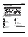
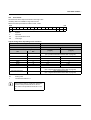
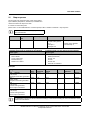
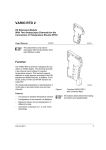
4
Internal basic circuit diagram
L o c a l b u s
U
U
O P C
S R E
1
L +
A N A
U
L -
L e v e ls h ift 3 V /5 V
S u p e r v is o r
2 4 V
± 5 V
± 1 5 V
R E F
µ C
V o lta g e
M o n ito r in g
M U X
IK
+ 2 4 V (U
M
2
IK
3
IK
4
IK
IK
5
6
IK
IK
7
8
)
S
+ 2 4 V (U
IK
1
M U X
)
7 0 7 9 A 0 0 2
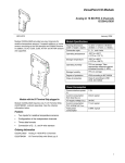
Figure 1
Internal wiring of the terminal points
Key:
Amplifier
OPC
S R E
1
Protocol chip
V o lta g e
M o n ito r in g
Voltage monitoring
Register expansion
x x x
L e v e ls h ift 3 V /5 V
X X X
M U X
S u p e r v is o r
µ C
DC/DC converter with electrical isolation
Level adaptation
Multiplexer
Hardware monitoring
Constant current source
Microcontroller
Optocoupler
Other symbols used are explained in the
IL SYS INST UM E user manual.
Analog/digital converter
R E F
7079_en_05
Reference voltage
PHOENIX CONTACT
7
IB IL TEMP 4/8 RTD ...
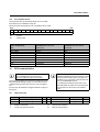
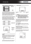
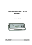
5
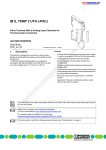
Local diagnostic and status indicators and terminal point assignment
T R
D
T E M P 4 /8 R T D
5.2
Terminal point assignment for 2-wire
connection
Terminal
points
X.1
X.2
Signal
Assignment
I1+/U1+
I1-/U1-
X.3
X.1
X.2
–
I2+/U2+
I2-/U2-
X.3
X.4, 2.4
–
–
RTD sensor 1
I: Constant current supply
U: Measuring input
–
RTD sensor 2
I: Constant current supply
U: Measuring input
–
FE
5.3
1
Terminal
points
X.1
X.2
X.3
X.1
X.2
X.3
X.4, X.4
2
1 .1
1
1
2 .1
1 .2
2
2
2 .2
1 .3
3
3
2 .3
1 .4
4
4
2 .4
Terminal point assignment for 3-wire
connection
Signal
Assignment
I1+/U1+
I1U1I2+/U2+
I2U2–
RTD sensor 1
Constant current supply
Measuring input sensor 1
RTD sensor 2
Constant current supply
Measuring input sensor 2
FE
7 0 6 3 A 0 0 3
Figure 2
IB IL TEMP 4/8 RTD
with an appropriate connector
A
B
4x
1
x
Function identification
1.1
Green
1.2
1
2
x
1
2
2
3
3
2.1
1.1
2.2
1.2
2.3
1.3
2 Mbps: white stripe in the vicinity of the D LED
1.3
5.1
Des.
D
TR
Local diagnostic and status indicators
1.4
4
4
2.4
1
x
1.4
2
1
1.1 2.1
1
11
1.2 2.2
2
4
2
1
2
11
11
22
22
2
33
33
3
3.4 4.4 5.4 6.4 7.4 8.4
44
44
44
Color Meaning
Green Diagnostics
Green PCP active
4
8.1
8.2
8.3
8.4
7079A003
Figure 3
A)
B)
7079_en_05
x
1
3.3 4.3 5.3 6.3 7.3 8.3
33
1.4 2.4
1
3.2 4.2 5.2 6.2 7.2 8.2
22
1.3 2.3
3
2
3.1 4.1 5.1 6.1 7.1 8.1
Terminal point numbering: individual
connectors (A) and connector sets (B)
Using the IB IL TEMP 4/8 RTD-PAC and
IB IL TEMP 4/8 RTD-2MBD-PAC with the connectors provided.
Using IB IL SCN-6 SHIELD-TWIN
individual connectors
Using the IB IL TEMP 4/8 RTD-PAC/CN
terminal with the provided connectors
PHOENIX CONTACT
8
IB IL TEMP 4/8 RTD ...
6
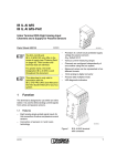
Unused channels
Safety note
During configuration, ensure that no isolating voltage for safe isolation is specified between the analog inputs and the bus. During thermistor
detection, for example, this means that the user
has to provide signals with safe isolation, if applicable.
7
Short-circuit unused channels (see Figure 5 on page 9,
channels 2 to 7).
This ensures that the measuring values at the other channels are within the specified tolerances.
10
Connection example
When connecting the shield before the terminal,
insulate the shield on the sensor side (shown in
gray in Figure 5). Figure 5 shows the connection
schematically.
Installation instructions
High current flowing through potential jumpers UM and US
leads to a temperature rise in the potential jumpers and inside the terminal. To keep the current flowing through the
potential jumpers of the analog terminals as low as possible,
always place the analog terminals after all the other terminals at the end of the main circuit (for the sequence of the Inline terminals, see also IL SYS INST UM E user manual).
8
Connection of passive sensors
Slot
1
Channel
4
3
2
1 2 3 4 5 6 7 8
Electrical isolation
D
TR
L o c a l b u s (IN )
U
L
B u s c o n n e c tio n
O P C
a n d m ic r o c o n tr o lle r
(7 .5 V D C )
U
L
U
U
A N A
(2 4 V D C )
2 4 V
± 5 V
± 1 5 V
Figure 4
(7 .5 V D C )
A N A
1
(2 4 V D C )
A
I/O
in te r fa c e
± 5 V
± 1 5 V
F E p o te n tia l
TEMP 4/8 RTD
L o c a l b u s (O U T )
A n a lo g in p u ts
B
E le c tr ic a l is o la tio n
b e tw e e n a re a
A a n d B
7 0 6 3 A 0 0 5
2
1
2
1
2
1
2
I 1+ 1
11
11
11
1
I 8+
I 1-
2
22
22
22
2
I 8-
3
33
33
33
3
U8-
4
44
44
44
4
Electrical isolation of the individual function
areas
7063B007
9
Connection notes
Figure 5
Connection of sensors in 2 and 3-wire technology with shield connection
Connecting the resistance temperature detectors
Always connect temperature shunts using shielded,
twisted-pair cables.
Channel 1: 2-wire technology; channel 8: 3-wire technology
Other channels: not used (with short-circuit jumpers)
Connecting the shield
The connection examples show how to connect the shield
(Figure 5).
Insulate the shield at the sensor.
7079_en_05
PHOENIX CONTACT
9
IB IL TEMP 4/8 RTD ...
11
Programming data/configuration data
INTERBUS (local bus)
ID code
Length code
Process data channel
Input address area
Output address area
Parameter channel (PCP)
Register length (bus)
12
Other bus systems
DFhex (223dec)
05hex
80 bits
5 words
5 words
1 word
6 words
For the programming data/configuration data of
other bus systems, please refer to the corresponding electronic device data sheet (e.g.,
GSD, EDS).
Process data
The terminal has five process data words and one PCP word.
O U T 1
O U T
IN 1
S ta tu s w o rd
IN
Figure 6
13
O U T 2
O U T 3
O U T 4
O U T 5
IN 2
IN 3
IN 4
IN 5
C o n tro l w o rd
7 0 6 3 A 0 0 8
Order of the process data words
OUT process data words
Five process data output words are available.
Configure the terminal channels via the OUT process data
words OUT1 and OUT2. In this context, the output word
OUT1 contains the command and the output word OUT2
contains the parameters belonging to this command.
The following configurations are possible:
Configuration
Selection of mean-value
generation (filtering)
Type of sensor connection
Short
designation
Filter
Default
If you change the configuration, the message "Measured
value invalid" appears (diagnostic code 8004hex), until new
measured values are available.
Please note that extended diagnostics is only
possible if the IB IL format is configured as the format for representing the measured values. As this
format is preset on the terminal, it is available as
soon as the voltage is applied.
16-sample
mean value
Connec3-wire techtion
nology
Value of reference resistance R0 R0
100 Ω
Resolution setting
Resolution 0.1°C
Selection of the format for repre- Format
IBIL format
senting measured values
Sensor type setting
Sensor
Pt100 (DIN)
type
Configuration errors are indicated in the status word. The
configuration settings are stored in a volatile memory.
7079_en_05
PHOENIX CONTACT
10
IB IL TEMP 4/8 RTD ...
13.1
Output word OUT1 (control word)
OUT1
Bit
15
14
13
12
11
10
9
8
Command code
Assignment
7
6
5
4
3
2
1
0
0
0
0
0
0
0
0
0
1
0
Bit 15 to bit 8 (command code):
0
0
0
0
0
0
Bit 15 to bit 8
0
0
0 C
0
0
1
0
0
0
1
0
C
0
0
OUT1
C 0x00hex
0 0800hex
1 0900hex
0
0
0
0
1
0
1
0
0
0
0
0
0
1
0
1
0
1
1
0
0
1
0
C
1
C
C
0
C
C 1x00hex
0 3C00hex
C 4x00hex
0
1
0
1
0
C
C
C 5x00hex
0
1
1
0
0
0
0
0
0A00hex
6000hex
Command function
Read measured value in IN2 channel-by-channel.
Read measured values of channels 1 to 4 in IN2 to IN5.
Read measured values of channel 5 to 8 into IN2 to IN5.
Read measured values of channels 1 to 4 in IN2 to IN5.
Conversion of these channels only (shorter conversion time)
Read configuration in IN2 channel-by-channel.
Read firmware version and module ID in IN2.
Configure channel, configuration in OUT2
Configure channel and read measured value of the channel,
configuration in OUT2, measured value in IN2.
Configure entire terminal (all channels);
configuration in OUT2.
CCC = channel number
13.2
Output word OUT2 (parameter word)
The parameters for the commands 4x00hex, 5x00hex, and
6000hex must be specified in OUT2. This parameter word is
only evaluated for these commands.
OUT2
Bit
15
Assignment
0
Filter
14
13
Filter
12
2/3
11
10
9
R0
Selects mean value generation. After every
conversion, the measured value is saved in a
mean value memory via which the mean
value is generated. The memory size can be
selected with the filter option. E.g., for a 16sample mean value, the mean value is generated using the last 16 measured values.
2/3
Connection method, 2-wire or 3-wire
Selection of sensor resistance at 0°C.
R0
Here, for example, you can select whether
Pt100, Pt500, Pt1000 or Pt10000 are to be
used for the platinum sensor type.
Resolution Quantization of the measured value, choice
between °Celsius or °Fahrenheit
Format
Represents the measured value in the IN
process data
Sensor type Sets the selected sensor type
7079_en_05
8
7
6
Resolution
5
4
Format
3
2
Sensor type
If invalid parameters are specified in the parameter word, the command will not be executed. The
command is acknowledged in the input words
with the set error bit.
PHOENIX CONTACT
11
IB IL TEMP 4/8 RTD ...
13.3
Parameters for configuration
The values displayed in bold are default settings.
Bit 14 and bit 13:
Code
dec
bin
0
00
1
01
2
10
3
11
Bit 12:
Filter
16-sample mean value
No mean value
4-sample mean value
32-sample mean value
Code
dec
bin
0
0
1
1
Connection method (2/3)
3-wire
2-wire
Code
dec
bin
hex
Bit 11 to bit 8
Code
dec
bin
0
1
2
3
4
5
6
7
0000
0001
0010
0011
0100
0101
0110
0111
R0 [Ω]
hex
0
1
2
3
4
5
6
7
100
10
20
30
50
120
150
200
8
9
10
11
12
13
14
15
1000
1001
1010
1011
1100
1101
1110
1111
R0 [Ω]
8
9
A
B
C
D
E
F
240
300
400
500
1000
1500
2000
10000
Bit 7 and bit 6:
Code
dec
bin
0
1
2
3
00
01
10
11
Resolution for sensor type
0 to 11
13
(Potentiometer [%])
0.1°C
1%
0.01°C
0.1%
0.1°F
Reserved
0.01°F
14
(Linear R: 0 to 400 Ω)
0.1 Ω
0.01 Ω
Reserved
15
(Linear R: 0 to 20000 Ω)
1Ω
0.1 Ω
Reserved
Bit 5 and bit 4
Code
dec
bin
0
00
1
01
2
10
3
11
7079_en_05
Format
IB IL format (15 bits + sign bit with extended diagnostics)
IB ST format (12 bits + sign bit + 3 diagnostic bits)
S7-compatible format (15 bits + sign bit)
Reserved
PHOENIX CONTACT
12
IB IL TEMP 4/8 RTD ...
Bit 3 to bit 0:
Code
dec
bin
0
0000
1
0001
2
0010
3
0011
4
0100
5
0101
6
0110
7
0111
Sensor type
Code
dec
bin
8
1000
9
1001
10 1010
11 1011
12 1100
13 1101
14 1110
15 1111
Pt DIN
Pt SAMA
Ni DIN
Ni SAMA
Cu10
Cu50
Cu53
Ni1000 (Landis & Gyr)
Sensor type
Ni500 (Viessmann)
KTY 81-110
KTY 84
KTY 81-210
Reserved
Potentiometer [%]
Linear R: 0 to 400 Ω
Linear R: 0 to 20000 Ω
Example of a parameterization
Sensor Pt1000 DIN
OUT2
Bit
15
Assignment
0
Assignment
0
14
13
Filter
1
12
11
10
2/3
1
1
14
IN process data words
14.1
Input word IN1 (status word)
9
8
R0
1
1
7
6
Resolution
0
0
5
4
3
Format
2
1
0
Sensor type
0
0
0
0
0
0
0
0
7
6
5
4
3
2
1
0
0
0
0
0
0
0
0
0
The input word IN1 serves as status word.
IN1
Bit
15
Assignment
EB
14
13
12
11
10
Mirrored command code
EB: Error bit
EB = 0
EB = 1
No error has occurred.
An error has occurred.
9
8
Mirroring of the command code:
A command code mirrored from the control word. Here, the
MSB is suppressed.
The following error bits set the error bit during configuration:
– An invalid parameter word was sent.
Remedy: Check the parameters (see "Parameters for
configuration" on page 12)
– Parameterization via process data was disabled during
parameterization via PCP
Remedy: Permit parameterization via process data
("System bit" element, "Conf" bit = 1, see "Config Table
object" on page 19)
7079_en_05
PHOENIX CONTACT
13
IB IL TEMP 4/8 RTD ...
14.2
Input words IN2 to IN5
For the control word 3C00hex, IN2 supplies the firmware
version and the module ID.
The measured values, the configuration or the firmware version are transmitted to the controller board or the PC using
the process data input words IN2 through IN5 in accordance
with the configuration.
Example: firmware version 1.23
IN2
Bit
Assignment
(hex)
Meaning
15
14
13
12
11
10
1
9
MSB
LSB
SB
AV
0
OC
OR
6
5
13
12
11
10
9
8
7
6
13
12
11
10
9
8
7
Analog value
6
3
2
3
1
0
Ehex
Module ID
about the formats, please refer to "Formats for representing
measured values" on page 15.
5
4
3
2
1
LSB
0
IB IL format,
S7-compatible format
Analog value
14
4
Firmware version 1.23
SB
15
SB
7
2
Basically three formats are available for the representation
of the measured values. For more detailed information
MSB
15 14
8
5
4
3
2
0
1
OC
0
OR IB ST format
Most significant bit
Least significant bit
Sign bit
Analog value
Reserved
Open circuit/short circuit
Overrange
Open-circuit detection:
An open circuit is detected according to the following table:
Faulty sensor
cable
I+/U+
IUYes
–
No
7079_en_05
2-wire
3-wire
Yes
Yes
–
Yes
Yes
No
Open circuit is detected.
The cable is not connected when using this
connection method.
Open circuit is not detected.
PHOENIX CONTACT
14
IB IL TEMP 4/8 RTD ...
15
Formats for representing measured values
15.1
IB IL format (default setting)
The measured value is represented in bits 14 to 0. An additional bit (bit 15) is available as a sign bit. This format supports extended diagnostics. Values > 8000hex and
< 8100hex indicate an error.
The following diagnostic codes are possible:
Code
(hex)
8001
8002
8004
8010
8020
8040
8080
Error
Measuring range exceeded (overrange)
Open circuit
Measured value invalid/no valid measured value
available (e.g., because channel was not configured)
Configuration invalid
I/O supply voltage faulty
Terminal faulty
Below measuring range (underrange)
Measured value representation in IB IL format, 15 bits
MSB
15
14
SB
SB
13
12
11
10
9
8
7
6
Analog value
5
4
3
2
1
LSB
0
Sign bit
Typical analog values depending on the resolution
Sensor type
All temperature sensors
Potentiometer
Linear
0 to 400 Ω
Linear
0 to 20 kΩ
Sensor/code
0 to 11
13
14
15
Resolution (bits 7 and 6)
00bin/10bin
00bin
00bin
00bin
Process data item (= analog value)
1%
[%]
0.1 Ω
[Ω]
1Ω
[Ω]
–
–
hex
dec
0.1°C/0.1°F
[°C]/[°F]
8002
–
Open circuit
–
8001
–
Overrange
(see table on page 22)
–
See note below
2710
10000
1000.0
10000 (100 x R0)
0FA0
4000
400.0
4000 (40 x R0)
400.0
000A
10
1.0
10 (0.10 x R0)
1.0
10
0001
1
0.1
1 (0.01 x R0)
0.1
1
0
0
>400.0
>20000
–
10000
4000
0000
0
0
0
FFFF
-1
-0.1
–
–
–
FC18
-1000
-100.0
–
–
–
Underrange
(cf. Table page 22)
–
–
–
8080
7079_en_05
PHOENIX CONTACT
15
IB IL TEMP 4/8 RTD ...
This sensor type (potentiometer) does not have defined upper limits of the measuring range. Depending on the
gain, however, an open circuit is detected at approximately 400 Ω or at approximately 20000 Ω.
Please note for the potentiometer (No. 13) and linear resistor (No. 14 and 15) sensor types that below 0.8% of the
nominal range (e.g., 0 Ω to 3 Ω for the "linear R: 0 to 400 Ω" type) the diagnostic messages "Overrange" and "Underrange" can be generated.
Sensor type
All temperature sensors
Potentiometer
Linear
0 to 400 Ω
Linear
0 to 20 kΩ
Sensor/code
0 to 11
13
14
15
Resolution (bits 7 and 6)
01bin/11bin
01bin
01bin
01bin
Process data item (= analog value)
dec
0.01°C/0.01°F
[°C]/[°F]
0.1%
[%]
0.01 Ω
[Ω]
0.1 Ω
[Ω]
8002
–
Open circuit
–
–
–
8001
–
> 325.12
Overrange
(see page 22)
–
3251.2
325.12
3251.2
2710
10000
100.00
1000.0 (10 x R0)
–
100.00
1000.0
0FA0
4000
40.00
400.0 (4 x R0)
40.00
400.0
000A
10
0.1
1 (0.01 x R0)
0.1
1
0001
1
0.01
0.1 (0.001 x R0)
0.01
0.1
hex
0000
0
0
0
0
0
FFFF
-1
-0.01
–
–
–
FC18 (-1000)
-10
-10
–
–
–
D8F0
-10000
-100.00
–
–
–
Underrange
(see page 22)
–
–
–
8080
If the measured value is outside the representation area of the process data, the "Overrange" or "Underrange" error message is displayed.
Please note for the potentiometer (No. 13) and linear resistor (No. 14 and 15) sensor types that below 0.8% of the
nominal range (e.g., 0 Ω to 3 Ω for the "linear R: 0 to 400 Ω" type) the diagnostic messages "Overrange" and "Underrange" can be generated.
7079_en_05
PHOENIX CONTACT
16
IB IL TEMP 4/8 RTD ...
15.2
IB ST format
The measured value is represented in bits 14 through 3. The
remaining 4 bits are available as sign and error bits.
Measured value representation in IB ST format; 12 bits
MSB
15
14
SB
SB
0
OC
OR
13
12
11
10
9
8
7
Analog value
6
5
4
3
2
0
1
OC
LSB
0
OR
Sign bit
Reserved
Open circuit/short circuit
Overrange
Typical analog values depending on the resolution
Sensor type
Sensor code
Resolution (bits 7 and 6)
Process data item (= analog value)
hex
dec
xxxx xxxx xxxx xxx1bin
2710
03E8
0008
0000
FFF8
FC18
xxxx xxxx xxxx xxx1bin
10000
1000
8
0
-8
-1000
xxxx xxxx xxxx xx1xbin
AV
x
RTD sensor
(0 to 11)
00bin/10bin
0.1°C/0.1°F
[°C]/[°F]
01bin/11bin
0.01°C/0.01°F
[°C]/[°F]
Overrange
(AV = positive final value from the table on page 22)
1000.0
100.00
100.0
10.00
0.8
0.08
0
0
-0.8
-0.08
-100.0
-10.00
Underrange
(AV = negative final value from the table on page 22)
Open circuit/short circuit
(AV = negative final value from the table on page 22)
Analog value
Can have the value 0 or 1
If the measured value is outside the representation area of the process data, bit 0 is set to 1.
In the event of an open/short circuit, bit 1 is set
to 1.
7079_en_05
PHOENIX CONTACT
17
IB IL TEMP 4/8 RTD ...
15.3
S7-compatible format
The measured value is represented in bits 14 to 0. An additional bit (bit 15) is available as a sign bit.
Measured value representation in S7-compatible format; 15 bits
MSB
15
14
SB
SB
AV
13
12
11
10
8
7
6
Analog value
5
4
3
2
1
LSB
0
Sign bit
Analog value
IB input data word
(Two's complement)
(hex)
7FFF
2710 (10000)
03E8 (1000)
0008 (8)
0000
FFF8 (-8)
FC18 (-1000)
8000
16
9
All temperature sensors
Resolution 0.1°C or 0.1°F
(°C) or (°F)
Overrange
1000.0
100.0
0.8
0
-0.8
-100.0
Underrange
All temperature sensors
Resolution 0.01°C or 0.01°F
(°C) or (°F)
Overrange
100.0
10.00
0.08
0
-0.08
-10
Underrange
PCP communication
For information on PCP communication, please
refer to the IBS SYS PCP G4 UM E and
IBS PCP COMPACT UM E user manuals.
By default upon delivery, the terminal is configured according to the default settings on page 10. The terminal can be
configured using process data or PCP to suit your application.
In PCP mode, the terminal is configured with the "Config Table" object.
16.1
The IBS CMD (for standard controller boards)
and IBS PC WORX (for Field Controllers (FC) and
Remote Field Controllers (RFC)) programs are
available for the configuration and parameterization of your INTERBUS system.
For additional information, please refer to the
"IBS CMD SWT G4 UM E" user manual and the
documentation for the version of PC WORX
used.
Object dictionary
Index
0080hex
0081hex
Data type
Array of Unsigned 16
Array of Unsigned 16
A
12
8
L
2
2
Meaning
A:
Number of elements
rd:
Read access permitted
L:
Length of an element in bytes
wr:
Write access permitted
7079_en_05
Object name
Config table
Analog Values
Rights
rd/wr
rd
PHOENIX CONTACT
18
IB IL TEMP 4/8 RTD ...
16.2
Object descriptions
Config Table object
Configure the terminal using this object.
If you configure the terminal using PCP and the "Conf" bit equals 0 in the "System bit" element, parameterization
via process data is disabled.
Set the "Conf" bit to 1 in order to enable parameterization via process data in addition to parameterization via PCP.
Object description:
Object
Config table
Access
Read, Write
Data type
Array of Unsigned 16
Index
0080hex
12 x 2 bytes
Subindex
00hex
01hex
02hex
03hex
04hex
05hex
06hex
07hex
08hex
09hex
0Ahex
0Bhex
0Chex
Write all elements
Configuration of channel 1
Configuration of channel 2
Configuration of channel 3
Configuration of channel 4
Configuration of channel 5
Configuration of channel 6
Configuration of channel 7
Configuration of channel 8
Reserved
System bit
Reserved
Reserved
Length (bytes)
18hex
02hex
Subindex 00hex
Subindex 01hex to 0Chex
Data
Terminal configuration
Element value range
The "Configuration channel x" elements have the following structure:
Bit
15
Assignment
0
14
13
Filter
12
2/3
11
10
9
R0
8
7
6
Resolution
5
4
Format
3
2
1
0
Sensor type
For the value ranges of the individual parameters, please refer to "Parameters for configuration" on page 12.
If an invalid configuration is specified, a negative confirmation is generated with error message 08hex, 00hex or xx30hex. The
low byte of the additional error code is 30hex (value is out of range), the high byte contains the number of the affected element.
Example: Config Table is completely filled with data (subindex 00) and the entry for channel 6 is invalid. In this case, the
additional error code equals 0630hex.
7079_en_05
PHOENIX CONTACT
19
IB IL TEMP 4/8 RTD ...
The "System bit" element is set up as follows:
Bit
15
14
13
12
11
10
9
8
7
6
5
4
3
2
1
0
Assignment
0
0
0
0
0
0
0
0
0
0
0
0
0
0
0
Con
f
"Conf"
If bit 0 = 0, configuration via process data is disabled (default)."Conf"
If bit 0 = 1, configuration via process data is permitted (command codes 40xxhex and 6000hex).
Analog Values object
The elements of this object contain the analog values of the
channels in a format that has been selected for this channel.
Object description:
Object
Analog Values
Access
Read
Data type
Array of Unsigned 16
Index
0081hex
Subindex
00hex
01hex
02hex
03hex
04hex
05hex
06hex
07hex
08hex
Read all elements
Analog value of channel 1
Analog value of channel 2
Analog value of channel 3
Analog value of channel 4
Analog value of channel 5
Analog value of channel 6
Analog value of channel 7
Analog value of channel 8
Length (bytes)
10hex
02hex
Subindex 00hex
Subindex 01hex to 08hex
Data
Analog values of the channels
7079_en_05
8 x 2 bytes
PHOENIX CONTACT
20
IB IL TEMP 4/8 RTD ...
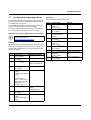
17
Configuration and analog values
The terminal only needs to be configured if the channels are
not to be operated with the default values (see "Parameters
for configuration" on page 12).
You can either configure the terminal via process data or
via PCP and transmit analog values accordingly.
Example 2
Each channel is configured differently.
Step
1
If you have configured the terminal via PCP, the configuration can no longer be modified via the process data.
2
Examples for terminal configuration via process data
3
For easy terminal configuration a function block
can be downloaded at
www.phoenixcontact.net/catalog
4
5
Example 1
All channels are to be configured as Ni1000 in 3-wire technology with 16-sample mean value generation. IBIL is used
as format with a resolution of 0.1°C. The configuration value
is therefore 0002hex.
Step
1
2
3
4
5
6
7
8
Process data
OUT2 = 0C02hex
OUT1 = 6000hex
Wait until
IN1 = 6000hex
OUT1 = 0800hex
6
...
15
Meaning
Specify configuration
16
Wait for confirmation
Process data
OUT2 = configuration for
channel 1
OUT1= 4000hex
Wait until
IN1 = 4000hex
OUT2 = configuration for
channel 2 OUT1 =
4100hex
Wait until
IN1 = 4100hex
OUT2 = configuration for
channel 3
OUT1 = 4200hex
Wait until
IN1 = 4200hex
...
OUT2 = configuration for
channel 8
OUT1= 4700hex
Wait until
IN1 = 4700hex
Meaning
Specify configuration
K1
Wait for confirmation
Specify configuration
C2
Wait for confirmation
Specify configuration
K3
Wait for confirmation
...
Specify configuration
K8
Wait for confirmation
Request the measured
values of channels 1 to
4
Wait for confirmation
Wait until
IN1 = 0800hex
Measured value channel Read measured values
1 = IN2, ...,
Measured value channel
4 = IN5
if
measured value =
80xxhex , an error message is sent, otherwise
temperature in °C =
measured value x 10
Request the measured
OUT1 = 0900hex
values
of channels 5 to 8
Wait until
Wait for confirmation
IN1 = 0900hex
Measured value channel Read measured values
5 = IN2, ...,
Measured value channel
8 = IN5
7079_en_05
PHOENIX CONTACT
21
IB IL TEMP 4/8 RTD ...
18
Measuring ranges
18.1
Measuring ranges depending on the resolution
(IB IL format)
Resolution
00
01
10
11
18.2
Temperature sensors
Temperature values can be converted from °C to
°F with this formula:
T [° F ] = T [° C ] x
-273°C to +3276.8°C; resolution: 0.1°C
-273°C to +327.68°C; resolution: 0.01°C
-459°F to +3276.8°F; resolution: 0.1°F
-459°F to +327.68°F; resolution: 0.01°F
9
5
+ 3 2
Where:
T [°F]
T [°C]
Temperature in °F
Temperature in °C
Input measuring ranges
No.
Input
0
Sensor type
Pt
R0 10 Ω to 2000 Ω
0
Pt10000
1
Pt
R0 10 Ω to 2000 Ω
According to DIN
EN 60751: 07/1996
Measuring range
Lower limit
Upper limit
-200°C
+850°C
-200°C
+180°C
-200°C
+850°C
According to SAMA
1
Pt10000
-200°C
+180°C
2
Ni
R0 10 Ω to 2000 Ω
According to DIN
EN 60751: 07/1996
-60°C
+180°C
Ni
R0 10 Ω to 2000 Ω
According to SAMA
-60°C
+180°C
4
Cu10
According to SAMA
-70°C
+500°C
5
Cu50
According to SAMA
-50°C
+200°C
6
Cu53
According to SAMA
-50°C
+180°C
3
Temperature sensors
7
Ni1000 L&G
-50°C
+160°C
8
Ni500 (Viessmann)
-60°C
+250°C
9
KTY81-110
-55°C
+150°C
10
KTY84
-40°C
+300°C
KTY81-210
-55°C
+150°C
R0 (100%)
11
12
Reserved
13
Relative potentiometer range
0%
14
Linear
resistance
measuring range
0Ω
400 Ω
0Ω
20000 Ω
15
The number (No.) corresponds to the code of the sensor type in bit 3 to bit 0 of the parameter word (see "Sensor
type" on page 13).
Please note for the potentiometer (No. 13) and linear resistor (No. 14 and 15) sensor types that below 0.8% of the
nominal range (e.g., 0 Ω to 3 Ω for the "linear R: 0 to 400 Ω" type) the diagnostic messages "Overrange" and "Underrange" can be generated.
7079_en_05
PHOENIX CONTACT
22
IB IL TEMP 4/8 RTD ...
19
Measuring errors
19.1
Systematic measuring errors during temperature measurement using resistance thermometers
When measuring temperatures using resistance thermometers, systematic measuring errors are often the cause for incorrect measuring results.
T R
The sensors can be connected in 2 or 3-wire technology.
D
T E M P 4 /8 R T D
A
1
IK
R
L
I+
ϑ
R
L
U
M
~ ϑ
2
1
2
1
2
1
B
2
1
1 1
1 1
1 1
1
I+
I2
2 2
2 2
2 2
2
I-
U 3
3 3
3 3
3 3
3
4
4 4
4 4
4 4
4
U
IK
M
R
L
R
L
~ ϑ
7 0 6 3 A 0 0 9
Figure 7
Connecting the resistance thermometers in 3-wire technology (A) and 2-wire technology (B)
With 3-wire technology, the effect of the cable resistance
on the measured result in the terminal is eliminated or minimized by multiple measuring of the temperature-related
voltage and corresponding calculations.
2-wire technology is a more cost-effective connection
method. The U+ and U- cables are no longer needed. The
temperature-related voltage is not directly measured at the
sensor and therefore falsified by the two cable resistances
RL. This connection method is particularly well suited for
sensors with high R0 (e.g., Pt1000, Pt10000, Ni1000).
The measuring errors that occur if R0 is low can make the
entire measurement unusable (see diagrams in Figure 8 to
Figure 10). However, these diagrams show at which points
in the measurement system measures can be taken to minimize these errors.
7079_en_05
PHOENIX CONTACT
23
IB IL TEMP 4/8 RTD ...
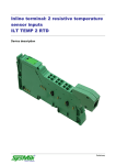
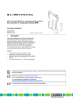
19.2
Systematic errors during temperature measurement using 2-wire technology
1 5 .0
K
1 2 .0
, T
9 .0
(1 )
(2 )
6 .0
(3 )
3 .0
0 .0
0 .0
2 .5
5 .0
7 .5
1 0 .0
1 2 .5
1 5 .0
1 7 .5 m
l
2 0 .0
5 7 5 5 1 0 1 4
Systematic temperature measuring error ΔT
depending on the cable length l
Figure 8
Curves depending on cable cross section A
Temperature measuring error for A = 0.14 mm2
Temperature measuring error for A = 0.25 mm2
Temperature measuring error for A = 0.50 mm2
(1)
(2)
(3)
(Measuring error valid for: copper cable χ = 57 m/Ωmm2,
TA = 25°C and Pt 100 sensor)
6.0
K
5.0
DT 4.0
3.0
2.0
1.0
0.0
A considerable improvement is made through the use of Pt
1000 sensors. Due to the 10 times higher temperature coefficient α (α = 0.385 Ω/K for Pt100 to a = 3.85 Ω/K for Pt1000)
the effect of the cable resistance on the measurement is decreased by a factor of 10. All errors in the diagrams above
would be reduced by factor 10.
Figure 8 clearly shows the effect of the cable length on the
cable resistance and therefore on the measuring error. The
solution is to use the shortest possible sensor cables.
Figure 9 shows the influence of the cable cross-section on
the cable resistance. It can be seen that cables with a cross
section of less than 0.5 mm2 cause errors to increase exponentially.
Figure 10 shows the influence of the ambient temperature
on the cable resistance. This parameter is of minor importance and can hardly be influenced. It is mentioned here
only for the sake of completeness.
The formula for calculating the cable resistance is as follows:
RL =
RL =
RL20 x ( 1 + 0.0039
l
cxA
1
K
x ( 1 + 0.0039
x (TA - 20°C))
1
K
x (TA - 20°C))
Where:
0
0.1
0.2
0.3
0.4
0.5
0.6
0.7
0.8
mm² 1.0
A
70790015
Systematic temperature measuring error ΔT
depending on the cable cross section A
Figure 9
(Measuring error valid for: copper cable χ = 57 m/Ωmm2,
TA = 25°C, l = 5 m,and Pt 100 sensor)
A
0.0039 1/K
TA
2.5
K
2.0
DT
1.5
Cable resistance in Ω
Cable resistance at 20°C in Ω
Cable length in m
Specific electrical conductivity of copper in
Ωmm2/m
Cable cross section in mm2
Temperature coefficient for copper
(degree of purity of 99.9%)
Ambient temperature (cable temperature)
in °C
Since there are two cable resistances in the measuring system (forward and return), the value must be doubled.
1.0
0.5
0.0
-30
RL
RL20
l
χ
-20
-10
0
+10
+20
+30
+40 +50 °C +60
TA
57550016
Figure 10
The absolute measuring error in Kelvin [K] is provided for
platinum sensors according to DIN using the average temperature coefficient α (α = 0.385 Ω/K for Pt100; α = 3.85 Ω/
K for Pt1000).
Systematic temperature measuring error ΔT
depending on the cable temperature TA
(Measuring error valid for: copper cable χ = 57 m/Ωmm2,
l = 5 m, A = 0.25 mm2, and Pt 100 sensor)
All diagrams show that the increase in cable resistance
causes the measuring error.
7079_en_05
PHOENIX CONTACT
24
IB IL TEMP 4/8 RTD ...
20
General notes and recommendations for the signal/noise ratio
Optimizing the signal/noise ratio in RTD applications using
the IB IL TEMP 4/8 RTD terminal.
Background:
The terminal used has a high dynamic performance and can
quickly detect the smallest changes in resistance or temperature. In practice, however,a Pt100 sensor in air immediately passes on even the smallest changes. Temperature
fluctuations due to air circulation are measured immediately
and are transmitted to the higher-level PLC.
Remedy:
High dynamics is not required for all applications. In order to
obtain more stable measured values, set the internal filtering parameter to 32-sample filtering. Moreover, an additional application filter can improve the signal/noise ratio. As
far as noise levels are concerned, 2-wire operation is more
favorable than 3-wire operation.
The thermal system at the sensor can be slowed, if required.
This can be achieved, for example,by installing it on a body
with a high thermal storage capacity. This could be, for example, a metal block of aluminum or steel. The signal/noise
ratio will be influenced positively.
Overview of the recommended measures for temperature measurements with minimized noise:
No.
Sensor type
Filter
1
Pt100
Ni100
32
Connection
2/3
2
Pt1000
Ni1000
Pt10000
32
2
32
2
3
Remarks
Other
With regard to the signal/noise ration it –
is much better to use 2-wire termina- –
tion instead of 3-wire termination for
terminal operation.
Check the tolerances for each respec- –
tive measuring task.
Check the tolerances for each respective measuring task.
Due to the high R0, a 2-wire connection is recommended, ideally with long
supply lines. In addition, when using a
2-wire connection, the signal/noise
ratio is more favorable.
Short circuit unused channels.
Enlarge the sensor ground (connect sensor ground, for example,
to a metal block).
If required, use an additional application filter.
(Example: In order to keep the influence of the cable resistance at a value
of< 0.1 K, the copper cable may be up
to 110 m long with a cross-section of
0.25 mm2.)
7079_en_05
PHOENIX CONTACT
25
IB IL TEMP 4/8 RTD ...
21
Step response
The step response is the time when a step of the analog
input variables (temperature, resistance) is available as a
measured value in the IN process data.
It consists of several time parts.
(Basic value + 3-wire additional time + transient period) x filter x number of channels = step response
The 3-wire additional time is only required for 3wire measurements.
Basic value
1.5 ms
3-wire additional
time
0.3 ms
Transient period
Filter
Number of channels
0 ms or 3 ms
16-sample: 16
No mean-value generation: 1
4-sample: 4
32-sample: 32
Normally: 8
Convert only 4 channels
(command 0A): 4
The transient period depends on the sensor type.
Transient period 0 ms per channel for the following
sensor types:
– Pt10 to Pt100
– Ni10 to Ni100
– Cu10, Cu50, Cu53
– Potentiometer [%]
– Linear R: 0 to 400 Ω
Transient period 3 ms per channel for the following
sensor types:
– Ni1000 (Landis & Gyr)
– Ni500 (Viessmann)
– KTY 81-110
– KTY 84
– KTY 81-210
– Linear R: 0 to 20000 Ω
Examples
Configuration
Basic
value
1.5 ms
0000hex = Default:
Pt100, 3-wire,
16-sample mean-value generation
1.5 ms
4C02hex:
Ni1000, 2-wire,
4-sample mean-value generation
2000hex:
1.5 ms
Pt100, 3-wire,
no mean-value generation,
convert only four channels
1.5 ms
3000hex:
Pt100, 2-wire,
no mean-value generation,
convert only four channels
3-wire additional time
0.3 ms
Transient
period
0 ms
0 ms
Filter
Time
16
Number of
channels
8
3 ms
4
8
144 ms
0.3 ms
0 ms
1
4
7.2 ms
0 ms
0 ms
1
4
6 ms
230 ms
The INTERBUS runtimes and the time between sending a command and sending the next command are not included in the calculations.
7079_en_05
PHOENIX CONTACT GmbH & Co. KG • 32823 Blomberg • Germany • Phone: +49-(0) 5235-3-00
PHOENIX CONTACT • P.O.Box 4100 • Harrisburg • PA 17111-0100 • USA • Phone: +717-944-1300
www.phoenixcontact.com
26