1
1
2
3
4
5
6
7
8
9
10
11
12
13
14
15
16
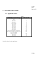
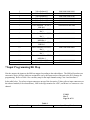
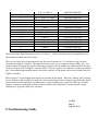
Top 1 or Tether 1
Top 2 or Tether 2
Top 3 or Tether 3 or Water 2
Top 4 or Tether 4 or Water 1
Tether 5
Tether 6
Tether 7
Tether 8
LMS1 or Tether 9
LMS2 or Tether 10
Tether 11
Tether 12
Tether 13
Tether 14
Tether 15
Tether 16
0000 0000 0000 0001
0000 0000 0000 0010
0000 0000 0000 0100
0000 0000 0000 1000
0000 0000 0001 0000
0000 0000 0010 0000
0000 0000 0100 0000
0000 0000 1000 0000
0000 0001 0000 0000
0000 0010 0000 0000
00000 0100 0000 0000
0000 1000 0000 0000
0001 0000 0000 0000
0010 0000 0000 0000
0100 0000 0000 0000
1000 0000 0000 0000
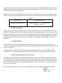
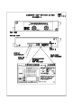
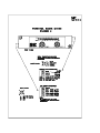
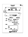
The location of the Input Connectors can be see in Figure 3. Notice each connector has assignments for one
input channel as noted in the above table.
There are two basic types of inputs based on the direction of current flow. We call the two types Positive
Common and Negative Common. The Inputs are factory set by way of a jumper to either of these type. One
word of caution, by setting the jumper for the mode of operation for the module, the whole module is that type
(Positive Common, PNP or Negative Common, NPN). There is no option for connector by connector setting of
type. If the tethered input module option is used, then each row of four inputs can be selected either Postive or
Negative Common.
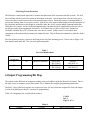
Refer to Figure 3 in selecting the desired mode of operation for the inputs. The terms “sinking” and “sourcing”
are not used due to the possibility of confusion. In our terminology, Positive Common is used when the load is
connected between the signal pins 2 and the positive voltage terminal pin 1 (typical for PNP logic switches).
Negative Common is used when the load is connected between the signal pins 2 and the negative voltage
terminal pin 3 (typical for NPN logic switches).
UI-024
Rev C
Page 15 of 19
8 Troubleshooting Guide