1
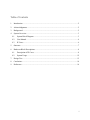
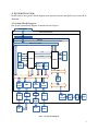
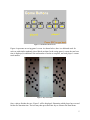
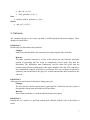
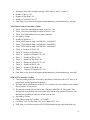
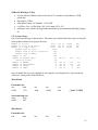
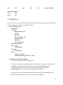
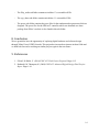
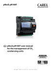
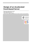
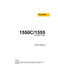
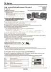
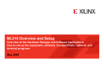
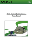
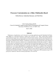
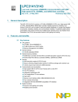
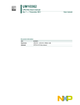
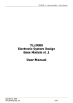
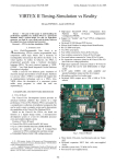
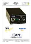
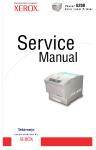
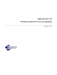
ENSC 452 - Simon Fraser University
ADVANCED DIGITAL SYSTEMS
Two Player Car Racing Game on
Xilinx V2 FPGA Board
Final Project Group Report
November 30, 2010
Group 1:
Yalda Hakki
Kia Filsoof
Table of Contents
1.
Introduction ............................................................................................................................. 2
2.
Acknowledgments ................................................................................................................... 2
3.
Background.............................................................................................................................. 2
4.
System Overview..................................................................................................................... 3
4.1
System Block Diagram..................................................................................................... 3
4.2
User Manual ..................................................................................................................... 4
4.3
IP Cores ............................................................................................................................ 6
5.
Outcome................................................................................................................................... 7
6.
Hardware Block Descriptions.................................................................................................. 8
6.1
Description of IP Cores .................................................................................................... 8
6.2
System Usage ................................................................................................................. 12
7.
Design Tree............................................................................................................................ 13
8.
Conclusion ............................................................................................................................. 14
9.
References ............................................................................................................................. 14
i
1. Introduction
For our ENSC 452 project, we have implemented a two-player car racing game on a Xilinx
Virtex II Pro FPGA board. Each car has a dedicated track and there are 3 tracks in total. Blocks
are randomly placed on the tracks and the placement of blocks is exactly the same on both tracks.
Upon collision between a car and a block, the car will be stopped. Players can speed up, speed
down, stop, reverse, and move diagonally with their cars at any time. In addition, music is played
at each state of the game. Finally, a timer indicates the duration of our race.
We chose this topic for our project because it sounded fun, and we were both excited to design a
video game’s hardware and software. Completion of this project has taught us a great deal about
digital hardware and software systems.
2. Acknowledgments
We would like to thank Dr. Lesley Shannon, our professor and Mr. Eric Matthews, our teacher
assistant for supervising us through this project and providing us with technical support.
3. Background
In the game console, the players are able to navigate to different states of the game, such as the
Main menu, Game Buttons menu, Play Game menu, and Exit menu. As mentioned in the
introduction, during the game, the players are able to accelerate forward, decelerate forward,
reverse, and move forward diagonally with their cars. Each player gets their own dedicated track
with randomly generated blocks which they must avoid to hit. These blocks are the same for both
players’ tracks. Upon collision of the cars with these blocks, their cars will be stopped and they
will need to accelerate from zero speed again. The players must complete three tracks before the
game is finished. The race time duration is displayed on the screen during the game. After
finishing the race, the game specifies which player has won and displays his/her finish-time on
the screen. The game repeatedly plays a specific song while in the Start and Game Buttons menu
and another song while in the Game Play menu.
The game uses a standard keyboard with PS2 ports as the user command interface, a monitor
with a VGA port for displaying images, and speaker/headphones with a TRS connector for
playing songs.
2
4. System Overview
In this section, our system’s block diagram, user interface manual, and the IP cores used will be
discussed.
4.1 System Block Diagram
Our overall system block diagram is shown below in Figure 1.
256 DDR SDRAM
XUPV2P Development Board
DIMM
FPGA Chip
DXCL2
IXCL2
MPMC (memory controller)
FSL2
ILMB2
ILMB
BRAM
DLMB
microBlaze0
UART
Controller
microBlaze2
Interrupt
Controller
FSL0
debug0
Random
Number
Generator
DLMB2
Timer
Counter
PLB2
PLB
PLB to
OPB
Bridge
MDM
VGA
Controller
JTAG
Video DAC
PS/2
Controller
OPB0
PS/2 ports
RS232 Port
USB
External
PC
BRAM
FSL1
AC97
controller
AC97
codec
Audio
Ports
speaker
XSGA
video port
Monitor
Keyboard
Figure 1. System Block Diagram
3
In the above system block diagram, we created the Random Number Generator ourselves. In
addition, the AC97 controller was obtained from a demo package on Xilinx’s website and is a
courtesy of Dr. Mike Wirthlin.
4.2 User Manual
Upon boot up of our game, the Start menu image will first be displayed to players shown below
in Figure 2.
Figure 2. Start Menu Screen
From this menu, the user can select Play Game to start a new game; select Game Buttons to view
the keyboard buttons used to navigate the cars; or select Exit to exit the game console. The user
may navigate through these selections by using the Up and Down arrow keys. The user may use
the Enter key to select the desired option.
Upon choosing the Game Buttons menu, the user will see the keyboard buttons used to navigate
the cars on the screen. The screen image corresponding to the Game Buttons is illustrates in
Figure 3. The user may then press the ESC key to return to the Start menu.
4
Figure 3. Game Buttons Menu Screen
Figure 4 represents our racing game’s screen. As shown below, there is a dedicated track for
each car with similar randomly placed blocks on them. In the racing game’s screen, the total race
time is displayed, in addition to the total number of tracks to complete, and each player’s current
track number.
Figure 4. Play Game Menu
Once a player finishes the race, Figure 5 will be displayed, illustrating which player has won and
his/her race duration time. The user may then press the Enter key to return to the Start Menu.
5
Figure 5. Winning Game Menu Screen
4.3 IP Cores
Most of the IP cores used for our project were provided from Xilinx. The Random Number
Generator was our only custom-designed IP core. Also, the OPB AC97 controller was obtained
from Xilinx website as a demo package. We made some minor modifications to the software
drivers of the OPB AC97 controller to make it suitable for the purpose of our project. All the IP
cores used in our system are listed below:
Xilinx
• microblaze_v7_10_d
• mpmc_v4_03_a
• xps_tft_v1_00_a
• xps_ps2_v1_00_a
• xps_uartlite_v1_00_a
• mdm_v1_00_d
• xps_intc_v1_00_a
• xps_timer_v1_00_a
• plbv46_opb_bridge_v1_00_a
• bram_block_v1_00_a
• lmb_bram_if_cntrlr_v2_10_a
• fsl_v20_v2_11_a
• lmb_v10_v1_00_a
• opb_v20_v1_10_c
6
•
•
plb_v46_v1_03_a
clock_generator_v2_01_a
Ours
• random_number_generator_v1_00_a
Others
• opb_ac97_v2_00_a
5. Outcome
The completed design of our system operated as initially planned with minor changes. These
changes are listed below.
Initial Plan 1:
Include only one Microblaze and system bus
Changes:
Added a second Microblaze and system bus for connecting the audio controller
Reasons:
The audio controller connects as a slave to the system bus and consumes noticeable
amount of processing and bus usage to continuously receive audio files from the
Microblaze. The Microblaze must continuously read the audio files itself from the
external memory before sending them to the audio controller. Since the VGA controller is
also continuously using the system bus to read image files, our car images would not be
updated as fast and noticed by the players if we had connected the audio controller to the
same bus.
Initial Plan 2:
Add a pause/resume feature for the player during game play.
Changes:
The user can only exit the current game by pressing ESC which will cause the system to
disregard the current game and return to the Start menu.
Reasons:
Due to time constraints we could not add this feature to the game.
Initial Plan 3:
Degrade the car’s speed by a specified amount upon collision with the sides of the blocks or
tracks.
7
Changes:
Our system only detects when collision with the cars and blocks or sides of the tracks has
occurred and prevents them from moving further in that direction. If the car has collided
with the sides of the track, its speed will not be affected. However if the car has collided
with the blocks, it will be stopped and must accelerate from zero speed.
Reasons:
Due to time constraints, we were not able to implement the complete speed degradation
feature for our game.
Our system could be further improved by adding initial plan 2 and 3 to our system. We could,
also, improve the game by improving the quality of our game graphics, such as the cars, blocks,
and tracks.
6. Hardware Block Descriptions
In this section, more details regarding the IP cores used for our project will be outlined. In
addition, the overall system usage of our project will also be described.
6.1 Description of IP Cores
The details regarding the IP cores used for our project are outlined below. We have not included
the information regarding standard IP cores such as the bram, ilmb, dlmb, fsl, opb, and clock
generator. More information regarding these cores may be found at the following link:
http://www.xilinx.com/support/documentation/ip_documentation.htm
Microblaze 0 (v7.10d)
• Used for controlling all peripherals except the AC97 controller, processing the game
logic, and controlling microblaze 2
• Provided by: Xilinx
• On chip memory: 64KB
• Cache: disabled
• Frequency: 100 MHz
• Number of FSL links: 3
• Main bus: PLB
• Debug: enabled
• Link:http://www.xilinx.com/support/documentation/sw_manuals/xilinx11/mb_ref_guide
.pdf
Microblaze 2 (v7.10d)
• Used for reading audio files from the SDRAM and sending them to the AC97 controller
to be played on the speakers
8
•
•
•
•
•
•
•
•
•
•
•
Microblaze 0 commands this microblaze through FSL on which song to be played
depending on which menu the user is currently in
Provided by: Xilinx
On chip memory: 64KB
Cache: enabled with XCL connection to the MPMC
Cache size: 8KB
Cach address range: 0x90000000 – 0x9fffffff
Frequency: 100 MHz
Number of FSL links: 2
Main bus: PLB
Debug: disabled
Link:http://www.xilinx.com/support/documentation/sw_manuals/xilinx11/mb_ref_guide.
pdf
Multi-Port Memory Controller (MPMC) (v4.03a)
• Used to control the data being read from or written to the external 256 MB SDRAM
through both microblazes and the TFT controller
• Provided by: Xilinx
• Memory range: 0x90000000 – 0x9fffffff
• Number of ports: 3
• Bus connections: SPLB0, XCL1, XCL2, MPMC_CTRL
• Link: http://www.xilinx.com/support/documentation/ip_documentation/mpmc.pdf
XPS Thin Film Transistor (TFT) Controller (v2.00a)
• Used to read 2MB blocks of image data continuously from the SDRAM and output them
to the external monitor
• Provided by: Xilinx
• PLB address range: 0xe0000000 – 0xefffffff
• Number of Slices: 424
• Number of flip-flops: 606
• Number of 4-input LUTs: 519
• Link: http://www.xilinx.com/support/documentation/ip_documentation/xps_tft.pdf
random_number_generator (v1.00a)
• Used to create 511 pseudo-random numbers using the linear feedback shift register
hardware architecture
• These numbers were used in the game for placing the randomly generated blocks
• We used ISE to create a test-bench for simulating our design before integrating it to our
project
9
•
•
•
•
•
Provided by: ourselves
Connected to microblaze 0 through an FSL link
Number of Slices: 5
Number of flip-flops: 9
Number of 4-input LUTs: 2
XPS PS2 Controller (v1.00a)
• Used for detecting user commands from the PS2 keyboard
• Provided by: Xilinx
• PLB address range: 0x70000000 – 0x700003ff
• Number of Slices: 272
• Number of flip-flops: 375
• Number of 4-input LUTs: 419
• Link: http://www.xilinx.com/support/documentation/ip_documentation/xps_ps2.pdf
XPS Uartlite (v1.00a)
• Used for providing RS232 communication between our system and an external PC
• Provided by: Xilinx
• PLB address range: 0x84000000 – 0x8400ffff
• Baud rate: 9600
• Data bits: 8
• Number of Slices: 115
• Number of flip-flops: 152
• Number of 4-input LUTs: 139
• Link: http://www.xilinx.com/support/documentation/ip_documentation/xps_uartlite.pdf
Microblaze Debug Module (MDM) (v1.00d)
• Used to allow debugging for our project through XMD running from an external PC
• Provided by: Xilinx
• PLB address range: 0x84400000 – 0x8440ffff
• Number of Slices: 272
• Number of flip-flops: 375
• Number of 4-input LUTs: 419
• Link: http://www.xilinx.com/support/documentation/ip_documentation/mdm.pdf
XPS Interrupt Controller (v1.00a)
• Used to handle multiple interrupts within our system and notify microblaze 0 accordingly
• Provided by: Xilinx
• PLB address range: 0x00010000 – 0x0001001f
10
•
•
•
•
•
Interrupts (from order of highest priority): PS2, timer_0, timer_1, timer_2
Number of Slices: 105
Number of flip-flops: 150
Number of 4-input LUTs: 117
Link: http://www.xilinx.com/support/documentation/ip_documentation/xps_intc.pdf
XPS Timer/Counter Controller (v1.00a)
• Timer_0 used for controlling the speed of player 1’s car
• Timer_1 used for controlling the speed of player 2’s car
• Timer_2 used for timing each race game’s duration
• Provided by: Xilinx
• Number of Instances: 3
• Timer_0 PLB address range: 0x01000100 – 0x010001ff
• Timer_1 PLB address range: 0x02000100 – 0x020001ff
• Timer_2 PLB address range: 0x03000100 – 0x030001ff
• Timer_0 - Number of Slices: 309
• Timer_0 - Number of flip-flops: 366
• Timer_0 - Number of 4-input LUTs: 345
• Timer_1 - Number of Slices: 309
• Timer_1 - Number of flip-flops: 366
• Timer_1 - Number of 4-input LUTs: 345
• Timer_2 - Number of Slices: 309
• Timer_2 - Number of flip-flops: 366
• Timer_2 - Number of 4-input LUTs: 345
• Link: http://www.xilinx.com/support/documentation/ip_documentation/xps_timer.pdf
OPB AC97 Controller (v2.00a)
• Used for reading audio files accessed by microblaze 2 and sent to the AC97 DAC to be
played from external speakers/headphones
• We made minor modifications to this IP core’s software drivers to make it more suitable
for the purpose of our project.
• The already existing software driver has a function called XAC97_PlayAudio. This
function does not perform conversion from little-endian to big_endian. Therefore, this
function was modified to take care of this issue as well.
• Provided by: Xilinx
• OPB address range: 0x73c00000 – 0x73c0ffff
• # of Slices: 195, # of flip-flops: 246, # of 4-input LUTs: 292
• Link: http://www.xilinx.com/univ/XUPV2P/Quickstarts/sysgen_audio/mb/audio.zip
11
OPB to PLB Bridge (v1.00a)
• Used to link the OPB bus connected to the AC97 controller to microblaze 2’s PLB
system bus
• Provided by: Xilinx
• PLB address range: 0x73c00000 – 0x73c0ffff
• # of Slices: 266, # of flip-flops: 268, # of 4-input LUTs: 412
• Link:http://www.xilinx.com/support/documentation/ip_documentation/plb2opb_bridge.p
df
6.2 System Usage
Our overall system usage is shown below. These data were obtained from the system_xst.srp file
in the synthesis folder of our project directory.
Number of Slices:
Number of Slice Flip Flops:
Number of 4 input LUTs:
Number used as logic:
Number used as Shift registers:
Number used as RAMs:
Number of IOs:
Number of bonded IOBs:
IOB Flip Flops:
Number of BRAMs:
Number of MULT18X18s:
Number of GCLKs:
Number of DCMs:
8575 out of 13696
10261 out of 27392
11014 out of 27392
9595
455
964
148
62 out of
556
92
98 out of
136
6 out of
136
8 out of
16
2 out of
8
62%
37%
40%
11%
72%
4%
50%
25%
Our executable file sizes were obtained by selecting the “Get Program Size” option under the
“Software” setting in the Xilinx EDK tool.
Microblaze0
Executable size:
text
data
31906
1576
bss
4608
dec
38090
hex
94ca
bss
dec
hex
(Total: 37.2 KB)
Stack and heap size:
stack
heap
0x400
0x0
Microblaze2
Executable size:
text
data
12
3502
300
1064
4866
1302
(Total: 4.75 KB)
Stack and heap size:
Stack
heap
0x400
0x0
7. Design Tree
In this section, the relevant folders/files required for within our project directory are listed and
described. Our project directory is divided as follows:
/g1_e452_final_project
system.xmp
/c_source
buttons_menu_conv
load.txt
play.wav
Play_audio_nov_24.c
project_nov24.c
start.wav
start_menu_conv
/edk_user_repository
/Play_Audio
executable.elf
/vga_demo
executable.elf
/pcores
/opb_ac97_v2_00_a
/random_number_generator_v1_00_a
Description of sub-folders and files:
- The system.xmp file is our Xilinx project file.
-
The c_source sub-folder contains our project’s source codes, image files, and audio files.
In addition, a load.txt file is included which can be used to download all of our
image/audio files onto the FPGA board. After opening XMD, type “source
c_source/load.txt”, to execute the commands inside this text file.
-
The edk_user_repository sub-folder contains the files required for importing the board
definition files and the drivers for the board’s specific peripherals.
13
-
The Play_audio sub-folder contains microblaze 2’s executable.elf file.
-
The vga_demo sub-folder contains microblaze 1’s executable.elf file.
-
The pcores sub-folder contains the pcore files for the random number generator which we
designed. The pcore files for the OPB ac97 controller which was obtained as a demo
package from Xilinx’s website is also found in this sub-folder.
8. Conclusion
We are grateful to have the opportunity of exploring digital hardware and software design
through Xilinx Virtex II FPGA boards. This project has increased our interest in these fields and
we both look forward to working on similar projects again in the near future.
9. References
1. Filsoof, K. Hakki, Y. (2010) ENSC 452 Final Project Proposal. Pages 1-15
2. Kubanski, M. Thompson, K. (2009) ENSC 452 Advanced Digital Design Final Project
Repor. Pages 1-16
14