1
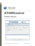
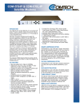
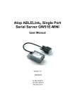
M105 - System Installation and User Manual MOST-Mobile satellite communication 1. Table of contents M105 - System Installation and User Manual 1 2.GENERAL DESCRIPTION 3 2.1.Antenna characteristics 3 2.2.Pedestal 3 2.3.Assembly 3 2.4.Environmental specification 3 3.Deployment and disassemble procedures 4 4.SYSTEM CONNECTIONS 4.2. MOST System Activation 9 10 5.SYSTEM OPERATION 11 5.2.ANTENNA CONTROL UNIT (ACU) INDOOR UNIT 11 5.3.ACU Menu Operations 5.3.1. Navigation: .2.3.5 Full mode operation: 11 12 13 2 MOST-Mobile satellite communication 2. General Description MOST terminals are based on patented technology, designed to meet the unique challenges of ground, marine and airborne needs for broadband satellite GEO communication. The low profile and lightweight design ensures best OTM performance. MOST efficient plug-in architecture of the electronic modules and control units, which combines transmission, reception and tracking capabilities with advanced stabilization system, ensures simple installation, maximum operational flexibility and minimum maintenance needs. 2.1. Antenna characteristics See technical datasheets for the specific model. 2.2. Pedestal Azimuth………………………………………………….…………………360° Continuous Elevation........……………………….................………............................ 6°-90° Polarization.......…………………………………….................... 180° Continuous Angular velocity...…………………………………..........AZ= 150°/S, EL= 200°/S Angular acceleration...…………………………………..AZ= 300°/S², EL= 400°/S² Ka Tracking accuracy.....…………………..………………..............................0.2° 2.3. Assembly Input power.....…………..…...... AC 110V-220V and DC 12V [optional 24V] Power Consumption ….(Including 20W BUC) 600W peak 400W average ODU NET Weight / dimensions.......................................... Weight 47Kg ODU NET dimensions…..See technical datasheets for the specific model ODU Wiring …………........………………….………..…….... One cable connection IDU NET Weight / dimensions… Rack 19” 1U Inc. DC/AC inv. Weight 6Kg 2.4.Environmental specification 2.4.1. Operating Temperature……………………………………….. -30°C to +55°C 2.4.2. Relative Humidity……………………………..……………………………….. 100% 2.4.3. Operating Altitude…………………………………………………. Max 25,000ft 2.4.4.Ground speed……………………………………………………….. Up to 350km/h 3 MOST-Mobile satellite communication 3. Deployment and disassemble procedures 3.1. General The deployment and disassemble procedures for the system vary according to the platform carrying the system (land vehicle, sea vessel or airborne platform). This manual refers to the system deployment in a land vehicle and to the corresponding disassembles from the vehicle. 3.2. Preliminary Steps Before deploying the system, perform the following steps: 1. Check the desired reception location according to the planed mission. 2. Park the vehicle in a suitable selected site, on a flat terrain. Make sure that the vehicle is parked on level and solid surface. 3. Check site for clear access to satellite. The primary requirement of any site is the availability of clear Line Of Sight (LOS) towards the designated satellite. Therefore, before deploying the equipment, select a site with no LOS obstruction between the system and the satellite. 4. Apply the vehicle hand brake. 5. Remove the MOST Outdoor Unit (ODU) from the vehicle and prepare it for mounting on the vehicle roof. 3.3. Mounting ODU on the flat surface To be coordinated with customer 3.4. Mounting ODU on Land Vehicle Two skilled personal are required for mounting the ODU on the vehicle roof. 4 MOST-Mobile satellite communication 3.4.1. Mounting ODU Directly on vehicle Roof 3.4.2. Mounting ODU with the MOST Roof Rack 3.4.2.1. Mounting the MOST Roof Rack on the vehicle with cross bars The MOST Roof Rack is connected to the two car cross bars with four hose clamps provided by the manufacturer (See Figure 4-1) Figure 4-1 5 MOST-Mobile satellite communication 3.4.2.2. Mounting the MOST Roof Rack on the car without cross bars The MOST Roof Rack is connected to the car roof with four hooks provided by the manufacturer (See Figure 4-2) Figure 4-2 3.4.2.3. Mounting the ODU on the MOST Roof Rack Connect slider provided by the manufacturer to the base of the system by fastening the screw. Pay attention: the slider have two centroid pins to make the slider in right direction (See Figure4-3) Figure 4-3 Attached the cover for the slider by fastening two screws (See Figure4-4) 6 MOST-Mobile satellite communication Figure 4-4 Connect tree other sliders in the same way (see Figure4-5) Figure 4-5 Slowly and carefully lift (two crew members) the ODU using the four handles, and place the ODU base at the edge of the ODU holder, so that the four guiding rods at the base bottom fit in the two holder slots. Gently slide the ODU base over its holder until it stops in place, and pull the ODU to the right until it stops (See Figure 4-6) Figure 4-6 7 MOST-Mobile satellite communication Close the two long handles at the holder sides until they reach the holder slots (See Figure 4-7) Lock the handles by manually tightening with a wrench. Figure 4-7 Secure the handles by inserting the locking pins [two pins]. Figure 4-8 8 MOST-Mobile satellite communication 4. System connections 4.1. Cable connection Before proceeding, make sure that the Power Supply (PS) drawer front panel is set to OFF position. To prevent any damage, be careful when handling and connecting the system cables. 1. Connect the main cable between the outdoor unit (ODU) and Indoor Unit (IDU-ACU) as follows: a. Connect the main cable ODU plug to the corresponding receptacle on the ODU main box (below the ODU base). b. Connect the main cables Receive (Rx) and Transmit (Tx) N-type plugs to the corresponding Rx and Tx receptacles on the panel of the ODU. c. Connect the main cable IDU plug connector to the IDU receptacle on the rear panel of the ACU. d. Connect the main cables Receive (Rx) and Transmit (Tx) N-type plugs to the corresponding Rx and Tx receptacles on the rear panel of the satellite modem [Ex. CDM-570L-IP]. e. In some models you need to connect the 7pin fan power harness between ODU panel and Radom Fans power connector [see fig.5-1]. 2. Connect an Ethernet cable between the LAN receptacle between the host equipment drawer [Ex. Video encoder/ WIFI backhaul / cellular backhaul] rear panel and the Traffic 100 receptacle on the satellite modem rear panel. 3. Connect an Ethernet cable between the LAN receptacle on the ACU drawer rear panel and the operator's PC. 4. Connect a control cable [D type 9pin] between the remote control receptacle on the satellite modem rear panel and the ACU AUX connector. 5. Connect the 12V power from the vehicle to the ACU. 9 MOST-Mobile satellite communication 4.2. MOST System Activation 1. Sequentially set the POWER SW, [on the ACU front panel] to ON, to activate the system. Once the System is activated, it automatically starts self-test and self-calibration process for a duration of about 30 seconds. Now the system is ready and operator may choose to operate the system from the ACU or from external PC. 2. . Check that in the System Status and Alarm (see Figure 5-2.) LED illuminates in green (indicating that the ACU is communicating with ODU). 3. If user is connected to a PC, Turn the PC on, and operate the control program that enables remote control and monitoring of the system from the PC. Check that the MOST control station window is displayed and active. MAIN I/O BOX FAN POWER CONNECTOR RX TX MAIN CONNECTOR TO INDORE UNIT (ACU) MOST Antenna Control Unit Opt. PWR IN 220V PWR IN 12VDC TX Modem RX AUX 220V OUT Figure 5-1 01 MOST-Mobile satellite communication 5. System operation 5.1. Antenna Control Unit-Indoor Unit Display Front view Navigation Keys SYS Status LAN LAN status AC IN Back view DC IN LAN PWR AC out Fuse AC OUT ODU M&C Figure 5-2 5.2.Antenna Control Unit (ACU) Indoor Unit • Controlling the system can be done directly from the ACU • Indoor unit supply power to the system • Modem monitoring (optionally) • Input : 12VDC [optional 24V] or 220VAC [optional 110VAC] • Output: AC 220V(optional 110V) 5.3. ACU Menu Operations The ACU has two operations modes, full and basic. From the full mode user can change almost every parameter in the system, monitor the system and insert the system to build in test (BIT) mode. Important Note: Changing these parameters can cause the system to malfunction. Changes should only be made by a qualified technician. From basic mode user can change only chosen parameters, the selected preset, rescan, BUC activation and insert the system to standby. User can see the SNR, System status and GPS status. 00 MOST-Mobile satellite communication 5.3.1. Navigation: To navigate from section to section it is through the arrows left and right. To enter to submenu, set parameter or execute command press OK. To go back to main-menu or back to the title without change press BACK. To cancel the changing in combo-box, numeric-box and text-box press CLEAR. To change value in combo-box, numeric-box and text-box press UP or DOWN. Note: this is the general navigation there is a submenus, with deferent keyboard operation. It will be describe in the specific submenu. 02 MOST-Mobile satellite communication 5.3.2. Full mode operation: 1. Open menu The open menu is the startup menu and the standby menu. In this menu we can see the ACU type (12V or 24V) , system status, SNR in dB, the transmit status, GPS status and the modem status if connected and support .To exit from this menu need to press on any key, after startup we will move to Main menu and in standby scenario we will return to last menu. 2. Main menu In this menu we can enter to Config menu, Monitor menu, BIT menu and TX menu. we can also execute Rescan and see the transmit status, system status (Stat), GPS status and the SNR in dB. To avoid duplication we can see the parameters values in Config menu. 2.1. Config menu From this menu we can enter to Satellite menu, BUC menu, Modem menu, Pointing menu, ODU-Network menu, ACU-Network menu, RX menu, Utilities (Util) menu and Default parameter (Dflt-Prm) menu. 2.1.1. Satellite menu: When we enter to this menu the blinking icon is the selected preset. For select other preset or changing preset you need to enter to this preset. 2.1.1.1. Preset # menu: In this menu we can select the preset or enter to changing menu. 2.1.1.1.1. Select: Press OK will select this preset and go back to satellite menu. 2.1.1.1.2. Change menu: In this menu we can change the preset properties. Note: If you change preset and you want to apply this preset you must to select him! 2.1.1.1.2.1. Name: This is the satellite name, for changing the name you can enter by press OK to changing mode. In changing mode by press UP or DOWN you can change the blinking letter from the built-in satellite list, you can also by press RIGHT or LEFT move from letter to letter. After you find the satellite name you must verify correct coordinates. 2.1.1.1.2.2. Pol: In this we can change the polarization mode. For changing polarization press OK to changing 03 MOST-Mobile satellite communication mode. In changing mode by press UP or DOWN you can select the prefer polarization. In general we have 4 polarizations mode: H – Horizontal, V – Vertical, R – Circular Right and L – Circular Left. Note: Not all the options are exist in all system, it is depends in the system type. 2.1.1.1.2.3. Freq: This indicates the beacon center frequency. For changing center frequency press OK to changing mode. In changing mode by press UP or DOWN you can change the blinking digit, you can also by press RIGHT or LEFT mode from digit to digit. 2.1.1.1.2.4. BW: This indicates the beacon Bandwidth. For changing Bandwidth press OK to changing mode. In changing mode by press UP or DOWN you can change the blinking digit, you can also by press RIGHT or LEFT mode from digit to digit. 2.1.1.1.2.5. Mode: This indicates the beacon algorithm, the algorithm should be determine from the beacon type. Beacon Mode for clean carrier and Rssi for other carriers. 2.1.2. BUC menu: In this menu we can change the BUC Gain. Note: For change the transmit status (On/Off) you need to enter to TX menu. 2.1.2.1. Gain: This is the BUC gain. For changing the BUC gain press OK to changing mode. In changing mode by press UP or DOWN you can change the blinking digit, you can also by press RIGHT or LEFT mode from digit to digit. 2.1.3. GPS menu: In this menu we can select the GPS source. Normally the system works with the internal GPS. If for some reasons the internal GPS not locked, you can enter manually the coordinates. When we enter to this menu the blinking icon is the selected source. 2.1.3.1. Internal GPS: Press OK on this will select the internal GPS. 2.1.3.2. External GPS menu: When you enter to this menu the GPS source immediately change to external, So you must update the correct coordinates or switch back to internal GPS. 2.1.3.2.1. Lat: This is the Latitude in degrees, N – North and S - South . For changing the Latitude press OK to changing mode. In changing mode by press UP or DOWN you can change the blinking digit, you can also by press RIGHT or LEFT mode from digit to digit. 2.1.3.2.2. Long: This is the Longitude in degrees, E – East and W - West . For changing the Longitude press OK to changing mode. In changing mode by press UP or DOWN you can change the blinking digit, you can also by press RIGHT or LEFT mode from digit to digit. 04 MOST-Mobile satellite communication 2.1.4. Modem menu: In this menu we can change the modem type. The ACU support in few modems and require connection from ACU and Modem. 2.1.4.1. Type: This is the Modem type. For changing the Modem type press OK to changing mode. In changing mode by press UP or DOWN you can select from list. The supported modems are listed in MOST web site. 2.1.5. Pointing menu: In this menu we change the pointing mode. normally the system will be in Auto mode or standby, the other two modes are manual operation. When you enter to this menu you can see the pointing mode. 2.1.5.1. Auto: Press OK on this will select Auto mode. After changing the mode if you need communication you must execute Rescan. 2.1.5.2. Joystick menu: In this mode we can control the manually on the pointing. The Joystick mode moves the pointing continuously. We can see the SNR for know if we pointing are correct. 2.1.5.2.1. Az: This is the Azimuth pointing in degree, 0 – north, 90 – east, 180 – south and -90 west. The west is in negative number and the east is positive. Press UP or DOWN for change, there is no changing mode. 2.1.5.2.2. El: This is the Elevation pointing in degree, the degree is related to parallel to earth, 0 – parallel to earth and 90 – perpendicular to earth[zenith]. Press UP or DOWN for change, there is no changing mode. 2.1.5.2.3. Pol: This is the Polarization pointing in degree, the degree is related to perpendicular to earth, 0 – perpendicular to earth and ±90 – parallel to earth [zenith]. Press UP or DOWN for change, there is no changing mode. 2.1.5.3. Position menu: In this mode we can control the manually on the pointing. The Position mode moves the pointing to given pointing. We can see the SNR for know if we pointing are correct. Note: The reading is approximate so it is recommended to given the right pointing and does the adjustment in Joystick mode. 2.1.5.3.1. Az: This is the Azimuth pointing in degree, 0 – north, 90 – east, 180 – south and -90 west. The west is in negative number and the east is positive. For changing the Azimuth pointing press OK to changing mode. In changing mode by press UP or DOWN you can change the blinking digit, you can also by press RIGHT or LEFT mode from digit to digit. 05 MOST-Mobile satellite communication 2.1.5.3.2. El: This is the Elevation pointing in degree, the degree is related to parallel to earth, 0 – parallel to earth and 90 – perpendicular to earth [zenith]. For changing the Elevation pointing press OK to changing mode. In changing mode by press UP or DOWN you can change the blinking digit, you can also by press RIGHT or LEFT mode from digit to digit. 2.1.5.3.3. Pol: This is the Polarization pointing in degree, the degree is related to perpendicular to earth, 0 – perpendicular to earth and ±90 – parallel to earth [zenith]. For changing the Polarization pointing press OK to changing mode. In changing mode by press UP or DOWN you can change the blinking digit, you can also by press RIGHT or LEFT mode from digit to digit. 2.1.5.4. Standby: Press OK on this will select Standby mode. In this mode the motor are disabled and transmit in off. In this mode keep the system warm and ready to work. 2.1.6. Odu-Network menu: From this menu we can enter to Set the ODU network menu and Set the ACU connection to ODU menu. Note: If the ODU IP and the ACU IP not in the same network, the ACU cannot connect to ODU. 2.1.6.1. Set the ODU network menu: In this menu we change the ODU network properties. If you work in static mode you must to know the network rules. 2.1.6.1.1. Mode: We have three supported mode. Static – static IP configuration. DHCP – Get the IP configuration from DHCP server. DHCP with time out – Try to get the IP configuration from DHCP server, if the time out is over go to static configuration. 2.1.6.1.2. IP menu: Change the ODU IP, this is also the way to see the ODU IP. Press UP or DOWN you can change the blinking digit, you can also by press RIGHT or LEFT mode from digit to digit. 2.1.6.1.3. Subnet Mask menu: Change the ODU Subnet mask, this is also the way to see the ODU Subnet mask. Press UP or DOWN you can change the blinking digit, you can also by press RIGHT or LEFT mode from digit to digit. 2.1.6.1.4. Gateway menu: Change the ODU Gateway, this is also the way to see the ODU Gateway. Press UP or DOWN 06 MOST-Mobile satellite communication you can change the blinking digit, you can also by press RIGHT or LEFT mode from digit to digit. 2.1.6.1.5. Timeout menu: Change the ODU Timeout, this is also the way to see the ODU Timeout. Press UP or DOWN you can change the blinking digit, you can also by press RIGHT or LEFT mode from digit to digit. 2.1.6.2. Set the ACU connection to ODU menu: In this menu we set the way that the ACU will find the ODU IP. When you enter to this menu you will see the current mode blinking. 2.1.6.2.1. Static IP: Set static IP, if the ODU IP is incorrect the ACU cannot connect to the ODU. 2.1.6.2.1.1. IP: Press UP or DOWN you can change the blinking digit, you can also by press RIGHT or LEFT mode from digit to digit. 2.1.6.2.2. Broadcast: Find the ODU with broadcast message, the ACU send the broadcast message only to the ODU so you can work in this mode also if you have more than one MOST SYSTEM in the network. The ACU will not find the ODU if they are not in the same network. If in this mode the ACU not find the ODU and you don’t know the ODU IP you need to go to recovery mode. 2.1.6.2.3. Recovery: In recovery mode the ACU disconnect the all other ports (AUX1, AUX2 and USER) and try to find the ODU with broadcast message, the main different between Recovery mode and Broadcast mode is that in Recovery mode we send also illegal messages. Note: In this mode you can only change the Network parameters; the only way to exit from this mode is by shutdown the system and power up. 2.1.7. Acu-Network menu: In this menu we change the ACU network properties. If you work in static mode you must to know the network rules. Note: If the ODU IP and the ACU IP not in the same network, the ACU cannot connect to ODU. 2.1.7.1. Mode: We have three supported mode. Static – static IP configuration. DHCP – Get the IP configuration from DHCP server. DHCP with time out – Try to get the IP configuration from DHCP server, if the time out is over go to static configuration. 2.1.7.2. IP menu: 07 MOST-Mobile satellite communication Change the ACU IP, this is also the way to see the ACU IP. Press UP or DOWN you can change the blinking digit, you can also by press RIGHT or LEFT mode from digit to digit. 2.1.7.3. Subnet Mask menu: Change the ACU Subnet mask, this is also the way to see the ACU Subnet mask. Press UP or DOWN you can change the blinking digit, you can also by press RIGHT or LEFT mode from digit to digit. 2.1.7.4. Gateway menu: Change the ACU Gateway, this is also the way to see the ACU Gateway. Press UP or DOWN you can change the blinking digit, you can also by press RIGHT or LEFT mode from digit to digit. 2.1.7.5. Timeout menu: Change the ACU Timeout, this is also the way to see the ACU Timeout. Press UP or DOWN you can change the blinking digit, you can also by press RIGHT or LEFT mode from digit to digit. 2.1.8. RX menu: In this menu we can change attenuation to modem and the 10MHz clock source. 2.1.8.1. Att to modem: This is the attenuation to modem in dB. For changing the attenuation press OK to changing mode. In changing mode by press UP or DOWN you can change the blinking digit, you can also by press RIGHT or LEFT mode from digit to digit. 2.1.8.2. 10MHz Source: In this we can change the 10MHz clock source. For changing clock source press OK to changing mode. In changing mode by press UP or DOWN you can select the source. In general we have 2 sources: Internal – the internal OCXO, Modem – The Modem OCXO. Note: If you select Modem you must verify that the modem support in this. 2.1.9. Util menu: From this menu we can enter to Acu id menu, Operation mode (Opmode) menu and LDC menu. 2.1.9.1. Acu id menu: The ACU ID is for convenience for follow the ACU unit in the factory. Change the ACU ID. Press UP or DOWN you can change the blinking Character, you can also by press RIGHT or LEFT mode from Character to Character. 2.1.9.2. Opmode menu: In this menu we change the ACU operation. 08 MOST-Mobile satellite communication 2.1.9.2.1. Menus mode: There is two menus modes , Full or Basic. For changing menus modes press OK to changing mode. In changing mode by press UP or DOWN you can select the menus modes. 2.1.9.2.2. Send Status: The ACU send cycles status to ODU and GUI (if exist in the system), there is situations that we connect to one ODU two ACU for two separated control location. Only the ACU that connect direct to ODU need to send the status. For changing send cycles status press OK to changing mode. In changing mode by press UP or DOWN you can select On/Off. 2.1.9.3. LCD menu: In this menu can change the LCD view and standby screen operation. 2.1.9.3.1. Contrast: The LCD Contrast. For changing the LCD Contrast press OK to changing mode. In changing mode by press UP or DOWN you can change the blinking digit, you can also by press RIGHT or LEFT mode from digit to digit. 2.1.9.3.2. Backlight: The LCD Backlight. For changing the LCD Backlight press OK to changing mode. In changing mode by press UP or DOWN you can change the blinking digit, you can also by press RIGHT or LEFT mode from digit to digit. 2.1.9.3.3. Standby screen timer: You can select if you want standby screen (the Goodies menu) after specified time. For changing operate timer press OK to changing mode. In changing mode by press UP or DOWN you can select On/Off. 2.1.9.3.4. Wait: The time that the system wait before enter to standby screen. For changing the Waiting time press OK to changing mode. In changing mode by press UP or DOWN you can change the blinking digit, you can also by press RIGHT or LEFT mode from digit to digit. 2.1.10. Dflt-Prm: NOT SUPPORT IN THIS VERSION! 2.2. Monitor menu: From this menu we can enter to Version (Ver) menu, Rx menu, Gps menu, Modem menu, Motors menu, Fault (Flt) menu, Inverter menu, Pointing menu, System current (Sys Crnt), Cubic menu and Compass menu. 2.2.1. Ver menu: View the version of all the system parts. 2.2.1.1. ACU: View the ACU Hardware version and Software version. 09 MOST-Mobile satellite communication 2.2.1.2. ODU: View the ODU Hardware version and Software version. 2.2.1.3. MB1: View the Microblaze1 Hardware version and Software version. 2.2.1.4. MB2: View the Microblaze2 Hardware version and Software version. 2.2.1.5. MC1: View the Microcontroler1 Hardware version and Software version. 2.2.1.6. MC2: View the Microcontroler2 Hardware version and Software version. 2.2.1.7. BUC: View the BUC Hardware version and Software version. 2.2.1.8. Cubic: View the Cubic Hardware version and Software version. 2.2.2. RX menu: View the PLLs status and SNR in dB. 2.2.3. BUC menu: View the Buc temperature and transmit power. Note: Not all the BUCs support in these monitors. 2.2.4. GPS menu: View the internal GPS status (Stat), the system GPS source, the coordinates (Lat – Latitude, Long – Longitude and Altit – Altitude). The Next for more GPS status. 2.2.4.1. Next: View the GPS Mode, The number of satellite in view (Num of Sat V), the Date and GMT. 2.2.5. Modem menu: View if Modem Status, Receive Level (RSL) Eb/N0 and Bit Error Rate (BER). 21 MOST-Mobile satellite communication 2.2.6. Motor menu: From this menu we can enter to motors monitoring. 2.2.6.1. Primary azimuth: View the Primary azimuth Status (Status), Bus voltage, Motor Current and Motor temperature. 2.2.6.2. Secondary azimuth: View the Secondary azimuth Status (Status), Bus voltage, Motor Current and Motor temperature. 2.2.6.3. Elevation: View the Elevation Status (Status), Bus voltage, Motor Current and Motor temperature. 2.2.6.4. Polarization: View the Polarization Status (Status), Bus voltage, Motor Current and Motor temperature. 2.2.7. Flt menu: View the active Fault. Press UP or DOWN for view all active faults. Part of the Fault you can clear by click on CLEAR button. 2.2.8. Inverter menu: View the inverter state, output voltage, output current and output power. 2.2.9. Pointing menu: View the pointing location. 2.2.10. Sys crnt menu: View the system currents, the digital part, cubic heater, BUC and motors. 2.2.11. Cubic menu: View the Azimuth gyro rate, Elevation gyro rate and the temperature. The Next for more Cubic status. 2.2.11.1. Next: View the Elevation inclinometer and the Polarization inclinometer. 2.2.12. Compass menu: View the Compass temperature, X magnetic read, Y magnetic read and Z magnetic read. 20 MOST-Mobile satellite communication 2.3. BIT menu: From this menu we can enter to Fun menu. 2.3.1. Fan menu: When you enter to this menu you immediately go to test mode and see the fan status. When you exit from this menu you exit from test mode. 2.3.1.1. Internal: For changing internal fun state press OK to changing mode. In changing mode by press UP or DOWN you can select On/Off. 2.3.1.2. External: For changing external fun state press OK to changing mode. In changing mode by press UP or DOWN you can select On/Off. 2.4. Rescan: Execute rescan. Work in Auto mode (Pointing) 2.5. Tx menu: Enter for change the transmit state. 2.5.1. Tx: Select the wanted transmit state. 22