1
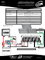
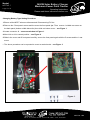
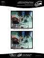
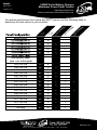
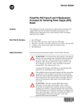
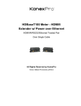
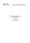
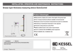
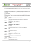
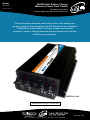
Model: MPPT60-1 Page 1 of 8 3400W Solar Battery Charger Maximum Power Point Tracker Operating Instructions Please read these instructions before use This revolutionary maximum power point tracker solar charger was designed using the technology that won GSL Electronics the prestigious “2008 EDN Innovation award”. A simple, compact and low cost alternative. Ideal for charging batteries with the new low cost and high efficiency grid type panels. MPPT60-1 Unit PATENT APPLIED FOR - 2010901565 MPPT60-1-R8 Unit 2, 110 Station Road, Seven Hills ,NSW, 2147, Australia Model: 3400W Solar Battery Charger Maximum Power Point Tracker MPPT60-1 Page 2 of 8 Operating Instructions Please read these instructions before use MPPT60-1 Specifications Efficiency typical 97% Input voltage Output voltage 16V to 95V Float 13.5V / 27V / 54V Absorption – Vented LA batteries 14.5V / 29V / 58V – Sealed LA batteries 14.2V / 28.4V / 56.8V Output power 3400W / 60A MAX Quiescent current 0.05A Thermal protection Multilevel Type Dimensions (mm) 255 X 145 X 67mm Indications LED display – OUTPUT STATUS Basic Wiring Instructions: Panel + Panel - Connected Disconnected MIHV Remote LED MIHV Battery + MPPT Battery Note: First start up may take up to one minute. * Optional Diode MPPT60-1-R8 Unit 2, 110 Station Road, Seven Hills ,NSW, 2147, Australia Model: 3400W Solar Battery Charger Maximum Power Point Tracker MPPT60-1 Page 3 of 8 Operating Instructions Please read these instructions before use The MPPT60-1 is designed to charge sealed and vented lead acid batteries from photovoltaic pannels. Silicon based panels such as monocrystalline, polycrystalline and amorphous are suitable. MPPT60-1 General Information: • Green LED On – Battery Ok. • Green LED Flashing – Battery Low. • This MPPT is designed to auto detect 12V, 24V or 48V battery systems and select a suitable charge regime. • The MPPT 60-1 is shipped in a sealed battery setting which is the safest setting but if your batteries are vented then, BEFORE wiring the MPPT, follow the CHANGING BATTERY TYPE SETTING PROCEDURE. • The maximum absorption voltage is 14.5V, 29V or 58V and the float voltage is 13.5V, 27V or 54V for 12V, 24V or 48V batteries respectively. • The Absorption Mode is entered following a “low battery condition” at dawn and that mode is maintained for the remainder of the day. If the battery is not in a “low condition” at dawn then the Maintenance (Float) Mode is entered and that mode is maintained for the remainder of the day. • Custom float and absorption voltages and thresholds are possible but minimum orders apply. • This MPPT has a built in multilevel over temperature protection to improve product reliability while maximising output power availability. • The maximum continuous output power is 3400W in 48V systems, 1700W in 24V systems and 850W in 12V systems. The output current is limited to 60A. MPPT60-1-R8 Unit 2, 110 Station Road, Seven Hills ,NSW, 2147, Australia Model: 3400W Solar Battery Charger Maximum Power Point Tracker MPPT60-1 Page 4 of 8 Operating Instructions Please read these instructions before use WARNING • DO NOT Disconnect battery and/or load whilst charger is operating. Disconnect charger from the PV first • IF the optional Diode is not installed then shorting the panels when the batteries are connected may damage the MPPT Important notes: • This MPPT should only be operated with a suitable battery connected. • To enhance Battery and load protection the use of the MIHV or equivalent is recommended • Before any maintenance ensure that the panels are disconnected or de-energised. • Use only PV Systems with open circuit voltage below 95V • This equipment must be installed by qualified personnel only and incorrect wiring can cause fire, injury or death – GSL will accept no responsibility for MPPT misconnection or misuse. • Use only sealed or vented 12V, 24V or 48V lead acid batteries and confirm the MPPT settings, charge voltages and currents are correct for your battery system – if in any doubt seek qualified advice! • Use wires suitable for at least 80A, but if wire runs are over 3m then larger wires are recommended to limit voltage drop and losses. • Install the unit in a dry place out of direct sunlight and away from flammable liquids or gases. • Battery fuse ( BF ) is always required and must be located as close to the battery as possible, its sizing depends on the wire size and load ratings. Typically a 80A 60VDC fuse would do. • Before connecting the battery always check the battery and PV panel polarity. • Optional Diode A suitably heatsinked schottky diode rated at or above 80A 60V (its anode connected to the + panel and cathode to the MPPT + input white wire) may be used, see wiring diagram. This diode will protect against panel short and block any voltage on the panel but will slightly decrease the battery charge current. • The lowest Maximum Power Point system voltages are 18V for 12V batteries, 36V for 24V batteries and 72V for 48V batteries to ensure full output power. MPPT60-1-R8 Unit 2, 110 Station Road, Seven Hills ,NSW, 2147, Australia Model: MPPT60-1 Page 5 of 8 3400W Solar Battery Charger Maximum Power Point Tracker Operating Instructions Please read these instructions before use Changing Battery Type Setting Procedure 1.Ensure all the MPPT wires are disconnected. Disconnecting PV first. 2.Remove the 5 front panel screws and the move the front panel ajar. Then remove 1 middle rear screw on the back panel (bottom middle below fan) then slide out bottom cover – see Figure 1. 3.Locate connector J4 – see zoom window in Figure 1. 4.Move link on J4 to vented position – see Figure 2. 5.Slide in the cover and fit front panel carefully, secure the front panel again with the 5 screws and the 1 rear screw. • The above procedure can be repeated to revert to sealed mode – see Figure 3. Figure 1. MPPT60-1-R8 Unit 2, 110 Station Road, Seven Hills ,NSW, 2147, Australia Model: MPPT60-1 Page 6 of 8 3400W Solar Battery Charger Maximum Power Point Tracker Operating Instructions Please read these instructions before use Figure 2 (Above): Vented Battery Setting Figure 3 (Above): Sealed Battery Setting MPPT60-1-R8 Unit 2, 110 Station Road, Seven Hills ,NSW, 2147, Australia Model: MPPT60-1 Page 7 of 8 3400W Solar Battery Charger Maximum Power Point Tracker Operating Instructions Please read these instructions before use MPPT FAQs Q: What is an MPPT? MPPT stands for Maximum Power Point Tracker and is a specialized converter designed to maintain the PV voltage at the level in which it delivers maximum power to the load or battery. The panel’s nominal output power can only be obtained with the use of an MPPT. Q: What are the GSL MPPT’s advantages compared to standard solar regulators? 1. Suitable for lower cost non battery type PV since the MPPT can efficiently charge the batteries from relatively high voltage, say 24V batteries from 40Vmp panels. 2. Less interference and more accurate voltages during absorption and float. Q: What sorts of loads can I power with the MPPT60-1? 1.The maximum bulk charge current with the MPPT60-1 on a 12V battery and 800W panel is approximately 60A, so you can expect about 200Ah per day which means a 200W load for about 10 hours daily. 2. Following the same reasoning with a 24V 1600W panel the MPPT60-1 will supply a daily load of 400W for about 10 hours. 3. Following the same reasoning with a 48V 3200W panel the MPPT60-1 will supply a daily load of 800W for about 10 hours. Q: Why are MPPT not more common in standalone solar systems? Until now and despite their overwhelming advantages MPPTs have not been commonly used in standalone solar systems because of cost. The new GSL MPPT specifically addresses this issue making economic sense in a wide range of solar systems. Q: What sort of batteries should I use? 1. A deep cycle battery is a must due to the cyclical nature of the solar system with a recommended battery capacity of at least 180Ah. 2. A larger battery will not only give longer run time during low light but also will be able to avoid available PV power being unstored such as when the battery reaches the float stage. Q: How do PV temperatures affects charge current? Temperature increase brings down the PVs maximum power point voltage reducing the MPPTs current gain available. In principle at 25C it is possible to achieve 30% gain but at 40C, a more realistic average temperature, about 20% is still available. Q: What happens at low PV currents? The MPPT will outperform the conventional regulator above 3% of nominal panel power. Below 3%, about 10W in a 400W panel, the MPPT will have a slightly lower output current than a non MPPT. Q: Is interference possible? and If so what do I do? GSL’s MPPTs produce far less interference than a conventional solar regulator during the absorption and float stages, that is during most of its operating time, and its designed to comply with local and international EMI standards however some interference is still possible. If interference occurs first try and reorient the aerial or move the sensitive equipment away from the MPPT wires. Ensure the MPPT chassis is grounded. Grounding a battery terminal may also help and finally you can try adding ferrite clamps. Warranty Conditions: Our products come with guarantees that cannot be excluded under the Australian Consumer Law. The customer is entitled to a replacement or refund for a major failure and compensation for any other reasonably foreseeable loss or damage. The customer is also entitled to have the products repaired or replaced if the products fail to be of acceptable quality and the failure does not amount to a major failure. GSL Electronics (GSL) warrants that its products will, under normal use and service, be free of defects in material and workmanship for a period of two (2) years from the date of the original purchase by the customer as marked on the customer’s original invoice. Please refer to our website for full warranty and return information which can be found at http://www.gsl.com.au/faq.html MPPT60-1-R8 Unit 2, 110 Station Road, Seven Hills ,NSW, 2147, Australia Model: 3400W Solar Battery Charger Maximum Power Point Tracker MPPT60-1 Page 8 of 8 Operating Instructions Please read these instructions before use g gin g ar gin 1x18 Cell Grid 1x48 Cell Grid 2x48 Cell Grid 3x48 Cell Grid 1x52 Cell Grid 2x52 Cell Grid 3x52 Cell Grid 1x54 Cell Grid 2x54 Cell Grid 3x54 Cell Grid 1x60 Cell Grid 2x60 Cell Grid 1x72 Cell Grid 2x72 Cell Grid 10 28 56 84 31 62 93 32 64 96 36 72 44 88 8 23 46 69 25 50 75 26 52 78 29 58 36 72 1x96cgsp 65 55 48 V Ch ar Ch 24 V 12 V 16 32 48 64 32 64 M P V 21 42 63 84 42 84 OC V Ch ar gin g For optimal performance from panel and MPPT please use the following table to determine the best setup for your situation. Grid Connect Panel (size = no. cells in grid) MPPT60-1-R8 Unit 2, 110 Station Road, Seven Hills ,NSW, 2147, Australia