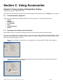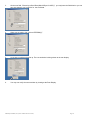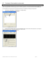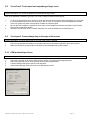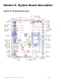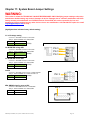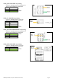
1
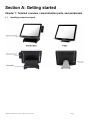
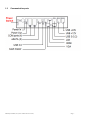
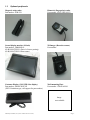
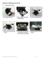
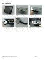
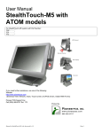
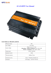
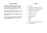
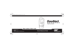
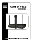
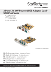
User Manual CYPRUS Core Pentium & Core i-Series For further assistance, contact us: Tel Web Email Drivers : 909-468-9757 option 2 : www.pioneerpos.com : [email protected] : http://www.pioneerposftp.com Manual for CYPRUS (V1.0) (Core Pentium & Core i-Series) Page 1 Important Note This manual is ONLY intended for Cyprus system with Part Number below: QCxxxxxxxxxx SCxxxxxxxxxx UCxxxxxxxxxx WCxxxxxxxxxx Disclaimer Information in this document is subject to change without notice. PioneerPOS shall not be liable for technical or editorial errors in this document. This manual contains proprietary information which is protected by copyright. No parts of this document may be photocopied, reproduced, or translated to another language without prior written consent of Pioneer POS Solutions Inc. Trademarks used in this manual: PioneerPOS and PioneerPOS Logo are trademarks of Pioneer POS Solutions Inc. Microsoft Windows, Windows are trademarks of Microsoft Corporation. © 2015 PioneerPOS Solutions Inc. All rights reserved. Target Audience This Manual is written for technically qualified personnel. It is not intended for general audiences. Warranty Exclusions The warranty will NOT apply to damages caused by: Unauthorized modification or abuse. Improper or inadequate maintenance by customer. Conventions The following conventions are used in this manual: [Warning] A WARNING message indicates a potential for personal injury or death. [Caution] A CAUTION message indicates potential damage to hardware or loss of data [Note] A NOTE contains additional important information to help you in servicing the system. Manual for CYPRUS (V1.0) (Core Pentium & Core i-Series) Page 2 Table of Content Table of Content .................................................................................................................................................................... 3 Introduction ........................................................................................................................................................................... 4 About this guide .................................................................................................................................................................... 4 System specification ............................................................................................................................................................ 5 Section A: Getting started .................................................................................................................................................... 6 Chapter 1: Terminal overview, communication ports, and peripherals ............................................................................. 6 Chapter 2: Setting Up Terminal........................................................................................................................................... 9 Section B: Using Touchscreen Terminal .......................................................................................................................... 12 Chapter 3: Touch screen calibration (if needed) .............................................................................................................. 12 Chapter 4: Network........................................................................................................................................................... 15 Chapter 5: Serial port (RS232, COM ports) ....................................................................................................................... 17 Section C: Using Accessories ........................................................................................................................................... 20 Chapter 6: Using Customer Display/Rear Display ............................................................................................................. 20 Section D: Solving problems ............................................................................................................................................. 22 Chapter 7: Before working on your system ...................................................................................................................... 22 Chapter 8: Common Problems .......................................................................................................................................... 23 Chapter 9: Troubleshooting Accessories .......................................................................................................................... 29 Section E: System Board description ............................................................................................................................... 30 Chapter 10: System Board Layout..................................................................................................................................... 30 Chapter 11: System Board Jumper Settings ...................................................................................................................... 31 Manual for CYPRUS (V1.0) (Core Pentium & Core i-Series) Page 3 Introduction PioneerPOS CYPRUS terminal is an AIO touch screen computer system that is perfect fit for space-constrained applications such as restaurant, hospitality, information service, medical, and the likes. PioneerPOS manufactures All-inOne touch screen systems with built-in PC, as well as touch monitor with different sizes. About this guide This manual is intended to be use as a reference for field service as well as workshop repair. It is prepared to our best to represent the current version of our production. In our effort to continuously our product, there may be changes that are not represented in this manual. Please contact us directly if further assistance is required. Please have the Serial Number and Part Number Ready before contacting our support line so they can assist you efficiently. Manual for CYPRUS (V1.0) (Core Pentium & Core i-Series) Page 4 System specification Display Touch Screen Option Processor Memory Storage Operating System Network/Ethernet Wi-Fi (wireless) Serial Port USB Port PoweredUSB, +12 volts PoweredUSB, +24 volts Parallel Port Cash Drawer Port Speakers Mounting Options Security Lock Bezel Color Operating Temperature Operating Humidity Power Supply Agency Approvals Integrated Add-ons (optional) 15” LED-backlit LCD, 1024 x 768 (optimal resolution) Resistive, PCAP Multitouch Intel 4th Generation (Haswell) Core Pentium / i3 / i5 / i7 up to 8GB (depending on processor type) SATA, 2.5” Hard Drive, Solid-state Disk Windows 7, Pos Ready 7, Windows 8.1 Industry Pro, Windows 8.1 Industry Pro for Retail, Linux 10/100/1000 BaseT RF 802.11 a/g/n (optional) 4 2 x USB 2.0, 3 x USB 3.0 1 1 Optional 1 (can be connected to 2 cash drawers with adapter cable) 2 Watts, Stereo (optional) Desktop Base (power supply adapter built-in) V-base Wall mount VESA 100 mount (built-in) Bolted , or Kensington MicroSaver Standard: Silver Option: Black 0C to 40C 20% to 80% External, 150W, AC 100-240V FCC A, CE, CCC Magnetic stripe or Barcode slot reader Fingerprint /Biometric reader (DigitalPersona) Rear customer display or 10" LCD Barcode scanner/Imager Proximity RFID reader Privacy Filter Manual for CYPRUS (V1.0) (Core Pentium & Core i-Series) Page 5 Section A: Getting started Chapter 1: Terminal overview, communication ports, and peripherals 1.1 Identifying controls and ports Manual for CYPRUS (V1.0) (Core Pentium & Core i-Series) Page 6 1.2 Communication ports Manual for CYPRUS (V1.0) (Core Pentium & Core i-Series) Page 7 1.3 Optional peripherals Magnetic strip reader Part number: 4GB-U39 Biometric (fingerprint) reader Part number: 49-FP-URU4S-U2 Second display monitor (10-inch) Part number: 1H000002A1 4G-B1-DS457DLU1 (Driver’s license parsing) 4G-B1-DS457SRU1 (Short range) 2D Imager (Barcode scanner) Part number: Customer Display (2x20 VFD Line display) Part number: 46B-RCRJ-XXX (XXX: Emulation type, call support for part number) Wall-mounting Plate Part number: 1GB-WALL01 Image not available Manual for CYPRUS (V1.0) (Core Pentium & Core i-Series) Page 8 Chapter 2: Setting Up Terminal 2.1 Standard base model Manual for CYPRUS (V1.0) (Core Pentium & Core i-Series) Page 9 2.2 V-base model Manual for CYPRUS (V1.0) (Core Pentium & Core i-Series) Page 10 2.3 Connecting network The LAN network port is located on the I/O Panel. Cyprus also comes with optional build-in wireless card. Manual for CYPRUS (V1.0) (Core Pentium & Core i-Series) Page 11 Section B: Using Touchscreen Terminal Chapter 3: Touch screen calibration (if needed) [NOTE] Following instructions are only applicable to RESISTIVE type touch panel. PCAT (projective capacitive) type touch panel will NOT require calibration in either Windows 7 or Windows 8.1 operating environment. 3.1 Calibration on Windows 7 or POS Ready 7 Cyprus’s Touch Screen can be operated with finger or soft stylus. If you have re-installed the driver software, you need to open TouchKit to re-calibrate the touch screen: 1. 2. Go to Start -> All Programs -> eGalaxTouch -> Configure Utility. Click on “Tools” when you need to calibrate. 3. Perform 4 point calibration when you see the calibration screen. Use a touch screen stylus pen or your finger to touch each point for about 1-2 seconds until you hear a “beep” sound. [Note] Linearization is not needed for regular use. Manual for CYPRUS (V1.0) (Core Pentium & Core i-Series) Page 12 3.2 Calibration on Windows Pro 8.1 or Windows Embedded Industry Pro 8.1 or Windows Embedded Industry Pro Retail 8.1 1. On desktop top, hit the Windows Icon 2. Type out “Tablet PC Settings” 3. Click on the Icon for Tablet PC Settings either on keyboard or lower left corner. 4. Here you will be given the option to run calibration: Manual for CYPRUS (V1.0) (Core Pentium & Core i-Series) Page 13 5. Tap the center (DO NOT Press and HOLD) of cross hair as it moves around the screen. Manual for CYPRUS (V1.0) (Core Pentium & Core i-Series) Page 14 Chapter 4: Network 4.1 Wired network Standard Cyprus comes with on-board Intel Network controller. For regular network usage, you just need to plug in the network cable and it should work. In case you need to check your network setting, you can follow the instruction below: 1. 2. 3. Start -> Control Panel -> System Under “Hardware Tab”, select “Device Manager” Expand “Network adapters” selection. 4. In “Intel 82567M Gigabit Network Connection Properties”, you can check items such as: MAC Address, IP Address, Link Status. 5. To perform Network Test and Diagnostic under the table “Link Speed”. Then, click on “Diagnostics”. Manual for CYPRUS (V1.0) (Core Pentium & Core i-Series) Page 15 4.2 Wireless network 4.2.1 For system installed with Intel MiniPCI/MiniPCI-E wireless card 1. 2. Go to Start -> Program -> Intel PROset Wireless. Click on “Intel PROset Wireless” to setup wireless utility. Manual for CYPRUS (V1.0) (Core Pentium & Core i-Series) Page 16 Chapter 5: Serial port (RS232, COM ports) 5.1 Serial port location and pin assignment Cyprus comes with four RS232 Serial port on I/O Panel. The serial ports are using 8-Pin RJ45 connector. Picture: Serial Port (RS232) Location highlighted in RED rectangular box. Table: Pin Assignment for RS232 Serial Port PIN 1 2 3 4 Serial Port Signal DCD RX TX DTR 5 6 7 8 GND DSR RTS CTS Manual for CYPRUS (V1.0) (Core Pentium & Core i-Series) Description Data Carrier detect Receive data Transmit data Data Terminal Ready Signal Ground Data Set Ready Request to send Clear to send Page 17 5.2 Using RJ45 to DB9 adapter with serial port/COM port If you are using devices with DB9 Connector, you can use RJ45 to DB9 adapter. Please see picture below: Picture: RJ45 Male to DB9 Male adapter (P/N: 30-326F) Table: Pin assignment for RJ45 Male to DB9 Male adapter (P/N: 30-326F) RJ45 Male DB 9 Male Pin 1 Pin 2 Pin 3 Pin 4 Pin 5 Pin 6 Pin 7 Pin 8 Pin 9 Pin 1 (Data carrier detect) Pin 2 (Receive data) Pin 3 (Transmit data) Pin 4 (Data Terminal Ready) Pin 5 (Signal ground) Pin 6 (Data set ready) Pin 7 (Request to send) Pin 8 (Clear to send) --- Manual for CYPRUS (V1.0) (Core Pentium & Core i-Series) Page 18 5.3 Power supplied by serial port/COM port By default, COM Port 2 does not supply power. It can be set to supply +5V or +12V power by modifying jumper setting on Jumper COM2_DCD and COM2_RI on the System Board. Please see table below for setting of these two jumpers. Power will be available on Pin 1. [Warning] If COM Port 2 is set with power, users shall not plug in other devices to that port. Failure to do so may result in damages on connected devices. COM2_DCD: COM2 DCD Jump setting Connector: HEADER 2X3P G/F 2.0MM BLK S/T Jumper: MINI JUMPER 2P,2.0MM,F,SMT 1-2 12V 3-4 5V 5-6 DCD (default) Pin 1 Pin 2 COM2_ RI: COM2 RI Jump setting Connector: HEADER 2X4P S/T,2.0mm,DIP Jumper: MINI JUMPER 2P,2.0MM,F,SMT 1-2 12V 3-4 5V 5-6 RI2# 7-8 GND (default) Pin 1 [Note] Call PioneerPOS tech support at 909-468-9757 or email [email protected] for detail info on how to make changes. Manual for CYPRUS (V1.0) (Core Pentium & Core i-Series) Page 19 Section C: Using Accessories Chapter 6: Using Customer Display/Rear Display (optional, part number: 46B-RCRJ-XXX) Unless specified, standard Rear Display/Customer Display shipped from PioneerPOS is set to AEDEX protocol by default. 6.1 Protocol/emulation supported Pioneer POS rear display/customer display supports a few different protocols. The supported protocols are: General AEDEX UTC standard UTC Enhanced Epson CD7220 (CD5220-II) PD3000 6.2 Reprogram rear display protocol/emulation Please obtain the utility to reprogram Rear Display Protocol by contacting PioneerPOS Technical Support. If you need to re-program the rear display firmware, you may connect the display to COM1/COM2/COM3/COM4 or COM5. After that, run the “PPOSx.EXE” (x stands for version number, for example: “PPOS4.exe”) utility. Please follow the steps below when after PPOS program is loaded: 1. Enter the Com port that is connected to your rear display (You can choose COM1, COM2, COM3, COM4, or COM5). 2. Please input Command code number for the protocol that you wish to change to at the text filed after the line “Please Input Command Code Number”. Manual for CYPRUS (V1.0) (Core Pentium & Core i-Series) Page 20 3. On the next field, “Please Input Scroll Data (Max 40 Byte for ASCII)”, you may leave the field blank or you can type any sentence you would like for the scroll data. 4. When you are ready, click “Write to EEPROM(Y)” 5. A new pop up window will show up. The new emulation is being written to the rear display. 6. You may now verify the new emulation by viewing at the Rear Display. Manual for CYPRUS (V1.0) (Core Pentium & Core i-Series) Page 21 Section D: Solving problems Chapter 7: Before working on your system Before performing repairing/replacement procedure, please make sure that you read the safety information with each system or part. Below are some information that is important to your safety and your system’s safety: [Note] Only authorized technician trained by PioneerPOS should repair this system. Damage due to servicing not authorized by PioneerPOS is not covered by your warranty. Do not try to repair at the component level such as Printed Circuit Board (PCB), LCD Panel Unit, Inverter board, or Power Supply unit because it may cause safety hazard. Modification of PCB such as motherboard may void the warranty that came with the component and the system. 7.1 Record keeping 1. 2. 3. 4. Keep a paper to record of serial number/part number of units and any changes you made. If you see an error message, write down the exact message on a piece of paper. If you have a digital camera, take a picture of the error message on the system. Some issues may be intermittent. Use a digital camera to take a picture before disassembling the system or removing parts. You will be able to see how the cables are routed. Record the existing jumper setting and connector settings on your system. 7.2 Protecting your own safety 1. 2. 3. Unplug power from AC power source if you need to disassemble the system. Protect your own safety with insulating glove. [Warning] To prevent electric shock, DO NOT open up Power Supply Unit, CRT Monitor Unit. 7.3 Protecting your data 1. 2. 3. Make sure that you have backed up important data. You may also create a backup image of your system. You may back up important data on a USB Memory Drive. If you have important system settings such as password, make sure you keep your password in a safe place. 7.4 Removing power source 1. 2. 3. Remove power source before you try to remove any parts. Turn off the system and unplug the power from the wall. Remove any attached device with power connected to them such as LTP Printer, USB Hubs. 7.5 Electrostatic discharge (ESD) 1. 2. 3. [Caution] Electrostatic discharge (ESD) could permanently damage the electronic components in your system. Always ground yourself with a wrist grounding strap. Periodically touch an unpainted metal surface to avoid electrostatic discharge. 7.6 Handling cables and connectors When you need to disconnect cables at COM Port, LAN port, LTP port, VGA port, Power Connector, or connectors on MSR, do not pull the cable itself. Please remove the connector from the socket carefully. If they have a locking tab (LAN port, COM Port), press and hold the plastic locking tab while removing the connector. When removing the connector on motherboard, look for the location of “Pin1”. Make sure that you put the connector back with the same way before removing it to avoid short circuit. You make take a picture of the original connectors with a digital camera before removing it from the System Board. 7.7 Handing components When handling CPU, memory, or hard drive, do not touch the connection surface. Hold the component by its edge and do not hold the contact part. Manual for CYPRUS (V1.0) (Core Pentium & Core i-Series) Page 22 Chapter 8: Common Problems 8.1 No power Problem description: System could not turn on (no POST screen, System Power Indicator LED is off, no sound from Fan or Hard Drive). 1. 2. Make sure that the power cord coming out from the system is plugged in to the power source (electrical outlet). By pass power strips or power extension or UPS (Uninterrupted Power Supply) to verify that the system turns on. Verify that the electrical outlet is working by connecting it to equipment such as a radio. Check if the LED light on Power Supply Unit is on. If it is not on, double check the connection of power chord to the Power Supply Unit. Power Supply Unit LED Light 3. Make sure that the power cord is plugged in to the power supply block completely. 3. 4. Check if you have the right power adapter. Power adapter part number are STLH-PSFSP150 or STLH-PSFSP120. Make sure that the power connector is plugged in to the power port on I/O panel. Unplug and re-connect the power connector as required. 5. A defective hard drive my cause the system to not able to boot. Please refer to “Hard Drive Issue” Manual for CYPRUS (V1.0) (Core Pentium & Core i-Series) Page 23 8.2 “Invalid System Disk” message Problem description: While the system is booting, you receive the following error message: Invaid System disk Replace the disk, and then press any key 1. 2. 3. 4. Double-check the Boot Device Priority under Boot Option in BIOS setup utility. Double-check if connectors on hard-drive are connected properly. The system may be infected with a boot-sector virus. Run a virus check on the hard drive. You may also check if hard drive is detected by pressing F11 when the system is booting up. Make sure that the main hard drive is shown in "Select Boot Device" screen. If hard drive is detected, please try reinstalling or reimaging O/S to the hard drive. 8.3 System keeps restarting Problem description: System keeps restarting by itself 1. If the system keeps booting to windows and keep restarting by itself, please check if you have a virus on the system. You may replace another hard drive. Then, you may check for viruses on the original hard drive. 2. If the system keep restarting before it is able to load Operating System, please check if power supply unit is working. If you have another spare power supply unit, please test the system with a spare power supply unit. 8.4 System is on but there is no display on LCD monitor Problem description: You can hear system boots to OS successfully. You could hear “beeps” when you touch the touch screen panel. The System Power Indicator LED is on. However, the LCD has no display. 1. 2. 3. Please shut down the system and restart the system again. If you could see POST Screen, the problem may be caused by improper setting in Display Driver. Follow the following steps to get into Window’s “safe mode” to uninstall display driver. a. You could switch off the system manually by pressing the on/off button. b. After that, turn on the system again. Start tapping the F8 key repeatedly. [Note: Sometimes computer may display a “keyboard error” message if you begin tapping the F8 key too early. To resolve this issue, please restart the system and try again.] c. You will see a screen with “Windows Advanced Option Menu” with dark background after the boot up screen. d. Please select “Safe Mode” option by using the up/down key e. Then, select “Microsoft Window XP Professional” or your installed Windows operating system if you are given a choice. e. Login to Administrator or any user to get on to Desktop. f. Click “Yes” when you see a Warning Box with message “Windows is running in safe mode…” g. You are now in Safe Mode. h. Please uninstall VGA driver in by uninstalling VGA driver from “Add/Remove Programs” or remove VGA driver from Device Manager. g. Restart the computer and re-install VGA driver again. If you could not see POST screen, try to connect an external monitor to the VGA connector on I/O Panel. If you could see display from external monitor, the problem could be caused by defective inverter board or LCD. Please contact PioneerPOS Technical Support. Manual for CYPRUS (V1.0) (Core Pentium & Core i-Series) Page 24 8.5 Software or POS application/program stops responding Problem description: Certain running program/POS application stops responding. Operating system is still working. 1. 2. 3. 4. 5. 8.6 Please contact your POS application or program technical support if they freeze up periodically and everything else are working. You may use a keyboard and press <ctrl><alt><delete> to go to “Windows Task Manager”. Click on “Applications” tab. Select the program that is not responding. Click “End Task”. Please understand that when a program stops responding, any work that has not been saved will may be lost when we end a program using task manager. Operating system not responding/solid Blue Screen with error message Problem description: Operating system not responding to touch. You may see a solid blue screen with error message sometimes. 1. 2. 3. 4. If the computer stops responding with finger touch, double-check if the problem is caused by touch panel issue. Try to plug in a USB mouse or keyboard to see if you get the system to work. If you verify that it is Touch Panel issue. Refer to the section “Touch Panel: Touch Panel not responding to finger touch”. Use a digital camera or pen to record any error message. Then, press and hold the power switch for at least 5 seconds. This will shut down the system. Please understand that when a program stops responding, any work that has not been saved will may be lost when we shut down the system. Restart the computer again. A bad sector on hard drive may cause system to freeze or “Blue Screen” if you are using Windows. Try to use Windows Check Disk to check if your system has a bad sector. To further diagnose the issue, you may install hard drive’s utilities depending on the brand of the hard drive in the system. For example, if you are using Western Digital hard drive, you may use “Data Lifeguard Tools” available at Western Digital Support Website. Note: PioneerPOS uses Western Digital brand WD Blue series for HDD on Cyprus series product. For problem on SSD, contact PioneerPOS Tech Support for troubleshooting process. Western Digital: Western Digital Data Lifeguard Tools Link: http://support.wd.com/product/download.asp?groupid=606&lang=en Please contact PioneerPOS CustomerONE team ([email protected]) for replacement of hard drive if required. Manual for CYPRUS (V1.0) (Core Pentium & Core i-Series) Page 25 8.7 Touch panel: Touch position is not accurate Problem description: Touch position is not accurate. Note: Only applicable to Resistive type panel. For PCAP (capacitive), contact PioneerPOS CustomerONE team. If touch position is not accurate, then try launch Touckit utility to re-calibrate by following the steps below: 1. 2. Go to Start -> All Programs -> eGalaxTouch -> Configure Utility. Click on “Tools” when you need to calibrate. 3. Perform 4 point calibration when you see the calibration screen. Use a touch screen stylus pen or your finger to touch each point for about 1-2 seconds until you hear a “beep” sound. [Note] Linearization is not needed for regular use. Manual for CYPRUS (V1.0) (Core Pentium & Core i-Series) Page 26 8.8 Touch Panel: Touch panel not responding to finger touch Problem description: The cursor on Windows is not activated by finger touch. Note: Only applicable to Resistive type panel. For PCAP, contact PioneerPOS tech support. 1. 3. Try to use a keyboard/mouse to test if the system has lockup problem (system stops responding). If you are able to use keyboard/mouse to move the cursor, go to step 2. If you are not able to use mouse/keyboard to activate cursor, the system may have lockup problem. Restart the computer again. Be sure that Touch adapter is detected in touch utility. If touch adapter not detected, press Add on the Touchkit utility screen to add touch adapter. Re-install Touchkit utility driver. TouchKit utility driver can be downloaded from PioneerPOS.com. 8.9 Touch panel: Cursor always stay on the edge of the screen 2. Problem description: The touch active area on one side of the screen is pressed. 1. 2. Check for any dirt/dust accumulation on the side of the screen; otherwise re-adjust the touch screen panel. Make sure the active are around the touch panel is not pressed/touched by other objects. 8.10 COM port/serial port issue Problem description: COM port/serial port device not responding 1. 2. 3. 4. Check the connection of the device. Make sure the device is connected to the appropriate port. Check if the particular port is currently being used by other program/printer. Test the COM port with generic printer under Windows. Under Device Manager make sure there is no IRQ address conflict Manual for CYPRUS (V1.0) (Core Pentium & Core i-Series) Page 27 8.11 LTP port issue Problem description: LTP port device not responding 1. 2. 3. port). Check the connection of the device. Make sure that the device is connected to the appropriate port. Check if the particular port is being used by other program (make sure that no two printers are using the same 8.12 Built-in speaker issue Problem description: No sound from built-in speaker 1. 2. 3. Adjust the Windows volume control by clicking the speaker icon in the lower-right corner of your screen. Be sure that the volume is turned up and that the volume control is not set to "mute". Built-in speaker is optional. Check the part number on the FCC label on your system to see if your system is configured with built-in speaker. Try to re-install sound driver. Manual for CYPRUS (V1.0) (Core Pentium & Core i-Series) Page 28 Chapter 9: Troubleshooting Accessories 9.1 Magnetic Stripe Reader (MSR) issue Problem description: Magnetic Stripe Reader (MSR) cannot read cards. 1. 2. 3. Verify the issue by trying to swipe MSR with a different card. Sometimes, the issue may be caused by a defective card. Open notepad program and swipe the card in notepad program to test the card. If you still could not read the card, go to step 3. Apply keyboard patch, visit below link to download keyboard patch. Link: http://www.pioneerpos.com/download/kbdpatchxp.zip 4. Remove the MSR from the terminal and reconnect. 9.2 Rear Display (Customer Display) issue Problem description: No display on Rear Display, Rear Display does not display correct message 1. Unplug power from Rear Display and re-connect power again. Check if there is any display on the Rear Display. 2. Make sure that the RJ45 COM port/serial port connector coming out of Rear Display unit is fully inserted to the correct COM Port. 3. Make sure that the POS application/software setting is set to use the correct com port. 4. Double check to ensure no other software or utility is installed on the same com (serial) port, thus creating conflict. 4. Refer to Chapter 8: Using Customer Display/Rear Display if you need to change the type of emulation on the Customer Display/Rear Display unit. Manual for CYPRUS (V1.0) (Core Pentium & Core i-Series) Page 29 Section E: System Board description Chapter 10: System Board Layout Manual for CYPRUS (V1.0) (Core Pentium & Core i-Series) Page 30 Chapter 11: System Board Jumper Settings WARNING: This section is written for TECHNICALLY QUALIFIED PERSONNEL ONLY. Modifying jumper setting to other than manufacturer default setting may result in damages of device. Damages due to customer modification will VOID factory warranty on motherboard and CYPRUS terminal. PioneerPOS will not be responsible for loss and damages on Cyprus terminal and any other devices due to user modification. Call 909-468-9757 option 2 or email [email protected] for help. (Highlighted item indicates factory default setting) J1: LCD voltage setting Connector: HEADER 1X3P,S/T,2.0mm,DIP Jumper: MINI JUMPER 2P,2.0MM,F,SMT 1-2 5V 2-3 3V (default) J2: INVERTER voltage SEL Connector: HEADER 1X3P,S/T,2.0mm,DIP Jumper: MINI JUMPER 2P,2.0MM,F,SMT 1-2 12V (default) 2-3 5V Pin 1 Pin 1 Pin 1 J3: INVERTER control SEL Connector: HEADER 1X3P,S/T,2.0mm,DIP Jumper: MINI JUMPER 2P,2.0MM,F,SMT 1-2 DC control (default) 2-3 PWM control CLRTC Connector: HEADER 1X3P G/F S/T 2.54MM CHARL Jumper: MINI JUMPER 2P 2.54MM CLOSE C-S 1-2 Normal (default) 2-3 Clear CMOS KB2: KB/MS signal by pass to KB1 Connector: HEADER 2X3P S/T,2.54MM,DIP Jumper: MINI JUMPER 2P,2.0MM,F,SMT 1-2 KB2 3-4 KB2 Manual for CYPRUS (V1.0) (Core Pentium & Core i-Series) Pin 1 Pin 1 Page 31 COM2_DCD: COM2 DCD Jump setting Connector: HEADER 2X3P G/F 2.0MM BLK S/T Jumper: MINI JUMPER 2P,2.0MM,F,SMT 1-2 12V 3-4 5V 5-6 DCD (default) COM2_ RI: COM2 RI Jump setting Connector: HEADER 2X4P S/T,2.0mm,DIP Jumper: MINI JUMPER 2P,2.0MM,F,SMT 1-2 12V 3-4 5V 5-6 RI2# 7-8 GND (default) COM1_SEL: RS232/RS422/RS485 Jump setting Connector: HEADER 2X3P G/F 2.0MM BLK S/T Jumper: MINI JUMPER 2P,2.0MM,F,SMT NA RS232 (default) 1-2, 5-6 RS422 1-2, 3-4 RS485 Pin 1 Pin 2 Pin 1 Pin 1 Pin 2 COM6_DCD: COM6 DCD Jump setting Connector: HEADER 1X3P,S/T,2.0mm,DIP Jumper: MINI JUMPER 2P,2.0MM,F,SMT 1-2 DCD6 2-3 3.3V (default) Manual for CYPRUS (V1.0) (Core Pentium & Core i-Series) Pin 1 Page 32 J10-J13: Panel ID Selection Connector: HEADER 1X2P,S/T,2.0MM DIP Jumper: MINI JUMPER 2P,2.0MM,F,SMT Pin 1 Pin 1 Pin 1 Pin 1 J13 J12 J11 J10 Open Open Open Open 640x480_18bit_60Hz Open Open Open Close 800x480_18bit_60Hz Open Open Close Open 800x600_18bit_60Hz Open Open Close Close 1024x600_18bit_60Hz Open Close Open Open 1024x768_18bit_60Hz Open Close Open Close 1024x768_24bit_60Hz (default) Open Close Close Open 1280x768_24bit_60Hz Open Close Close Close 1280x1024_48bit_60Hz Close Open Open Open 1366x768_24bit_60Hz Close Open Open Close 1440x900_48bit_60Hz Close Open Close Open 1600x1200_48bit_60Hz Close Open Close Close 1920x1080_48bit_60Hz Close Close Open Open 1920x1200_48bit_60Hz Reserved Others Panel type J20-J22: Boot Display Device Connector: HEADER 1X2P,S/T,2.0MM DIP Jumper: MINI JUMPER 2P,2.0MM,F,SMT J22 J21 J20 Open Open Open Auto (default) Open Open Close CRT Open Close Open HDMI Close Open Open LVDS Others Boot display Reserved Pin 1 Pin 1 Pin 1 [End of document] Manual for CYPRUS (V1.0) (Core Pentium & Core i-Series) Page 33