1
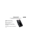
APPLICATION NOTE 311 MOTION SENSOR BASED ON ENOCEAN STM 300/400 1. Purpose of this application note Purpose of this Application Note is to show how to build a maintenance free, ambient light powered radio motion sensor based on the EnOcean Dolphin core devices. The demo concept implements the following function: a lamp is manually switched on when entering the room and remains on as long as a presence is detected in the room; finally, the lamp automatically switches off within a certain time after the room is vacated. The use of the multipurpose STM 300/400 enables simplified hardware due to its customer programmability. 2. Motion Sensor System Description The system consists of two modules, both EnOcean based: a) Light powered motion sensor as radio transmitter and b) Line-powered radio controller with switching actuator (and “Lamp ON” push-button). Fig. 1: Ambient light powered Motion Sensor Fig. 2: STM based Motion sensor (front view) Fig. 3: Line powered TCM based radio controller 3. Principle After pressing the “Lamp ON” pushbutton at the controller (Fig. 3) its integrated timer automatically switches the light on for a certain adjustable time length, i.e. for 5 minutes, like a timer switch for staircase lighting. The controller expects further presence messages in this time period. This time is sufficient for charging the empty energy storage capacitor of the ambient light powered motion sensor via its solar panel, thereby ensuring its start up and long-term function (cyclically transmitting presence messages when motion detected). The transmitter is an EnOcean STM 300/400 device that, in the case of a motion arising, sends a radio telegram at customer set time intervals, (only “presence” messages type “Lamp ON”). Therefore, each time a “Lamp ON” message from the radio motion sensor is received within this time period, the controller timer will be re-triggered and the “Lamp ON” time subsequently re-initialized for a new period of i.e. 5 minutes. Thus, the lamp remains ON for next 5 minutes and stays switched on as long as further presence messages are received in this time period. The controller SW implemented re-triggerable controller timer therefore functions as “missing pulse detector” for Lamp ON messages: i.e. if no message is received within this preset time period, the controller will automatically switch the lamp off at the end of that time period. Once the lamp is switched off, it can be automatically switched back on by a detection radio telegram within the next 30 seconds only. Thereafter it can only be switched on by manually pressing the on-button on the controller again. This concept means © EnOcean | www.enocean.com Subject to modifications | Christian Bach | Sep. 2015 | Page 1/ 6 APPLICATION NOTE 311 MOTION SENSOR BASED ON ENOCEAN STM 300/400 that the lamp is always switched off automatically by the controller, either after a maximum of e.g. 5 minutes (programmable time) after the room was vacated or if a fault arises (radio link broken) independent of room vacation. Additional master (“override”) EnOcean radio switches can be also implemented. The practical realization of such an EnOcean, i.e. TCM device based controller (actuator) is simple and therefore needs no further explanation here. 4. System Requirements for the Motion Sensor Demo Minimum working environment light level at the solar cell shall be 50 lx. Please note: on the ceiling you may have only about one tenth of the illumination measured on the desk! Charge time (start up) for the energy storage capacitor shall not exceed 5 minutes in the lowest specified illumination environment. Otherwise stated, this time is the charge up latency time from when the lights are manually turned ON after the room was in total darkness. Motion sensor shall transmit motion information to the wall box receiver i.e. once every 75 seconds. 5 minutes after the last received motion detection telegram (i.e. room is vacated) the light will be automatically turned off. The energy stored should be enough for next 30 seconds after the lights were turned off (totally darkness) to enable the transmitter to send a last “Lamp ON” telegram in case motion is detected within this time (auto re-activation period). 5. Block Diagram of the Motion Sensor Fig. 4: Block Diagram 6. Energy Balance Calculation The most important aspect of the dimensioning is to have lowest possible energy consumption. Since the energy is the product between current, voltage and time, this can be achieved in several ways: Design and build the sensor circuit itself as frugally as possible. A long time current consumption of about 5 µA (4 µA continuous + 1 µA averaged for transmissions) can be achieved using adequate components. Ultra low power electronic devices must be chosen. Therefore only “PIR” (passive) motion detectors types are suitable (driven by currents below 1 µA). A customer programmed STM 300/400 device periodically waked up through motion events will be used as transmitter. © EnOcean | www.enocean.com Subject to modifications | Christian Bach | Sep. 2015 | Page 2/ 6 APPLICATION NOTE 311 MOTION SENSOR BASED ON ENOCEAN STM 300/400 Consider 50 lx as worst case for the solar panel. Important considerations regarding energy management (i.e. solar panel dimension, ambient light conditions, transmitter power and number of transmissions/minute): In order to maintain the required nominal transmitted power P (i.e. range wide); the only place where “energy savings” can effectively be made is the time factor t (E = P x t). This means i.e. considering for a supply voltage of 3 V a transmission current consumption of 25 mA, makes a power consumption of 3 V x 25 mA = 75 mW. From this requirement results the transmission current averaged over time: A STM 300/400 radio telegram is only about 3/1000 second long, e.g. the average power when transmitting every second is reduced by a factor of 333, actually about 225 µW, e.g. 75 µA @3 V. This still seems to be a lot, but this power is what would be required if the transmission cycle were one time every second (W= V x A in 1 s). So if the number of messages will be limited i.e. to one telegram every 75 seconds, which is 75 times less current consumption again, i.e. 1 µA as long time “averaged” current by sending one message every 75 seconds. Energy storage capacity value requirements: Not too large so that a start up voltage of 2.6 V can be reached within i.e. 5 minutes after switching the light on @50 lx. This should ensure that the motion detector is operational within this time period. On the other side, the storage capacitor value shall be large enough to assure full recovery of the energy between two consecutive messages: i.e. maximal voltage drop on the storage capacitor < 0.3 V (i.e. from 3 V to 2.7 V) during one transmission to assure the full recovery between two transmissions and function of the sensor and also to work properly at least 30 seconds after the light is switched off (auto re-activation period). Important: please note that until the capacitors are charged to 2.6 V, correspondingly to the STM 300/400 start-up level, the motion detector circuit is NOT powered, so all the current generated by the solar panel, i.e. 5 µA is available for initial charging. The minimum needed storage capacitor value results using the formula C x U/2 = I x t: C > I x t x 2/U where I = 5 µA, t = 30 seconds, U = 2.6 V, so C > 120 µF needed for auto re-activation. C x 0.3 V/2 = 25 mA x 3 ms => C > 500 µF for a maximal voltage drop < 0.3 V To fulfill both conditions the greatest value has to be chosen, respectively C must be > 500 µF, let’s chose 680 µF. Since the typical tolerance of good tantalum capacitors in this range is ±20% in worst case the capacity will be at least 544 µF (680-20% µF). Finally the needed solar panel area results from the maximal current requirement: 5 µA average current at 3 V and initial charge time (start up) within 5 minutes (whichever current value is greater): C x U/2 = Ic x t, where C = capacity (µF), U = voltage (volt), Ic = charging current intensity (µA) and t = time (seconds) The charging current required for start up within 5 minutes is therefore in worst case: Ic (µA) = C x U/(2 x t) = (680 + 20%) µF x 3 V/(2 x 300 s) = 4 µA (< 5 µA) According thus, the minimum required supply current is 5 µA @50 lx. Since one transmission exhausts 3 ms x 25 mA = 75 µAs every 75 seconds while the charging current amount during this time is 1 µA (difference between the delivered current and the circuit current consumption without transmitting): 75 s x 1 µA = 75 µAs, meaning the recovery condition between two transmissions is also fulfilled. According to diverse data sheets for indoor solar cells (i.e. from Sinonar, Trony) a 2.5 cm2 large single solar cell is needed to generate the needed current @50 lx. © EnOcean | www.enocean.com Subject to modifications | Christian Bach | Sep. 2015 | Page 3/ 6 APPLICATION NOTE 311 MOTION SENSOR BASED ON ENOCEAN STM 300/400 Voltage considerations: the operating voltage of the chosen module should be selected so that the power point voltage is near the required operating voltage of the application. The required voltage of > 2.9 V @50 lx (due to an additional serial Schottky diode voltage drop), is assured by 8 serially connected single cells (according to the same data sheets). The last sentences give the following essential key data for the indoor solar panel: > 2.5 cm2 (single cell, current requirement) x 8 cells (voltage requirements), thus giving an effective solar panel area of > 20 cm2. One single Sinonar SS-5649 solar panel (8 cells, 27 cm2) would deliver the required power (7 µA @3 V). NOTE: solar cells work as a current generator and while the output voltage is only light dependent to the illumination over decades, the current varies direct proportional with the illumination and solar cell single area. Therefore the current dependence is linear while the delivered power is not quite linear (slightly reduced due to its voltage component and leakage currents influence at very low illuminations, as shown below): As rough, conservative estimation, indoors and for small area amorphous solar panels (few cm2) an operating current in the range of 10 µA/cm2 @200 lx (FL) can be considered. This value can be roughly linear extrapolated using a small derating factor for lower illuminations and / or smaller area. That corresponds i.e. to 4-5 µA/cm2 @100 lx. Additionally, amorphous cells deliver indoors nominal power densities of around 4 µW/cm2 @200 lx respectively < 2 µW/cm2 @100 lx. 7. Circuit Description and Implementation of a STM 300/400 based Motion Sensor The following described concept uses the integrated new features of the STM 300/400 (i.e. customer programmable, energy management facilities) and therefore is very simple. Hardware implemented functions (i.e. ultra low power timers or voltage supervisor used by the previous implementations) can be now software implemented. For details please consult the latest STM 300/400 user manual. After pressing the “Lamp ON” pushbutton at the controller, the controller turns the light on for a certain time, i.e. 5 minutes. The voltage generated by the solar panel will now rise slowly (due to the empty C3 and C4). At VDD >VON (about 2.5 V) the STM 300(C) starts up. This generates at the WXODIO (CCO) a “Hi” level that remains steadily high until VDD falls below VOFF (about 2 V). Thereby the motion sensor circuit will be only now continuously powered through the P-channel MOSFET. After every motion detection telegram the STM device wake input will be inhibited for the next 75 seconds to save energy. VDDLIM is used to protect the STM 300/400 by limiting its supply voltage to VDD < 5 V. The used motion sensor PIR1 is i.e. a miniature PIR sensor from Murata, IRS-B340ST02 (SMD, micro-motion detection, quad, Fig. 5). Its output signal is processed by the amplifiers LPV521 (Rail to Rail I/O, working voltage > 1.6 V, current consumption < 0.4 µA, from NS). Fig.5 Only the dynamic signal component (motion) will be filtered and amplified by about 80 dB. This amplified and filtered signal is added to a window comparator, realized with two MAX920 comparators (Nanopower, 1.8 V upwards, current drawn <0.4 µA, open-drain). Their outputs are connected as a logical wired OR gate through a common 1M8 resistor to UVDD (1.8 V). Therefore, the “high” WAKE input voltage level is kept at 1.8 V without using a limiter, despite the wide working voltage range (2…5 V) of the motion detector circuit. When a motion is detected the MAX920 output sinks to Lo and the STM device wakes up, sends a “Lamp ON” telegram and starts its internal i.e. 75 second inhibit timer. No further motion detection will lead now to a new wake up and radio transmission within the next 75 seconds. This time period can be flexible programmed into the STM device. © EnOcean | www.enocean.com Subject to modifications | Christian Bach | Sep. 2015 | Page 4/ 6 APPLICATION NOTE 311 MOTION SENSOR BASED ON ENOCEAN STM 300/400 Fig. 6: Realization example (simple HW principle) based on STM 300/400 8. Firmware example A very simple free firmware DEMO for this STM 300 demonstrator (called MotionSensor.ZIP, with a transmission cycle of only 5 seconds and EEP2.1 profile A5-07-01) is also provided into attachment for STM 300 DA modules only as example (“as is”, without any liability). To use this Firmware following tools/steps are needed: Following current tools are required: o Keil C51 compiler o DolphinAPI o DolphinStudio o DolphinView o MotionSensor FW © EnOcean | www.enocean.com Subject to modifications | Christian Bach | Sep. 2015 | Page 5/ 6 APPLICATION NOTE 311 MOTION SENSOR BASED ON ENOCEAN STM 300/400 Compile the Firmware (or use the precompiled hex file from the Output Folder) Using DolphinStudio program first the STM device Start DolphinView and press the learn button on the board. The sensor identifies itself automatically transmitting its EEP in the LRN telegram, see screen shot below. Monitor the motion detection using the EEP View as showed below. Fig. 7: DolphinView monitoring data from Motion Sensor Demo Disclaimer The information provided in this document describes typical features of the EnOcean radio system and should not be misunderstood as specified operating characteristics. No liability is assumed for errors and / or omissions. We reserve the right to make changes without prior notice. For the latest documentation visit the EnOcean website at www.enocean.com. © EnOcean | www.enocean.com Subject to modifications | Christian Bach | Sep. 2015 | Page 6/ 6