1
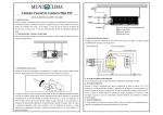
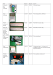
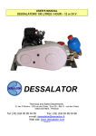
2. How to install the desalinator: 2.2 Motor unit: The HP motor unit should be installed as low as possible in the boat in a horizontal position and it must be protected from water spray as much as possible. The unit is mounted using two brackets under the two motors leaving a few centimetres clear space around the unit, to get sufficient air circulation space for 1 motor cooling. The connection between the prefilter oulet and 2 the inlet to the low pressure side of the pump is in Tricoflex hose of 12mm with doubled stainless jubilee clips at each joint. 3 The HP head of the pump is connected to the membrane inlet (red mark) through an HP pipe, cut to the appropriate length (see installation of connectors appendix A2). Apply a little liquid Loctite or nut seal on the male and female cones before joining. 1 2 3 2.3 Electrical connections: Negative battery cable Positive battery cable. Please connect a fuse holder to this cable. CAUTION: POWER SUPPLY SHOULD BE SWITCHED OFF BEFORE WORK IS CARRIED OUT. When connecting the 12 or 24V motor ensure that the polarity is correct: positive (brown wire) on the relay and negative (green/yellow wire) on the 12 or 24V motor. Depending on the voltage install a 12V fuse holder (supplied) or a 24V circuit breaker (supplied) on the positive cable. Ensure that the cable is of sufficient diameter: 35mm² for the 12V or 20mm² for the 24V. The Dessalator control cable is 5m long and is equipped with a plug with a pin locator system. The Dessalator® can only be operated when the power cable is connected to a DC supply. - Page 3 -