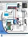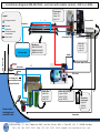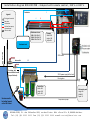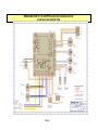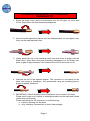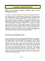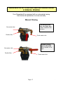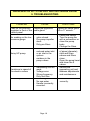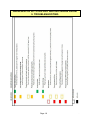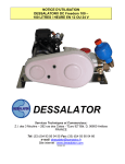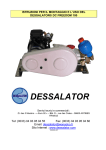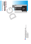
1
USER’S MANUAL INSTALLATION OF A DESSALATOR 90 TO 200 PRO IN 230 OR 400 V with mini remote control Mini remote control REMOTE CONTROL VERSION COMPACT VERSION DESSALATOR Technical and Sales Departments: Z.I des 3 Moulins – « Euro 92 » – Bât. D – rue des Cistes – 06600 ANTIBES Tel: (33) (0)4 93 95 04 55 Fax: (33) (0)4 93 95 04 66 e-mail: [email protected] Web site: www.dessalator.com Version A5 CONTENTS 1. Installation diagrams: Remote control – Horizontal version Remote control – Vertical version Integrated control – Compact version 2. Components supplied by DESSALATOR page 2 3. Installation Instructions: 3.1 Sea water inlet valve and filters 3.2 Pre-pump and high pressure switch 3.3 Membranes 3.4 Control panels 3.5 Motor unit 3.6 Connection plan page page page page page page 3 4 5 6 7 8 DES230N Wiring PRO 08052014.pdsprj 22-6-2014 VAK REV: A 3.7 High pressure connectors page 9 4. Instructions for use: page 10 5. Reverse osmosis principle 5.1 The membranes page 11 page 12 6. Maintenance: 6.1 Maintaining and 6.2 rinsing the membranes 6.2 Rinsing the membranes 6.3 Sterilizing the membranes 6.4 HP Pump page 13 page 14 page 15 page 15 7. Instructions for sterilisation of cartridges page 16 8. Manual Rinsing page 17 9. Troubleshooting 9. Troubleshooting: Led indicator page 18 page 19 I n s t a l l a t i o n d i a g r a m D 9 0 - 2 0 0 P R O - H o r i z o n t a l w i t h r e m o t e c o n t r o l , 2 3 0 V o r 4 0 0 V. Production 3 Legend: 1 Rinsing valve control Sea water Fresh water HP hose from pump to membranes Electric cable 8 6 Pressure switch Control panel: Width 220 Height 430 Depth: 120 Membranes D90: 1200x100x120 D160: 1200x190x120 D200: 1200x270x120 Fresh water tank Electric box: Width: 180 Height: 160 Depth:260 Sea waterline Capillar 230V power supply of the boat 4 Waste oulet 12 230 V motor For rinsing with pressurized fresh water (Pump of the boat). 1 Double filter Width: 360 Height: 360 Depth: 180 Strainers need to be looking forward on the hull of boat Motor unit – 90, 160 / 200 Length: 460/550 Width: 330/330 Height: 300/300 Mini remote control panel: Height:145 Width:80 Depth: 22 Low pressure DESSALATOR, Z.I. des 3 Moulins-282, rue des Cistes- Bât. « Euro 92 » D, F -06600 Antibes . Tel: (33) (0)4 93 95 04 55 Fax: (33) (0)4 93 95 04 66 e-mail: [email protected] I n s t a l l a t i o n d i a g r a m D 9 0 - 2 0 0 P R O - v e r t i c a l w i t h r e m o t e c o n t r o l , 2 3 0 V o r 4 0 0 V. Legend: 1 6 Rinsing valve control 8 Control panel Width: 220 Height: 430 Depth: 120 Pressure switch Production 3 Sea water Fresh water HP hose from pump to membranes electric cable Multiconductor Control panel 230V Sea waterline Electric box Width: 180 Height: 160 Depth: 260 Membranes: D90: 1200x100x120 D160: 1200x190x120 D200: 1200x270x120 Fresh water tank Capillar 4 Waste outlet Production valve 230 V power supply of the boat 12 230 V motor For rinsing with pressurized fresh water (Pump of the boat). Double filter: Width: 360 Height: 360 Depth: 180 Strainers need to be looking forward on the hull of boat 1 Motor unit 90, 160/200 Length: 460/550 Width: 330/330 Height: 300/300 Mini remote control panel: Height:145 Width:80 Depth: 22 Low pressure DESSALATOR, Z.I. des 3 Moulins-282, rue des Cistes- Bât. « Euro 92 » D, F - 06600 Antibes . Tel: (33) (0)4 93 95 04 55 Fax: (33) (0)4 93 95 04 66 e-mail: [email protected] I n s t a l l a t i o n d i a g r a m D 9 0 - 2 0 0 P R O - C o m p a c t w i t h r e m o t e c o n t r o l , 2 3 0 V o r 4 0 0 V. Production Legend: 1 3 6 Rinsing valve control Sea water Fresh water Hp hose from pump to membranes Electric cable 8 Membranes in mm D90: 1200x100x120 D160: 1200x190x120 D200: 1200x270x120 Compact Width: 580 Height: 380 Depth:480 Sea waterline Fresh water tank 230V motor Waste outlet 12 For rinsing with pressurized fresh water (Pump of the boat). 230 V power supply of the boat Rinsing valve Double filter Width: 360 Height: 360 Depth: 180 Strainers need to be looking forward on the hull of boat 1 Mini control panel: Height:145 Width:80 Depth: 22 Low pressure pump DESSALATOR, Z.I. des 3 Moulins-282, rue des Cistes- Bât. « Euro 92 » D, 06600 Antibes . Tel: (33) (0)4 93 95 04 55 Fax: (33) (0)4 93 95 04 66 e-mail: [email protected] 2. COMPONENTS SUPPLIED ACCORDING TO WATERMAKER TYPE: Version A5 Hull valve: The ¾ hull valve strainer filters out the larger particles at system entrance. Pre-pump: Fixed under the waterline it enables water to flow through the prefilters to the HP motor unit. For a manual rinsing or following to the filter replacement, please put the valve handle to the right and fill the circuit with fresh water during 3 or 4 minutes, then put the valve handle back to the bottom. Pre-filters (One filter for “solo” model): The first 25µm cartridge filters out rough particles and the second 5µm cartridge refines the treatment. For automatic rinsing an electrovalve is mounted. Motor unit: HP motor unit either in compact frame or with remote control. It allows water to be pressurised to 60-65 bars. Compact Version: Remote control version: Motor with integrated control Motor and control panel are separated Control panel: The control panel is either part of frame (compact version) or separated (horizontal or vertical version) and it manages the functions of the desalinator. Vertical version Compact version Page 2 Horizontal version . DESALINATOR 90 TO 200 PRO with mini remote control 3.1 INSTALLATION INSTRUCTIONS Sea water inlet valve1 ¾: 2 1 The sea water inlet valve should be positioned as low as possible below the waterline and should be accessible. The grooves on the strainer should be facing forward (towards the bow) for maximum water intake when the boat is moving forward. The underwater installation should be sealed with Rubson or Sicaflex. The valve and the hose connector can be installed using a tube made watertight with 577 loctite or PTFE. The sea water inlet valve should be connected to the pre-filter using a Tricoflex hose 19 mm inner diameter, with 2 stainless jubilee clips at each joint, with their tightening heads positioned diametrically opposite, on the hose. The hull penetration drilling diameter must be 27mm. Recommendation: ensure that the immersed part of the valve is painted with underwater grade paint. Bronze pre-filter - pre-filter directly fixed to the hull inlet valve2, Cartridge pre-filter: There are two parts to the cartridge prefilter. In order to allow the filter cartridges to be removed, 5cm space should be left below the pre-filters. A key is supplied to dismantle the filters. Anchoring clip is reversible. An electro valve is mounted on the outlet for automatic rinsing (Ø 15). Rinsing valve Recommendation: When replacing the pre-filter cartridge, be careful not to position the pre-filters above water-sensitive parts, for risk of them getting wet. Check that the O-ring seal for the basin is secure and that the bleeder screw is tightened. Page 3 . DESALINATOR 90 TO 200 PRO with mini remote control 3.2 INSTALLATION INSTRUCTIONS Pre-pump: 3 The pre-pump with its rinse valve3 (with exception of “Solo” version) should be installed as low as possible in the boat and should be easily accessible. The pressurised fresh water pipe should be connected to the valve to facilitate rinsing the desalinator. See water (at the beginning ot the manual) and electricity connection plan enclosed (page 8). Recommendation: Remember to attach two stainless jubilee clips to each joint. THE PUMP SHOULD NOT BE PLACED WHERE THERE IS A RISK OF WATER SPRAY. Compact version and horizontal version Vertical version Location of the fuse for the low pressure pump Pump cable case 230V Pump cable case 400V phase Earth neutral earth CAUTION: POWER SUPPLY SHOULD BE SWITCHED OFF BEFORE WORK IS CARRIED OUT. Page 4 . DESALINATOR 90 TO 200 PRO with mini remote control 3.3 INSTALLATION INSTRUCTIONS Membrane(s) according to desired water flow: 1 membrane for 90 litres / hour water production (1200 x 100 x 120mm) 2 membranes for 160 litres / hour water production (1200 x 190 x 120mm) 3 membranes for 200 litres / hour water production (1200 x 270 x 120mm) The membranes can be installed horizontally, preferably flat or on a wall support. They are mounted using 4 Parker screws in stainless steel brackets1. The number of membranes used depends on the desired water flow. Hose from the HP pump should join the membranes at the red ring2. As the hose from the HP pump vibrates, it is preferable that it is installed using an insulating pipe3. The HP connectors should be installed strictly in accordance with the connection plan (see page 9). Please apply a little Loctite or nut seal on the two male and female cones, before tightening. 2 1 3 Recommendation: To facilitate the attachment to the HP stainless steel joins 2, it is possible to rotate the heads through 90°, by unscrewing the grey production connectors. Remove the nut covers and loosen the 12 nuts maintaining the unit. Then remove the rod to obtain access, and rotate the membrane head using a box wrench to join the stainless steel connector. Reinstall the rod and tighten the unit. Page 5 . DESALINATOR 90 TO 200 PRO with mini remote control 3.4 INSTALLATION INSTRUCTIONS Control panels in accordance with your watermaker version: Vertical version: Front panel Back panel Horizontal Version: Front panel Back panel Compact version: Front panel Back panel Mini remote control All remote control panels must be mounted on a vertical surface. Installing the panels close to the watermaker system facilitates the piping and hose connections. Mini remote control: Optional extra which allows starting and shutting down the desalinator without using the general control panel. Figures for each connection are as follows: (see diagrams at the beginning of the manual) - N°8 (blue): HP piping exiting the membranes. - N°6 (blue hose 8/10mm diameter) production hose exiting the membranes. - N°3: Production hose from panel to tanks. A 10mm inner diameter Tricoflex length will be required which should be connected either to the fresh water tanks or to the fresh water pump provided there is no constricting valve on the fresh water tank outlet. - N°12: Waste outlet: 15mm inner diameter Tricoflex. - N°4: 4mm capillary hose (6m are provided) to be connected to the side of the HP pump and to the low pressure gauge. Page 6 . DESALINATOR 90 TO 200 PRO with mini remote control 3.5 INSTALLATION INSTRUCTIONS HP motor unit: There are three water connections to the pump head: - A 15mm diameter pipe1 from the pre-filters. - A HP hose2 to the 8mm diameter membranes (see installation diagrams pages 2, 3 and 4). - A capillary 3mm diameter tube3: this must be clipped into its connector. To remove it, just push the black ring and remove at the same time. The HP unit should be installed in a horizontal position and must be protected from water spray. Connections are illustrated below: 1 2 3 Phase Neutral Earth Additional hardware needed for assembly: - miscellaneous screws (including Parker) - assortment of stainless jubilee clips 10mm, 16mm and 19mm diameter - miscellaneous tie wraps - insulating piping 22mm diameter - Tricoflex hoses 10, 16 and 19mm diameter. Page 7 . DESALINATOR 90 TO 200 PRO with mini remote control 3.6 INSTALLATION INSTRUCTIONS Page 8 . Installation instructions – HP Connectors DESSALATOR 1. Screw the brass union (skirt) anti-clockwise onto the HP pipe, no more than 2.5cm. Stop where the inner threading disappears. 2. Insert the steel tapered end-piece into the stainless steel nut, and tighten very firmly on the male tapered union. 3. Lightly grease the tip of the stainless steel cone and screw it straight into the brass union. Stop where the steel threading disappears into the brass endpiece (a gap of approximately 7mm between the nut and the brass union) 4. Unscrew the nut of the tapered adaptor. The connector is now ready for the hose from pump to membrane. We recommend using an insulating pipe to protect it against vibrations. 5. IMPORTANT: Check carefully that the end-piece does not block the hose: - Please don’t forget to put Loctite or watertight product on the male and female cones when remounting. - Please check that the HP connector is not blocked up. a. either by blowing into the hose b. or by inserting a screwdriver to check free passage. Page 9 . DESALINATOR 90 TO 200 PRO with mini remote control 4. DIRECTIONS FOR USE 1. Ensure the valves are open before starting up the desalinator. 2. To be done compulsory: For the first use, after the replacement of the filter, when lifting the boat out of the water or for a long period of not using your water maker, please fill the circuit with fresh water: put the handle valve on the pre pump to the right; this operation should be done for 3 or 4 minutes, water maker stopped and pressure captor open (fully anti-clockwise). Once the circuit is full of fresh water put the valve handle on the low pressure pump back to the bottom. 3. To start the desalinator the first time, the pressure regulator must be open. Switch the interrupter of the main control panel on and give a quarter turn to impulse it: the low pressure pump will start than the high pressure pump will automatically start. 4. Turn the pressure regulator dial to the right, until the HP gauge reading is in the beginning of the green zone. Up from this operation, your watermaker can be stopped and started only with the mini remote control. 5. Fresh water quality and flow into the tank is automatically monitored by the electronics board. 6. If pressure becomes too high the desalinator will cut out and the red indicator will light up. If this occurs, reduce pressure and restart the desalinator. 7. To shut down the desalinator: Either use the mini remote control during the whole season, or, if you stop it for more than one month, reduce pressure on the main control panel and switch off: The rinsing electro-valve will be activated (see pages 13 and 14) Then proceed as described sections 3 and 4 of this page for a new use with the mini remote control. 8. To shut down the desalinator with rinsing, please see pages 13 and 14. 9. If the desalinator is not used for extended periods of time, it should be rinsed preferably once a month. If not, please remember to sterilize the membranes (with our special sterilization cartridge) for a storage valid for a period of max. 6 months. Note: Fresh water production depends on the temperature of the sea water and on the cleanliness of the pre-filters, together with the right voltage of the generating unit. Page 10 . DESALINATOR 90 TO 200 PRO with mini remote control 5. REVERSE OSMOSIS PRINCIPLE What is the reverse osmosis principle used in your desalinating system? Sea water is forced at high pressure through the membranes which act as “molecular sieves”, only allowing pure fresh water to pass through. Most dissolved solid particles will not penetrate the membranes. This waste, along with the remaining saline solution, will flow on the surface of the membranes and will be rejected. Not all particles dissolved in sea water can be eliminated. The system is designed to reject 99% of the TDS (Totally Dissolved Solids); approximately 2% of the 35,000 PPM/TDS will pass through the membranes. This guarantees drinking water with a TDS value of 500 (average). Please note that the drinking water produced by your reverse osmosis system is essentially sterile, however, your fresh water storage should be treated periodically with a slight dose of chlorine (or iodine) to ensure it remains consumable. Pay attention not to allow pure chlorine (or a too high dose of chlorine) into the desalination system, as this could damage the device. How does your desalinator work? Sea water enters the inlet valve which penetrates the hull. This sea water is then routed by the pre-pump through the 25 µm and 5 µm pre-filters. The filtered water is forced through the membrane by the HP pump (operating pressure 60 to 65 bars). The pressurized water passes through the surface holes of the membranes depositing the salt and minerals, which are then rejected into the sea with the remaining solution. The now fresh water flows over a detector which measures its salt content: If the desalination achieved is satisfactory, the three-way valve automatically directs the fresh water to the tank. If the salinity values measured by the salinity probe are too high (conductivity > 1,000 siemens), the valve will reject the water produced into the sea. The volume of drinking water being treated at any time is monitored by a flowmeter on the control panel. Page 11 . DESALINATOR 90 TO 200 PRO with mini remote control 5.1 REVERSE OSMOSIS PRINCIPLE MEMBRANES - DELICATE COMPONENTS Reverse osmosis membranes must be carefully maintained as they are the most delicate elements of the reverse osmosis system. We recommend that the maintenance instructions are carefully followed to prevent the membranes from damage and to ensure the guarantee is not invalidated. Maximum production capacity of the desalinator is achieved with a sea water temperature of 25°C. The functioning of the membranes will vary depending on the temperature of the sea water and on the sailing area. Output drops by approximately 2.5% to 5% for each degree below 25°C. Extreme temperatures: The membranes should not be exposed to temperatures below 0°C. Overpressure due to expansion caused by freezing can rupture the membranes and prevent the salt from being filtered out. The membranes must not be exposed to temperatures above 60°C, as high temperatures may also prevent salt from being removed. Drying out of the membranes: The membranes should be permanently immersed in liquid, either sea water before treatment, fresh water provisionally stored or sterilizing liquid, if the desalinator is not used for extended periods of time (Sterilizer is effective for six months and must be replaced after this period of time). Recommendations for use: The various quality and salinity grades of sea water affect both membrane efficiency and the working of the desalinator in Marinas. The system is not recommended for use in muddy or polluted water (briny water, river, Red Sea), which can clog and damage the membranes. However, if the desalinator has to be used in such conditions, only run it for very short periods and as soon as clean sea water becomes available rinse the membranes and run the system without pressure for 30 minutes with the pressure regulator open. Page 12 . DESALINATOR 90 TO 200 PRO with mini remote control 6. MAINTENANCE 6.1. Maintaining the membrane After 1,000 working hours, it is normal that the flow lowers between 10 and 15%. If more, you should think of replacing the membranes. The volume of production of your watermaker can be made over the first 24 to 48 hours of operation. If the drinking water produced falls below the normal working specifications (sea water containing a TDS of 35,000 ppm, a sea water temperature of 25°C, and pressure of 65 bars), and if production is not improved by rinsing the membrane, then the membrane has to be replaced. Please take into consideration that the volume of drinking water produced is dependent on ideal sea water temperature and on pressure in the system. Therefore, if the volume of drinking water produced falls it does not necessarily mean that the membrane need to be replaced. 6.2. Rinsing the membranes Once a week, the watermaker needs to be flushed with fresh water before using it to make fresh water. There is no need to flush it with fresh water after each use, as this is just a waste of water that is taken from the boat’s tank. There are 2 methods to flush the system: manual and automatic. Both systems are using the water that is in the tanks of the boat, and there is no use in water from the dock or a connection of any hose from a source outside the boat. Remember: The biggest enemy of the membranes is fresh water. Fresh water should be always used with no pressure when going through the system (pressure dial turned all the way anti clockwise) and the system should always run with no pressure after a fresh water flush to dump all the fresh water that are in it, before making freshwater from sea water (also with the pressure dial all the way anti clockwise). When running the watermaker with the dial all the way anti clockwise, it will shut it self down automatically after 1 minute. Only then, the watermaker is ready for use. Page 13 . 5. Maintenance: Manual Flush On the pre pump there is a valve. The valve is connected to the fresh water system of the boat and turning it, will automatically start the boat’s water pump and a flow of fresh water from the tank to the watermaker. 1. Don’t turn the watermaker ON. Leave it on it’s OFF position. 2. Turn the pressure dial all the way anti clockwise. 3. Turn the valve of the fresh water intake, which is located on the pre pump, for 2 minutes. The boat’s water pump will start and fresh water will run through the watermaker. Automatic Flush After using the watermaker, don’t switch it off. While the watermaker is still running, turn the pressure dial all the way anti clockwise. The watermaker will stop making water and will automatically start the flushing process. The green and orange lights on the control panel will turn on, which indicates that flushing is in process. This should take 30 seconds and will stop automatically. The green and orange lights will shut off and the only indicator will be the blue flashing light on the ON/OFF button, to remind you to shut the watermaker OFF. The automatic flush is a better way to flush the system since it’s not only flushes the sea water out, it also back wash the pre-filter and dumps all the dirt and debris that accumulated in the filter’s housing, back to the sea, through the sea water intake. DON’T FORGET!!! After each system flushing, before using the watermaker you need to: 1. Make sure the pressure dial is turned all the way anti clockwise. 2. Turn the watermaker ON and let it run with no pressure for 1 minute until the red alarm light comes on. This is the time needed for the sea water to replace all the fresh water that is in the system, before running pressurized sea water through the membranes. RUNNING FRESH WATER IN HIGH PRESSURE THROUGH THE MEMBRANES WILL DAMAGE THE MEMBRANES!!! Page 14 . DESALINATOR 90 TO 200 PRO with mini remote control 6. MAINTENANCE CAUTION: IN FREEZING CONDITIONS, PLEASE EMPTY THE FLOWMETER TUBE ON THE CONTROL PANEL BY DISCONNECTING THE PRODUCTION HOSE AND BLOWING OR INJECTING AIR INTO THE HOSE, PROTECT YOUR MEMBRANES WITH BLANKETS. 6.3 STERILIZING THE MEMBRANES When should the membranes be sterilized? Normally, regular monthly rinsing of the membranes may be all that is required to maintain the membranes. If this is not possible, sterilization will be necessary. Membrane sterilizing procedure: 1. Manual method: Thoroughly rinse the desalinator with fresh water for 10 minutes using the three-way valve on the low pressure pump. This procedure should be followed while the machine is idle. Pour the sterilizer (entire packet contents) into a bucket containing 8 litres of water. Disconnect the sea water inlet hose and immerse it in the bucket. Run the desalinator without increasing pressure until the bucket is empty. When the bucket is empty and the procedure is completed and the hose can be reconnected. If not, see number 3. 2. The sterilizing procedure can also be carried out using a garden spray: Pour the entire packet contents of sterilizer into a bucket containing 8 litres of fresh water and mix thoroughly. Fill the spray bottle with this mixture and spray the sterilizer into the watermaker valve opening inlet, at a spray pressure of around 3 to 4 bars. If not, see number 3. 3. Sterilizing cartridge ST2: We have developed a sterilizing cartridge which makes this procedure very simple and easy. Cartridge instructions are given on the next page. Before using the desalinator again simply rinse with fresh water for a few minutes using the three-way valve on the pre-pump and all traces of the sterilizer will be removed. 6.4 HP Pump The HP pump is half filled with oil to the indicated level. Normally it is done for 500 hours. If refilling is necessary, use multi grade oil 15W40 and do not exceed the indicated level (in the middle of the red mark on the gauge which is on the back of the pump to the opposite of the pump head). BEWARE: the sticker located on the red oil filling cap of the HP pump is there only for the shipment: it must be removed before use. Page 15 . 7. INSTRUCTIONS FOR STERILIZATION OF THE MEMBRANES WITH OUR ST CARTRIDGE 1. 2. 3. 4. 5. 6. 7. 8. Close the sea water inlet valve. Open the sterilizing cartridge Remove the top grid Place the foam filter at the bottom of the filter Pour the powder into the cartridge Replace the top grid and close the cartridge Check that the seal is properly positioned. Remove the 5μm cartridge from the pre-filter. Remove the 5μm cartridge from the 2nd pre-filter 9. Replace with the sterilizing cartridge Replace the 5μm cartridge (in the 2nd pre-filter) with the sterilizing cartridge. 10. Set the rinsing valve to pressurized fresh water and leave a little sterilizer in the filter. 11. Do not run the desalinator at this point. 12. The sterilization remains effective for six months at most. (Repeat after this time as necessary). IMPORTANT: Before next use, rinse the desalinator thoroughly with fresh water for 15 minutes. Ensure that the sterilizing cartridge has been removed and replaced by a 5 μm cartridge. BEWARE: The ST2 cartridge is reusable. Page 16 . DESALINATOR 90 TO 200 PRO with mini remote control 8. MANUAL RINSING Your Dessalator® is equipped with an automated rinsing. Here below the procedure to rinse manually. Manual Rinsing Normal position for sea water use : Sea water inlet Valve handle to the bottom. Double filter Fresh water inlet Manual rinsing and sterilization : Valve handle to the right. Sea water inlet Double filter Fresh water inlet Arrivée d’eau douce Arrivée d’eau douce Page 17 . DESALINATOR 90 TO 200 PRO with mini remote control 9. TROUBLESHOOTING PROBLEM CAUSE Leak on the pressure Loosened regulation regulator in front of the cable gland control panel No reading on the low pressure gauge - valve closed - Pre-pump impeller stuck - Dirty pre-filters - reduced water inlet or air inlet in the system. - residues in the pump valves. Noisy HP pump. - Generating unit too weak - Voltage error - Wrong frequency - Dirty fuel filter. - No rinsing - No sea water - Handle incorrectly mounted. Variations in speed of the electric motors Three-way valve SOLUTIONS Tighten the cable gland with a 17 wrench. - Check the valves - Turn the pump fan with a screwdriver or clean the pump body. - Change the filters. - Ensure correct size of pipes (diameter), clips and filters secure and filters clean. - Open the pump head and clean the 6 valves. - Service the generating unit and address adjustments and maintenance. Fix the handle correctly. - Page 18 . DESALINATOR 90 TO 200 PRO with mini remote control 9. TROUBLESHOOTING Page 19 .