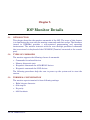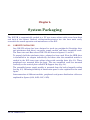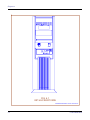
1
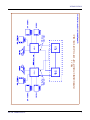
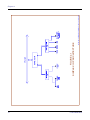
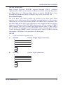
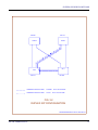
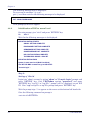
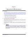
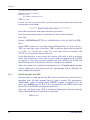
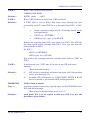
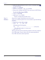
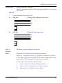
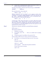
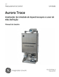
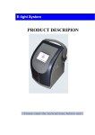
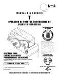
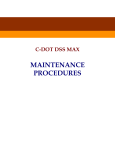
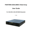
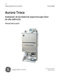
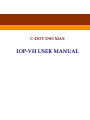
C-DOT DSS MAX
IOP-VH USER MANUAL
Section No. 400-027-0662
System
Practices
Draft 03, February1999
C-DOT DSS MAX
IOP-VH USER MANUAL
(This Document is updated for UNIX release 10.11)
© 1999, C-DOT
Printed in India
C-DOT DSS MAX
IOP-VH USER MANUAL
DRAFT 03
FEBRUARY 1999
MAGHA 2055
SERIES 000 : OVERVIEW
CSP SECTION NO. 400-027-0662
THIS C–DOT SYSTEM PRACTICE REFERS TO THE C–DOT DIGITAL SWITCHING SYSTEM
MAIN AUTOMATIC EXCHANGE (ABBREVIATED AS C-DOT DSS MAX IN THE REST OF THIS
PUBLICATION).
THE INFORMATION IN THIS SYSTEM PRACTICE IS FOR INFORMATION PURPOSES AND IS
SUBJECT TO CHANGE WITHOUT NOTICE.
A COMMENT FORM HAS BEEN INCLUDED AT THE END OF THIS PUBLICATION FOR
READER'S COMMENTS. IF THE FORM HAS BEEN USED, COMMENTS MAY BE ADDRESSED
TO THE DIRECTOR (SYSTEMS ), CENTRE FOR DEVELOPMENT OF TELEMATICS, 39, MAIN
PUSA ROAD, NEW DELHI - 110 005
© 1999 BY C–DOT, NEW DELHI.
Table of Contents
Chapter 1.
Chapter 2.
Chapter 3.
Chapter 4.
Chapter 5.
Chapter 6.
Chapter 7.
Introduction.............................................................................................................................. 5
1.1. General .............................................................................................................................. 5
1.2. Functions of IOP in DSS MAX ......................................................................................... 5
1.3. Interconnection of IOP with C-DOT DSS........................................................................ 6
System Overview (Hardware) ................................................................................................. 8
2.1. General .............................................................................................................................. 8
2.2. IOP-VH Hardware Architecture ...................................................................................... 8
2.3. IOP CPU (VHC) Card ....................................................................................................... 9
2.4. Misc. Hardware Details .................................................................................................... 9
System Overview Software.................................................................................................... 12
3.1. General ............................................................................................................................ 12
3.2. Structure of IOP Software .............................................................................................. 12
3.3. Duplex Operation ............................................................................................................ 14
3.4. IOP Monitor and Diagnostics ......................................................................................... 14
IOP Initialisation (S/W Loading) .......................................................................................... 16
4.1. General ............................................................................................................................ 16
4.2. Description of Initialisation Levels................................................................................ 16
4.3. IOP - Software Initialisation Procedures ...................................................................... 17
4.4. Loading Procedure .......................................................................................................... 18
IOP Monitor Details............................................................................................................... 27
5.1. Introduction..................................................................................................................... 27
5.2. Types of Commands ........................................................................................................ 27
5.3. Terminal Configuration.................................................................................................. 27
5.4. Function of Buttons & Keys ........................................................................................... 28
5.5. Command Descriptions................................................................................................... 28
System Packaging .................................................................................................................. 33
6.1. Cabinet Packaging .......................................................................................................... 33
Operation & Maintenance ..................................................................................................... 43
7.1. General ............................................................................................................................ 43
7.2. IOP initialisation Procedure .......................................................................................... 43
7.3. Shut Down Procedure ..................................................................................................... 45
7.4. Accidental Abort/Reset ................................................................................................... 46
7.5. Maintenance Related Problems and Solutions ............................................................. 46
7.6. Procedure for Copying Unix Boot Cartridge ................................................................. 52
H:\HOME\MAX\WORD\IOPVHUSM.DOC
February 4, 1999
Chapter 1.
Introduction
1.1.
GENERAL
C-DOT IOP is used as front end processor in C-DOT DSS MAX. It communicates
with DSS MAX on high speed data links. It contains a fault tolerant software, a
layer above UNIX V.2, which ensures data consistency between DSS MAX and the
IOP. Keeping the reliability considerations in view, two separate IOPs work in
duplex configuration.
1.2.
FUNCTIONS OF IOP IN DSS MAX
IOP basically handles all the input and output functions in DSS MAX. All the
commands from operator are received and analysed by IOP. If it requires the help of
Administrative Processor (AP)/ Base Processor (BP) to answer, AP/BP is contacted
otherwise the answer is given to the user.
The major functions performed by C-DOT IOP in DSS MAX, are listed below in a
classified manner :
a)
Downloading and Initialisation of DSS MAX
The complete software of DSS MAX is kept in IOP as files. To initialise the
DSS MAX, code and data is downloaded from IOP to the Switch.
b)
Man-machine Interface
The man-machine interface on IOP performs the function of user interface
with the DSS MAX. There are two major categories of commands :
♦ Administration commands
♦ Maintenance commands
c)
Handling of Billing and Traffic Data
♦ The basic UNIX V.2 file management system is used to store this
information.
d)
Printing of Maintenance and Traffic Reports
IOP-VH USER MANUAL
5
Chapter 1
f)
Exchange Management Functions
IOP provides information related to exchange configuration and also helps in
dynamic reconfiguration.
1.3.
INTERCONNECTION OF IOP WITH C-DOT DSS
Figure 1.1 depicts the interconnection of IOP with the DSS MAX. The Input
Output Processor Module (IOM) consists of two similar racks called IOP-0
and IOP-1. Each rack houses assembled cards and the peripheral devices
viz.Hard Disk, Floppy Drive and Cartridge Tape Drive.
The IOP communicates with the Switch through HDLC link. The two IOPs
communicate with each other through another HDLC link.
When both the IOPs are working, one acts as the master and other as the
slave. All the messages of the slave IOP to AP/BP are routed through the
master. However, backup devices like winchester are updated in both the
IOPs, i.e. whenever an updation is performed on its winchester, the master
will send a message to the slave IOP to perform a similar updation on
winchester of slave IOP. This helps in maintaing two copies of back-ups in
two different IOPs to ensure smooth operation of the exchange even in case of
total failure of one of the IOPs.
!
WARNING
Proper shutdown procedure should be followed to avoid corruption
of file system. Always use INIT-IOP:2,1; command. Also make the IOP
out of service using the command INIT-IOP: 2,1; The command
FRC/PUT-SWU-OOS should be used only when IOP in being
synchronised.
6
C-DOT DSS MAX
FIG. 1.1
INTERCONNECTION OF IOP WITH C-DOT DSS MAX
INTRODUCTION
IOP-VH USER MANUAL
7
Chapter 2.
System Overview (Hardware)
2.1.
GENERAL
The Input Output Processor (IOP) is a general purpose computer running UNIX
and is used as the front end processor in C-DOT DSS. It handles all the input and
output functions in C-DOT DSS. The IOP is connected to AP/BP via HDLC links.
During normal operation, two IOPs, interconnected by a HDLC link, operate in a
duplex configuration. Working as front end processor, it provides the initial code
down load to the subsystems, the man machine interface and the data storage for
the billing and other administrative information.
2.2.
IOP-VH HARDWARE ARCHITECTURE
The IOP-VH is defined as Value engineered High performance IOP-excelling the
performance of all the existing versions at a cost performance advantage. It is
designed on a single card named VHC. Figure 2.1 depicts the simplex IOP-VH
architecture. IOP does not follow the standard duplication strategy of the rest of
DSS. The IOP card is not duplicated, but the IOP as a module is duplicated.
The system has provision for 7 HDLC channels. Two of these are used to connect
the IOP to both the copies of AP/BP. The third link is for connection with mate IOP
when the two are working in synchronisation in duplex IOP configuration. The rest
four links will be used toward the four CMS in future.
Eight channels of RS-232C Serial Links (through ASIO ports) are also implemented
for connecting operator terminals and printer to the IOP in addition to two ports for
console and host.
The monitor based maintenance operations could be performed only from the
console. It is possible to login to ‘root’ account from console only and hence
operations like system boot-up, software link loading etc. could be performed only
from the console. The provision for one x.25 port is also there which can be used for
64kbps full duplex link via modem (for communication with Telecom Management
Network) with synchronous RS232 support at physical level influence. In addition
another provision for one 10 Mbps Ethernet port is also there in the IOP-VH which
has AUI or co-axial interface support at physical level which can be used in future.
8
C-DOT DSS MAX
SYSTEM OVERVIEW (HARDWARE)
The ETHERNET port is aimed to allow networking of terminals in future. It will
also aid in the implementation of graphics support in future.
A SCSI-2 controller with integrated DMA and SCSI cores is used for interfacing the
disk drive, cartridge tape drive and the floppy drive.
The VH-IOP functions are implemented on a single (VHC) card.
Note :
Presently the two ports, namely X.25 and ethernet ports are not supported.
2.3.
IOP CPU (VHC) CARD
The IOP CPU uses 68040 (25 MHz) processor and is housed on the VHC card. It has
16 MB (expandable to 32 MB) DRAM onboard and 512 KB EPROM. All active IOP
processes reside in the dynamic RAM and hence the data coming from/going to
HDLC links, secondary storage devices and terminals use the dynamic RAM.
2.4.
MISC. HARDWARE DETAILS
In addition to above CPU card, two more assembled PCBs are used to support
additional functions which are listed below :
i)
FFD Card : This card is used to generate fan failure signal which is
extended to OMA through FBI logic. Whenever the fan is stopped, alarm is
extended to OMA to draw the attention of maintenance staff.
ii)
VH-IOP Interface Card (VHI) :. This card is used to terminate
1.
Eight 9-pin D type connectors for ASIO which will support modem.
2.
Seven 25-pin D type connectors for HDLC.
*3.
One 25-pin D-type connector for X.25 over RS-232 interface.
*4.
One 15-pin D-type connector for Ethernet (AUI)
*5.
One BNC connector for cheapernet.
*
These are not supported presently.
IOP-VH USER MANUAL
9
10
LOTUS\VOL1\DESIGN\DSSMAX\MAX-L\IOPVH-UM\IVUM-IA
FIGURE 2.1
SIMPLEX IOP ARCHITECTURE
Chapter 2
C-DOT DSS MAX
SYSTEM OVERVIEW (HARDWARE)
IOP-VH Peripherals :
Input Output Processor (IOP-VH) supports standard SCSI-2
interface,
implemented on VHC card to interface to Winchester Drive, Cartridge Tape Drive
and Floppy drive (3½”). However, floppy drive is not used in IOP-VH. Here, it may
be noted that peripherals with SCSI-interface only can be used in IOP-VH.
Front Panel Display
The CPU ‘Reset’ and ‘Abort’ switches are provided at the front panel. These
switches can be locked using the lock and key provided adjacent to the switches.
(When the key is in the lock position, RESET and ABORT will be inhibited). ‘Run’
and ‘Halt’ LEDs for the CPU status indication is also extended on the front pannel.
Continuous flickering of the RUN LED indicates that CPU is running. If HALT
LED is glowing, then CPU is halted. Apart from these two LEDs, a ‘Reset’ LED is
also provided. This is mounted alongwith RESET switch and glows when the CPU
is reset by pressing ‘RESET’ switch on the front panel. Power I/P LED to indicate
the presence of I/P power is also provided on the front panel.
IOP-VH
1.
Cable connections for printer cable
a)
IOP side
2
3
8
5
1
4
6
Printer (25 pin D-type connector)
2
3
20
7
b)
IOP side
2
8
3
5
1
4
6
Printer (6 pin connector)
1
2
3
5
IOP-VH USER MANUAL
11
Chapter 3.
System Overview Software
3.1.
GENERAL
C-DOT IOP runs on the UNIX V.2 operating system. UNIX provides multi-user
environment for DSS MAX application software. One part of this application
software (Viz., the processes 'crp' and 'orp') implements the Man-Machine Interface,
which makes the exchange operator transparent to the operating system. For
detailed description of 'crp' and 'orp' commands refer to the documents
Administration Command and Maintenance Commands. Only the exchange
administrator, who is incharge of maintenance of the exchange and IOPs has to
interact with UNIX, and every effort is made to reduce even this to a minimum.
Since the IOP needs certain standard procedure to be followed for boot up, shut
down or bringing in duplex, some amount of operator interaction with UNIX will be
necessary.
3.2.
STRUCTURE OF IOP SOFTWARE
IOP software is structured as a layer above UNIX and is composed of the following
(Ref. Fig. 3.1):
a)
Command Interpretation Layer
A topmost layer like shell, to take operator commands, validate them, and
execute them.
b)
Administration Software
A layer above UNIX which provides the man-machine interface.
c)
Maintenance Software
Used for initialising communication protocol with DSS MAX. It also provides
software for synchronisation of IOPs.
12
C-DOT DSS MAX
SYSTEM OVERVIEW SOFTWARE
FIG. 2.1
IOP SOFTWARE ARCHITECTURE
(BASED ON UNIX MODEL)
IOP-VH USER MANUAL
13
Chapter 3.
d)
Communication Software
Used for providing Connectivity to DSS MAX and Telecom Management
Centre (TMC).
The functions of IOP software subsystem in DSS MAX are downloading and
initialisation, performance measurement of the processes, provision of man
machine interface and billing, traffic and maintenance reports, etc.
3.3.
DUPLEX OPERATION
As mentioned earlier, cards in IOP are not duplicated, but IOP as a module is
duplicated. In a duplex IOP configuration Fig. 3.2, one of the IOPs will be in INSACT (in-service active) state and the other will be INS-SBY (in-service standby)
state. Though both IOPs in a duplex configuration are physically connected to both
the APs/BPs through HDLC links, only INS-ACT IOP will be able to communicate
to INS-ACT AP/BP. But all updations which are occurring on the INS-ACT IOP will
be performed on the INS-SBY IOP also. This is done by the INS-ACT IOP through
the IOP to IOP HDLC link. The operator commands which are initiated from the
INS-SBY IOP get routed through the INS-ACT IOP to AP/BP, if the command
requires communication with AP/BP.
3.4.
IOP MONITOR AND DIAGNOSTICS
On power-on a prompt 'VHC x.x' will be displayed on the console VDU, where x.x is
the monitor program version number. The IOP cannot be accessed from terminals
other than the console at this time. This program resides in the monitor PROMs on
the IOP CPU card. Many diagnostic commands are available at this level for testing
the various devices. These commands are described in Chapter 5 of this manual.
14
C-DOT DSS MAX
SYSTEM OVERVIEW SOFTWARE
INS-SBY
INS-ACT
AP/BP-0
AP/BP-1
IOP-1
IOP-0
INS-SBY
INS-ACT
COMMUNICATION PATH FROM
STANDBY
COMMUNICATION PATH FROM
ACTIVE
IOP TO ACTIVE AP/BP
IOP TO ACTIVE AP/BP
FIG. 3.2
DUPLEX IOP CONFIGURATION
\DESIGN\DSSMAX\MAX-L\IOPVH-UM\IVUM-ACT
IOP-VH USER MANUAL
15
Chapter 4.
IOP Initialisation (S/W Loading)
4.1.
GENERAL
IOP can operate at various levels of initialisation. These are called the different 'run
levels'. Activities which IOP can perform are limited to the current IOP
initialisation level. The IOP run level should not be confused with the IOP status,
they are different. The following run levels are possible:
4.2.
•
Power Off
•
Cold Start
•
Warm Start
•
DIS-UPD-ALL (Disable Update All)
•
DIS-UPD-OPR (Disable Update Operator)
•
INS-ACT or INS-SBY (Inservice active or Inservice standby)
DESCRIPTION OF INITIALISATION LEVELS
A brief description of the different run levels are given below :
4.2.1.
Power Off
When the power to IOP is off, IOP is in 'Power Off level.
4.2.2.
Cold Start
On Power on the IOP, it comes to Cold Start level and displays the monitor
prompt 'VHC x.x >' on the console. At this level operator can choose to work
with the monitor (say, running diagnostics etc.) or go to the next level (i.e.
Warm Start).
4.2.3.
Warm Start
This level is reached when IOP is booted up (IOP booting up procedure is
described later.) by giving 'bo' command from the monitor. The IOP is
initialised and the DSS software starts running, “Console login” will appear
on CONSOLE terminal & “login:” prompt appears on all the other configured
16
C-DOT DSS MAX
IOP INITIALISATION (S/W LOADING)
terminals. The shell prompt i.e. IOP5C> or IOP5D> is displayed after the
operator performs login. At this stage IOP does not have communication with
AP/BP.
4.2.4.
Disable Update All
The 'crp' command 'init-iop' can be used to bring IOP to this level. This level
is between 'Inservice' and 'Warm Start'. AP/BP communication with IOP will
be through, but no updations from operator and subscriber initiated features
will be allowed.
4.2.5.
Disable Update Operator
The 'INIT-IOP' command can be used to bring IOP to this level. This level is
between 'Inservice' and 'Disable Update All' levels. At this stage AP/BP
communication with IOP is through and all other updations other than
operator initiated updations are possible. IOP might come to this level
automatically from 'inservice' level if overload (i.e., if the IOP CPU Idle time
falls below threshold) occurs. In such cases IOP will return automatically to
'inservice' level when overload condition is restored to normal.
4.2.6.
INS-ACT or INS-SBY (Inservice active or standby)
This run level is reached through 'init-iop' command. At this stage all
commands and updations are allowed and AP/BP communication is also
through.
4.3.
IOP - SOFTWARE INITIALISATION PROCEDURES
This section describes the software initialisation procedure for the IOP i.e., the
copying of exchange software on to IOP disks and initialising IOP.
Before starting the installation procedure make sure that you have the following
deliverables.
4.3.1.
UNIX Cartridge
This cartridge contains the boot block, UNIX kernel, standard UNIX utilities
and protocol software. This cartridge performs functionality of both minload
and UNIX cartridge. Hence minload floppy is no longer required with this
UNIX cartridge.
4.3.2.
Base (Link) Cartridge (BAC)
This cartridge contains different software modules which are down loaded to
switch units at the time of system initialisation. This is the base link over
which patches, if any, are installed.
IOP-VH USER MANUAL
17
Chapter 4.
4.3.3.
Combined Patch (Link) Cartridge (CPC)
This cartridge contains different patches for AP/BP/SSC and IOP. The
patches of this cartridge gets installed and patched to different S/W modules
automatically.
4.3.4.
Bare Minimum Data Cartridge (BMDC)
This cartridge contains bare minimum data, required to initialise the
exchange. The site specific exchange data is created after loading of BMDC.
4.4.
LOADING PROCEDURE
Software installation should be done carefully following the steps listed below. All
cartridges in the deliverables provided are write protected. Do not remove write
protection unless mentioned explicitly in the procedure. Read through the
procedure completely and ensure that you have understood the procedure
thoroughly before attempting software initialisation.
4.4.1.
Software Loading Procedure
The software can be installed by following the steps given below. The job can
be aborted at any time by hitting DEL key on the IOP console. All the
cartridges are write protected. DO NOT REMOVE WRITE PROTECTION
unless mentioned explicitly in the procedure. Read through the entire
procedure to make sure that you understand the procedure completely before
entering any command.
Step 1:
Loading of UNIX Cartridge
For IOP-VH make sure that card is inside IOP cabinet. Power ON the IOP by
switching on from the back panel.
On the console following is displayed when the IOP-VH is powered ON.
18
C-DOT DSS MAX
IOP INITIALISATION (S/W LOADING)
ACIA Rx Test Ttype character – “a”
Type the character “a” here. On typing a following printers will be displayed.
Abort flag status : cleared
Reset was due to Power On.
Version ID : 0
HEALTH TEST COMPLETE PLEASE CHECK RUN LED
Press any key to continue:
Now press the return key. On pressing Return key, following message will be displayed.
Power On Configuration .... PRESENT ABSENT
VHC
:
IMP0
IMP1 IMP2 IMP3 IMP4 IMP5 RTC
SCSI :
SCSI DMA
On board Memory Size :
1000000H to 1FFFFFFH
DEVICE
NCRNO
ID
DEF
MODEL NO
CART
0
2
c
TAN DBERG TDC 3600 = 08 :WINCH
0
6
W0
QUANTUM MAVERICK 5405 0905
VHC MONITOR© CDOT
M68040 VERSION X.X FEB’ YY
VHC x.y>
represents the type of IOP and monitor version running on the IOP.
Insert the UNIX cartridge in the cartridge drive and input the following
command on monitor prompt.
VHC x.y> bo
c
vh x.y
System starts loading of files with various prints appearing on the screen.
Wait for the message :
For IOP-ML or IOP-VE or IOP-XLE or IOP-TMC or IOP-VH
(m / v / e / t /h) ?
Now input your choice as h for IOP-VH and wait for the message (for other
IOPs, give corresponding options). The system then displays the system type
and the device configuration on which the root file system is to be made. Wait
for the display message :
Want to format the winch (s) (y or n)?
!
WARNING
In case of IOP-VH, only ‘n’ option should be used, as formatting of disk is
not required.
Now wait for following message.
winch capacity : 2063MB
Load the object (y/n) ?
IOP-VH USER MANUAL
19
Chapter 4.
The S/W loading operation will be aborted if ‘n’ is typed. If ‘y’ is typed the
system will display different messages showing the current activity,
Making ROOT file syste …m. over !
Transfering boot loader to root device …..
Loading the object …..
Single root file system found, positioning the cartridge.
Now the system will start copying from the UNIX cartridge. After the copy is
over, an audit is conducted. Immediately after audit, a file system check will
be performed automatically. After this the system will prompt with Root
File System Loading Complete ‘Hit Reset and Reboot from
Winchester’. Reset the system and boot-up the IOP by giving ‘bo’ command.
VHCx.y>bo
The following queries are displayed only for the first time when the IOP is
booted after unix loading.
Release 1_35_1_7(l3) or
2_1_1_1(l5) (l3 or l4 or l5) ?
1_4_1_3/1_4_1_4(l4)
or
1_5_1_1/1_5_1_2/
Select l5 for software release 2-1-1-1.
Load IOP SYSTEM (unix + Hdlc)
[1.1-96/01/30]
System ! cdix-vh with 2063MB
Loading release 1_5_1_1/1_5_1_2/2_1_1_1/2_2_1_1
ROOT File System Present
Create file systems other than root (y/n) ?
!
WARNING
If the exchange software data is already available and only UNIX is being
loaded, then give option ‘n’.
At the time of fresh installation, where the entire exchange software has to
be loaded, option ‘y’ is to be used for complete loading of software link. If ‘y’ is
given the system would keep indicating the file systems that it is creating.
Wait till the system displays (“over!”). Specify the date and time in the
specified format and proceed.
20
C-DOT DSS MAX
IOP INITIALISATION (S/W LOADING)
When booting is complete Console login : prompt will appear on the console.
If the ‘n’ option has been selected, subsequent steps 2,3 and 4 need not be
executed.
Step 2:
Loading of Base Cartridge
To do this, login into ‘root’ account. The password for the root just after the
UNIX cartridge installation is `DSSroot'. After successful login, UNIX version
will be displayed. And you will get #> prompt. Insert the exchange software
base cartridge into the cartridge drive and type the commands
#cd /usr/cdot <RETURN>
#RESBC <RETURN>
The following message will be displayed :
CARTRIDGE RESTORATION UTILITY
FOR
BASE CARTRIDGE
Starting......
Have you inserted cartridge ? (y/n)
Give `y' to load the base cartridge to winchester else give ’n’, abort the
operation.
It will start loading from cartridge onto disk. Note down the block size and
check with the blocks written on the base cartridge. After complete
restoration of files, the system will ask for the IOP ID.
Give IOP-ID (0/1) :
Give proper copy id of IOP. It is `0' for IOP with unit-id 5C> and ’1’ for IOP
5D>.
The system will audit the files on the disk by comparing it against a master
list and will display results followed by logging out, message.
IOP-VH USER MANUAL
21
Chapter 4.
After completion of successful audit, system will report the audit results as:
Audit Over !
Logging out...
Console login:
[If the audit gives some error, it concludes that the software installation is
not successful. It has to be installed again].
Step 3:
Loading of Patch Cartridge
This procedure is to load the AP/BP/IOP patches from the patch link cartridge to
the winchester disk. To do this, login into `root’ account. Password for ’root’ account
after software installation is ’DSSroot’. Insert the exchange software patch cartridge
into the cartridge drive. Give the command.
#cd /code/audit <RETURN>
#killall <RETURN> it should be given when only patch cartridge is to be loaded.
#RESPC <RETURN>
The following message will be displayed :
CARTRIDGE RESTORATION UTILITY
FOR
PATCH CARTRIDGE
Starting.....
Have you inserted cartridge ? (y/n)
Give ’y’ for loading the patches to winchester or give ’n’ to comeout.
All the patches required by the switch will be copied from the cartridge onto disk at
proper places. Look for the number of blocks displayed after loading of patch
cartridge is complete. Audit utility will also start automatically. Wait for audit to be
over. Remove the patch cartridge.
22
C-DOT DSS MAX
IOP INITIALISATION (S/W LOADING)
Step 4:
Loading of Bare Minimum Data Cartridge
Insert the data cartridge into the cartridge drive
Give the commands
#cd /code/audit <RETURN>
#RESDC <RETURN>
The following message will be displayed.
CARTRIDGE RESTORATION UTILITY
FOR
DATA CARTRIDGE
Starting......
Have you inserted cartridge ? (y/n)
Give `y' if you want to load the data cartridge to winchester else give ’n’ to
comeout.
The minimum office data files are loaded from the cartridge onto disk at proper
place. Check for the number of blocks displayed at the completion of data loading.
Then `audit' utility will start automatically. Check for extra files, files changed and
files missing. Against these parameters the value should be `None'. At the end of
the audit, define the choice of Announcement Language, matching with the PROMs,
used on the ANNC Card. Now UNIX prompt will be displayed. Remove the data
cartridge.
Step 5:
Shutdown of IOP
On unix prompt (#), give following command and press `RETURN' key only giving
each command completely.
#>
cd /
<RETURN>
#>
shutdown 0
<RETURN>
IOP-VH USER MANUAL
23
Chapter 4.
The following message will be displayed :
Do you want to continue ? (y or n) :
give `y' and then wait for the following message to be displayed.
INIT : SINGLE USER MODE
Unix prompt (#) will also appear.
4.4.2.
Initialisation of IOP to warm Level
On unix prompt, give `init 2' and press `RETURN' key.
#>
init 2
Wait for the following messages to be displayed.
IOP INITIALISATION STARTS
SIGNAL SETTING COMPLETE
ENVIRONMENT SETTING COMPLETE
SEMAPHORE SETTING COMPLETE
SHARED MEMORY INIT. COMPLETE
HDLC INITIALIZATION COMPLETE
THE PROCESS GROUP = 8708 SET
IOP INITIALIZATION ENDS
System in warm start level (Multi User Mode)
Use INIT-IOP MMC command to go to INS-LEVEL
"Console login" :
Step 2:
Setting of Site id
Login into `admn' account by giving 'admn' on "Console login:" prompt and
press `RETURN' key. Give CDOTadmn against "password" and press
`RETURN' key. "iop 5C>" or "iop 5D>" prompt will be displayed as per IOP
ID. Give `crp' on iop5C> or iop 5D> prompt and press `RETURN' key.
Wait for prompt sign `<' to appear on the screen at the bottom left hand side.
Give the following command on prompt <
<set-site-id <RETURN>
24
C-DOT DSS MAX
IOP INITIALISATION (S/W LOADING)
The parameters will be displayed as shown below :
SET-SITE-ID
SITE-ID
:
REPEAT/TERMINATE/EXECUTE (R/T/E)
Against parameter "SITE-ID", give the site identification name and then
press `RETURN' key. "REPEAT/TERMINATE/EXECUTE (R/T/E)" will be
displayed by the system. Press `E' to execute the command and wait for
response to come. Old site-id and new site-id will be displayed in the
response.
Press `control D' keys to come out from `crp', iop5C> or iop5D> prompt will be
displayed. Give again `crp' and press `RETURN' key.
Now prompt `<' will come and new site-id will be displayed on the top of the
screen.
Step 3:
Bringing the IOP to Inservice Level
Give command
<init-iop: iop-lvl = INS-LEVEL, init-mod = FORCED;
Execute the command by pressing `E' key.
file loading messages will come on the console. Now the exchange software is
loading to the system from IOP disk.
"IOP initialization report"
IOP will go to INS-ACT state if it is the first IOP being booted.
4.4.3.
Initialisation of the Exchange
Power up the AP module and all Base modules. The system initialization for
all modules will start automatically. System software loading will start and
the sequence of actions can be seen on console.
Step 1:
Assign New Passwords for Super user Admin & Admin Accounts
IOP-VH USER MANUAL
25
Chapter 4.
Accounts `suadmn' and `admn' are highly privileged accounts which have
permission to exercise any of the MMC commands. The first thing that
should be done is to change the password for these accounts.
<set-pwd
command to attach new passwords
and `admn' account passwords
administrator. Make a note that
forgotten. For normal day to day
operator may be opened.
for these accounts. The `root', `suadmn'
should be known only to system
the passwords as they are not to be
operations, separate account for each
Now the IOP system is ready with all files and the C-DOT DSS software is
running in the IOP.
Step 2:
To bring up the mate IOP, repeat Step 1 to 7 on the mate IOP. Note that the
IOP-ID of the mate IOP needs to be different.
Check the level of the IOP by giving the following command
<DISPL-IOP- LEVEL;
It should be in WARM-START level.
Step 3:
The mate IOP is now running C-DOT DSS software but is not in sync with
the master IOP. To bring it in sync with the master IOP, give the following
two commands from inservice active IOP.
1.
PUT-SWU-OOS : MOD-NO = IOM, UNIT-ID = IOP-X; (where X = 0
or 1, id of mate IOP & IOP-X should be at warm start level)
2.
PUT-SWU-INS : MOD-NO = IOM, UNIT-ID = IOP-X; (X = 0 or 1 of
mate IOP)
Step 4:
Collect all cartridges and store them at some safe place. It is suggested that
the IOP consoles should be used by system administrator for monitoring the
switch and should preferably be put in the IOP room.
26
C-DOT DSS MAX
Chapter 5.
IOP Monitor Details
5.1.
INTRODUCTION
This chapter describes the monitor commands of the IOP. The scope of this chapter
is to familiarize the user with the monitor commands and their usage. The firmware
(stored in EPROMs) provides a self-contained programming and operating
environment. The monitor interacts with the user through predefined commands
that are entered via keyboard of the CONSOLE (Terminal connected at the console
port).
5.2.
TYPES OF COMMANDS
The monitor supports the following classes of commands.
• Commands for onboard devices
• Memory diagnostic tests
• Diagnostic commands for ACIA/HDLC devices
• Diagnostic commands for SCSI devices
The following procedures help the user to power up the system and to start the
session.
5.3.
TERMINAL CONFIGURATION
The monitor expects terminal to have following settings:
• Eight bits per character
• One stop bit
• No parity
• 9600 baudrate
IOP-VH USER MANUAL
27
Chapter 5.
5.4.
5.4.1.
FUNCTION OF BUTTONS & KEYS
Reset
When this button is pushed hardware resets all the logic circuits, controllers
and jumps to reset vector but does not initialize the memory. the monitor
distinguishes between power on and reset with the help of a software flag.
5.4.2.
Abort
This pushbutton switch is used to enter the monitor without resetting the
logic circuitry. This switch can be used to interrupt an executing program and
enter the monitor. After an abort, user can issue the ‘Go' command to restart
the execution. The abort gives level 7 interrupt. Some of the commands
require interrupts at a lower level and therefore are not allowed after
pressing abort.
5.4.3.
Del-Key
The del-key deletes the single character on left side from the command line.
5.4.4.
BS-key
The back space key also deletes the single character from the command line.
It is just to facilitate an unix addict.
This section lists the commands on IOP monitor prompt VHCx.x> and their
usage. The usages have been explained with the help of examples wherever
necessary.
5.5.
COMMAND DESCRIPTIONS
1. The monitor can take as numeric variables any legal mathematical expression.
2. In case of more than one default parameter, if the second parameter is to be
specified then so must the first else the MONITOR will assume the second
parameter as the first and take the default value for the second.
3. In every command the command line can be in either upper or lower case it
makes no difference.
4. All numeric inputs are interpreted as hexadecimal. To specify a decimal value,
precede the number with an ampersand '&' and to specify a octal value precede a
letter ‘o' to the value.
5. To execute a command, it is enough to key in the smallest number of characters
that will unambiguously specify it. For e.g., to run the printer test, the letter p is
sufficient, apart from the necessary parameters, of course.
28
C-DOT DSS MAX
IOP MONITOR DETAILS
6. Devices can be specified in the following manner:
♦ w0
Winchester
♦ c
Cartridge Drive
All the monitor commands are not explained. Only day to day maintenance related
commands are listed/explained.
5.5.1.
Commands for Onboard Devices
5.5.1.1.
March Test
SYNTAX
:
VHC x.x> march <iter> <addr> <count>
USAGE~
:
This test can be used to detect address line shorting. It
fills the specified memory area with 0's and then 1
location is changed to ‘ff'. The memory is read back and
ensured that the contents of no other location have
changed. This process is repeated with each address
failing in the test area, ‘count' number of times.
The address range from 01020000 to 01FFFFFF.
5.5.2.
DIAGNOSTICS COMMANDS FOR ACIA/HDLC
5.5.2.1.
Asio Test #1
SYNTAX
:
VHC x.x> asio <chnl> <iter> 1-interval >
USAGE~
:
This test requires a loopback connector (Tx and Rx
shorted) on the specified channel. The command performs
a link stability test and over-run test on the specified link.
Cumulative error counts and timeouts are indicated on
the screen. The test is performed <iter> number of times.
The mode specifies whether the tests are to be performed
in the external mode or internal mode. Default value for
mode is polled. It is advisable to perform this test in
interrupt mode.
Specification of both parameters is essential.
5.5.2.2.
VDU Test
SYNTAX
:
VHC x.x> vdu <chnl> <iter>
USAGE~
:
The VDU test dumps character patterns onto the
terminal connected to the specified ASIO port. <iter>
specifies the number of times the test is to be repeated.
Specification of first parameter is essential.
IOP-VH USER MANUAL
29
Chapter 5.
5.5.2.3.
HDLC Test
SYNTAX
:
VHC x.x> hdlc <chnl> <iter>
1-internal>
USAGE~
:
This test requires a loopback connector. The tests
performed include loop-back test, underrun test, overrun
test and frame-abort test. Error counts are indicated on
the screen. The number of iterations should also be
specified. The mode specifies the mode in which the test is
to be performed (internal mode 1). Default value for mode
is polled. It is advisable to perform this test in interrupt
mode.
Specification of the first two parameters is necessary.
5.5.2.4.
Printer Test
SYNTAX
:
VHC x.x> print <chnl> <iter>
[<mode: 0-polled, 1-interrupt>]
USAGE~
:
This command validates the specified printer port by
outputting a sliding pattern to it. The pattern can be
visually inspected. The channel can be one of the ASIO
modem channels. Iteration count also needs to be
specified.
Both parameters need to be input.
5.5.2.5.
30
Msg Test
SYNTAX
:
VHC x.x> msg <chnl #1> <chnl #2> <iter>
[<mode: 0-polled, 1-interrupt>]
USAGE~
:
The HDLC message test has been provided to test the
communication between any two HDLC links. The two
links have to be connected by an HDLC cable. A message
pattern is transmitted from link #1 and received by link
#2. The same message is then transmitted by link #2 and
received back by link #1. The contents of the received
message are verified with the transmitted one. Any
mismatch in the message pattern is reported as an error.
If the message does not get back to link #1 within a
specified time, a timeout is reported. This test also has
the interrupt or polled mode option. Mode specifies
whether the msg is to be send in polled mode (0) or in
interrupt mode (1). Default setting is for polled mode.
C-DOT DSS MAX
IOP MONITOR DETAILS
Specification of the first three parameters is necessary.
For channel nos. see the table given below :
HDLC # on IOP rear panel
Corresponding Channel #
HDLC0
1
HDLC1
3
HDLC2
0
HDLC3
2
HDLC4
4
HDLC5
5
HDLC6
6
5.5.3.
DIAGNOSTIC COMMANDS FOR SCSI DEVICES
5.5.3.1.
Format Drive
SYNTAX
:
VHC x.x> fd <device> <interleave factor>
USAGE~
:
This command causes the specified device to be formatted.
The pattern for SCSI devices depends on the model and
the make of the device. An interleave factor of 0 is taken
as one. The default value for the interleave factor is 0.
5.5.3.2.
SCSI Bus Reset
SYNTAX
:
VHC x.x> scrs
USAGE~
:
The command causes the SCSI bus to be reset.
All devices are initialized - by assigning the relevant
parameters as part of this command. The command takes
no parameters.
5.5.3.3.
Test Drive Unit
SYNTAX
:
VHC x.x> tdu <dev>
USAGE~
:
The command selects the device specified and/or ready. If
no floppy/cartridge is present and this command is given
for the respective SCSI device a message saying “Drive
not ready or no FLOP/CART” will be printed.
No defaults assumed.
IOP-VH USER MANUAL
31
Chapter 5.
5.5.3.4.
5.5.3.5.
32
Inquiry
SYNTAX
:
VHC x.x> inq <device>
USAGE~
:
Inquiry command gives the detail of the SCSI device
connected. The bits of first 8 bytes have specific
information whose details will be available in the
respective device manual. The remaining bytes shows the
model number and the name of the manufacturer.
Read Capacity
SYNTAX
:
VHC x.x> cap <device>
USAGE~
:
Read capacity command gives the maximum number of
blocks that can be accessed through the SCSI disk and the
size of each block with total capacity in MB.
C-DOT DSS MAX
Chapter 6.
System Packaging
The IOP-VH is ergonomically packed in a PC type tower cabinet with access from front
and back of the cabinet. Internal cabling/connectorisation has also been made easily
accessable for smooth operation and maintenance of the IOP.
6.1.
CABINET PACKAGING
One IOP-VH cabinet has been designed to stack two peripherals (Cartridge drive
and winchester disk drive), one power supply module and three assembled cards.
The Front view and Rear view of IOP-VH are shown in figures 6.1 and 6.2.
To properly hold the winchester drive, adapter has been used. First the HDD drive
is assembled in its adapter individually and there after the assembled module is
stacked in the IOP tower type cabinet along with cartridge drive (fig. 6.3). These
peripherals are mounted from the front. The two assembled cards are mounted
vertically on the vertical plate called PCB Support Assy (fig. 6.4).
The assembled power supply module is mounted from the back alongwith cooling
fan (fig. 6.5). Mounting/assembly of distribution panel is also explained in the same
figure.
Interconnection of different modules, peripherals and power distribution cables are
explained in figures (6.6A, 6.6B, 6.6C, 6.6D).
IOP-VH USER MANUAL
33
Chapter 6.
IOP
VH
C-DOT
RUN
HALT
IOP
VH
ABORT
RESET
LOCK
FIG. 6.1
IOP-VH FRONT VIEW
\DESIGN\DSSMAX\MAX-L\IOPVH-UM\IVUM-FV
34
C-DOT DSS MAX
SYSTEM PACKAGING
CONSOLE CHEAPERNET
ASIO 4
ASIO 1
ASIO 5
ASIO 2
ASIO 6
ASIO 3
ASIO 7
HOST
ASIO 8
HDLC Ø(AP/BP1)
HDLC 1(MATE)
HDLC 2(AP/BPØ)
HDLC 3
HDLC 4
HDLC 5
HDLC 6
AVI
X.21 BIS
IOP ERR
GND
FIG. 6.2
IOP-VH REAR VIEW
\DESIGN\DSSMAX\MAX-L\IOPVH-UM\IVUM-RV
IOP-VH USER MANUAL
35
36
SCSI HDD ASSEMBLY
MCS-CHSSM023-401
SCR CH HD SST M3x6
ACP-TPDACA00-S10
TAPE DRIVE
ASU-S3000001-000
WASHER PLAIN SST M3
MCW-CHSSZ003-401
NOTE:-
LOTUS\VOL1\DESIGN\DSSMAX\MAX-L\IOPVH-UM\IVUM-DUA
(DRIVE UNIT ASSY)
FIG. 6.3
IOP-VH SYSTEM ASSY.
1. DO NOT PUT ANY JUMPERS (SEL2 , SEL1 , SEL0)
ON CARTRIDGE DRIVE FOR SCSI ID SETTING.
Chapter 6.
C-DOT DSS MAX
IOP-VH USER MANUAL
NUT CAP
APC-VHC358/O-S00
(COMP.SIDE)
ASSEMBLED VHC CARD
MCW-CHTFZ003-401
WASHER TEFLON M3
MCT-MPHSZ097-401
MCS-CHSSM024-401
SCR CH HD SST M3x8
APC-FFD384/T-A01
(COMP.SIDE)
ASSEMBLED FFD CARD
\DESIGN\DSSMAX\MAX-L\IOPVH-UM\IVUM-VVF
(VHC & FFD CARD ASSY.)
FIG. 6.4
IOP-VH CABINET
SYSTEM PACKAGING
37
FIG. 6.5
IOP-VH SYSTEM ASSY.
(REAR PANEL ASSY.)
LOTUS\VOL1\DESIGN\DSSMAX\MAX-L\IOPVH-UM\IVUM-RPA
Chapter 6.
38
C-DOT DSS MAX
IOP-VH USER MANUAL
(DRIVES, VHI CABLE ROUTING)
FIG. 6.6A
IOP-VH CABINET
SYSTEM PACKAGING
39
40
LOTUS\VOL1\DESIGN\DSSMAX\MAX-L\IOPVH-UM\IVUM-FPC
(FRONT PANEL CABLE ROUTING)
FIG. 6.6B
IOP-VH CABINET
Chapter 6.
C-DOT DSS MAX
IOP-VH USER MANUAL
(FAN,FFD & VHI CABLE ROUTING)
FIG. 6.6C
IOP-VH CABINET
SYSTEM PACKAGING
41
42
2
3
1
2
3
VHIG
1
FFDP
ACB-IOPHPS01-000
WINP
4
VHC3
VHC2
CRTP
CARTRIDGE
VHI/W10
FFD/J3
PSU
PSU
PSU
CRTP
VHIG
FFDP
LOTUS\VOL1\DESIGN\DSSMAX\MAX-L\IOPVH-UM\IVUM-PCR
(POWER CABLE ROUTING)
FIG. 6.6D
IOP-VH CABINET
WINCH
VHC/M3
PSU
PSU
WINP
VHC3
NOT USED
VHC/M1
VHC/M2
PSU
PSU
VHC1
VHC2
REMARKS
DESTINATION
SOURCE
CABLE MARKER
Chapter 6.
1
2
3
4
4
1
2
3
4
C-DOT DSS MAX
Chapter 7.
Operation & Maintenance
7.1.
GENERAL
In a running DSS MAX, the need to shutdown and boot up IOP module may be felt
due to various reasons. The need may arise due to faulty behaviour of one of the
IOPs or due to link problems between IOPs or between IOP and AP\BP. It may also
be intentional to make changes on only one IOP or for routine maintenance of IOP.
This chapter tries to bring out the procedure on
• How to bring one of the IOPs out of service
• How to bring an out of service IOP in service
• Maintenance related Problems and Solutions.
7.2.
IOP INITIALISATION PROCEDURE
IOP initialisation consists of two stages, first to boot IOP so that it starts running
DSS MAX software and second, to bring this IOP in service so that the IOP becomes
available for exchange operations.
The procedure listed in chapter 4 point no. 4.4.1 may be reffered assumes that the
DSS MAX software is installed on IOP and becomes operational whenever the IOP
is booted.
!
WARNING
Proper shutdown procedure should be followed to avoid corruption
of file system. Always use INIT-IOP:2,1; command. Also make the IOP
out of service using the command INIT-IOP: 2,1; The command
FRC/PUT-SWU-OOS should be used only when IOP in being
synchronised.
IOP-VH USER MANUAL
43
Chapter 7
VHC MONITOR (C) C-DOT
M68040 version x.x month’ xx
where xx = year
xx = monitor prompt version
VHC x.x > bo
In case any error is found in the 'root' file system, the system will correct the
inconsistency and display,
/******** BOOT UNIX (NO SYNC) *************/
Press the reset button and repeat the above procedure.
Now the system will prompt to enter date as below after sometime.
Give date Format : MMDDHHmmYYYY (e.g. 102020301989 == Oct 20, 1989 8:30 PM)
Date :
where "MM" stands for a two digit value for Month (Jan = 01, Feb = 02 etc.),
"DD" for a two digit value of the date, "HH" for the two digit value of time (01
= 1 A.M., 14 = 2 P.M. etc.), "mm" for a two digit value for minutes and
"YYYY" for a four digit value for the year.
If the date keyed-in is not correct the system will reject it with a message
"date : bad conversion". If the date is correct then the operator will be asked
to confirm it. Once the operator confirms the date, UNIX gets loaded and
initialisation starts. A file system check is automatically initiated.
After the system has completed initialisation the "Console login" prompt
will be displayed on the console and the 'login'prompt will be displayed on
other configured terminals.
7.2.1.
Initializing the first IOP
The procedure to bring up the first IOP and to initialize the switch with it is
described here. At login prompt, login to 'admn' account. The password is
'CDOTadmn'. After successful login, IOP5C> prompt is displayed for the
IOP-0 and IOP5D> for the IOP-1. It is assumed that the HDLC links from
the IOP to both APs/BPs are properly connected.
Now run 'crp' from here. CRP is Command Recognition Process through
which all Man Machine Commands are executed.
IOP5c> crp
44
C-DOT DSS MAX
OPERATION & MAINTENANCE
At the 'crp' prompt give the command,
INIT-IOP: 5,1;
Now all the required processes will be initialized and the AP/BP to IOP link
will be established. Code and data required for exchange initialization is
down loaded from IOP to different modules of the exchange.
7.2.2.
IOP Synchronisation Procedure
It is assumed that one IOP is in INS-ACT state and Inservice level (i.e. with
AP/BP communication as Yes) and the other IOP is in OOS-SYS state and
Warm-start level. This OOS-SYS IOP is to be brought in service to bring the
IOPs in duplex.
Issue the following commands from Active IOP. Assume IOP-0 is Active and
IOP-1 is OOS-SYS.
<PUT-SWU-OOS: IOM, IOP-1;
<PUT-SWU-INS: IOM, IOP-1;
'Synchronisation of IOPs begins' message will appear on VDU of the active
IOP-0.
After around 20-30 minutes the IOPs will come in duplex. If the
synchronization fails try again following the same steps given above. After
synchronisation one IOP will become INS-ACT and the other INS- SBY and
all the file updations and changes taken place in active IOP will be updated
in the IOP which was OOS-SYS earlier and has become INS-SBY now.
7.3.
SHUT DOWN PROCEDURE
A proper procedure should be followed to shut down the IOP. A Power off can cause
lot of problems, say the file system may get irreparably damaged. IOP shutdown
can be done in two ways.
7.3.1.
When the IOP is freshly loaded with complete software or CRP is not
working, then use the following procedure to shutdown the IOP:
Login into 'root' (The password is 'DSSroot') and give the following command
# shutdown 0
The operator will be asked to confirm whether to continue with shutdown or
not. Answer the questions properly till you come to the prompt,
INIT: SINGLE USER MODE
#
IOP-VH USER MANUAL
45
Chapter 7
Wait for the LED on the winchester to stop glowing and then press reset.
Now IOP can be switched off.
7.3.2.
When the IOP is in CRP level, shutdown should be done in the following
sequence using INIT-IOP command
INS-LEVEL --> WARM-START --> COLD-START --> POWER-OFF
Bring IOP to warm start from INS-LEVEL with INIT-IOP: 2,1;. When IOP
has come to warm start level execute INIT-IOP: 1,1; to go to cold start level
with prompt.
INIT: SINGLE USER MODE
Either switch OFF IOP power supply OR Login in root and give init 2 to go to
Warm Start Level.
Note:
If the IOP is in Displ-Upd-All (i.e. IOP is INS-ACT with AP/BP comm. No), it
should be brought to warm-start level before going for cold- start level.
7.4.
ACCIDENTAL ABORT/RESET
If the ABORT switch is pressed accidentally (When the switch is not inhibited with
the key, of course) the monitor prompt will appear at the console. Type "go" followed
by a return at the console before doing anything and system will start off again. If
the RESET is pressed then the system will have to be booted- up again, followed by
the synchronization procedure to bring the IOPs in duplex.
7.5.
MAINTENANCE RELATED PROBLEMS AND SOLUTIONS
To ensure smooth operation of the IOPs and the Exchange, some of the routine
maintenance problems along with their solutions are explained. It is expected from
the maintenance personnel to refer the specific section for the particular section and
strictly follow the same sequence, listed as possible solution of the problem. Some of
the problems are listed below :
1
"CRP" fails to run on the IOP.
2.
"CRP" is running but CRP command fails to execute on the IOP.
3.
OOD - Report related problems.
4.
Printer related problems.
PROBLEM-1 :
"CRP" fails to run on the IOP.
In this case, the error message is to be noted and then select one of the
possible solutions which will depend on the error message.
46
C-DOT DSS MAX
OPERATION & MAINTENANCE
CASE 1 :
When "CRP" fails to run with error
"ERROR CASE RMID - - - - - - - - - "
Solution :
IOP5X> ipcrm
- Q805
CASE 2 :
When "CRP" fails to run with error "CRP not found"
Solution :
If "CRP" fails to run on IOP-0 with above error message but runs
successfully on IOP-1 then CRP file is to be copied from IOP-1 to IOP0.
→
Insert a blank cartridge in IOP-1 (Cartridge should not be
write protected)
→
IOP5D>cd
→
IOP5D>ls crp | cpio -ocvu>$TAPE
$CURREL ↵
Remove the cartridge from IOP-1 and insert it in IOP-0. The CRP file
has been copied on the cartridge from IOP-1. Now copy the same file
from cartridge to IOP-0.
On IOP-0 :
IOP5C>cd $CURREL
IOP5C>cpio -icvu <$TAPE
Now remove the cartridge from the cartridge drive and run "CRP" on
IOP-0.
CASE 3 :
In exceptional case, "CRP" may fail to run on one IOP with error
message :
"Error in shared memory - - - - - - - - - "
Solution :
i)
IOP has to be shutdown and booted up again and if the problem
exists, go to next step (ii).
ii)
Complete S/W deliverables i.e., UNIX, BASE, PATCH & DATA
has to be loaded as per standard S/W loading procedure.
PROBLEM 2
OOD related problems
Case 1 :
aood-main process is recreating again & again on the CONSOLE of one
IOP with error message:
"Recreating: /code/iopete/aood_main, 2,0,0,0"
Solution :
`
aood_main’ file is to be copied in this (say IOP-1) as per the
procedure given below:-
IOP-VH USER MANUAL
47
Chapter 7
•
•
•
•
Insert an blank cartridge in drive of IOP5C (Cartridge should not
be write protected)
IOP5C> cd $ IOPETEP
IOP5C> ls aood_main | cpio -ocvu >$TAPE
Remove the cartridge from IOP5C drive and insert in IOP5D drive
•
•
Now do the following in IOP5D :
iop5d> cd $ IOPETEP
iop5d> cpio -icvu < $TAPE
Remove cartridge from the IOP-1 drive
Case 2 :
Alarms do not appear immediately after the unit fails.
Solution :
In this case aood-main process has to be recreated as per the following
procedure :
• On active iop, enter iop5x> prompt
• iop5x> ps
-ef | grep aood
following msg will be displayed:
root
•
xx . ............................................................ [aood_mai]
Note down this number `xx’ next to root
iop5x > kill -9 xx
Process aood-main will be recreated in response to the above command.
Go to CRP prompt. Current alarms will start coming immediately.
Go to CRP and resume normal operations.
48
C-DOT DSS MAX
OPERATION & MAINTENANCE
PROBLEM 3 :
Printer Related Problems
The cable connection between IOP and printer should be any of those
given below .
IOP-VH
1.
Cable connections for printer cable
a)
IOP side
2
3
8
5
1
4
6
Printer (25 pin D-type connector)
2
3
20
7
b)
IOP side
2
8
3
5
1
4
6
Printer (6 pin connector)
1
2
3
5
Case 1 :
The Report stopped coming on the printer
Solution :
Step 1
Check status of the printer using following command
iop5x> cat /etc/passwd >/dev/icc_0 (if printer is connected on ASIO-1)
If the output of the file is printed on the printer, then printer cable,
printer port of IOP and printer itself are ok. Go to Step 2.
In case output is not printed on printer, then
i)
printer itself may be faulty, check by self test.
ii)
printer cable may be connected on the wrong port.
iii)
printer port icc_0 (ASIO-1) may be faulty.
IOP-VH USER MANUAL
49
Chapter 7
iv)
In the case of Installation Site, printer cable may be faulty. The
printer connections should be as given above.
To isolate the problem, shutdown the IOP and bring it to MONITOR
PROMPT :
VHCx.x >
Now test the printer using command :
VHCx.x > print
0
↵
10
Different characters will be printed in the response of the above
command. If it is not so, remove the printer cable from IOP-end and
put “ASIO - LOOPBACK CONNECTOR” on the corresponding port.
Now test the port by executing the command :
VHCx.x > asio
0
10
1
↵
It should pass. This ensures that there is no fault at IOP-end and the
only possibility is that “Printer Cable” or Printer itself may be faulty.
This can be isolated by replacing the cable first and then Printer, one
by one. However, if the ACIA loopback test fails, the printer can be
connected to any other icc-x port.
Step 2
Check status of printer scheduler by giving following command:
IOP5x> lpstat -t
The response should be:
i)
Scheduler is running.
ii)
All printers (Pr1, Pr2
requests
iii)
No printer request is pending in the queue for Pr1..
..... Pr4) are enabled and accepting
If every thing is OK, then go to step 3, proceed as listed below :
#1
If scheduler is not running, then login into the `lp’ account:
login : lp
Password : DSSlp
iop5x> cd
/usr/lib
iop5x> lpsched
This will start printer scheduler.
log out of lp account by giving
iop5x > exit
50
C-DOT DSS MAX
OPERATION & MAINTENANCE
Now go to admn account.
# 2.
If printer is not accepting request then
log into `lp’ account
login : lp
Password : DSSlp
iop5x> cd
/usr/lib
iop5x> accept pr1
Now log out of lp account
# 3.
If scheduler is running & printer is accepting request but printer
is disabled, then do following:
login : lp
Password : DSSlp
iop5x > enable prn1
iop5x > exit
# 4.
If lot of request are pending in the queue, then in root account do
following:
# > cd /usr/lib
#> lpctl 1
#> lpctl 0
This will reinitialise the printer queues properly and recreate
the printer processes properly.
Note:
Steps # 1 to 4 can be achieved by running utility `start-prn’ from
admn account. This utility is available in C-DOT rgen/cmd
utility cartridge. If the utility is installed then execute the
following command :
iop5x > start-prn
Step 3
To change printer port from icc_0 to icc_4 (say)
i)
move the printer cable from ASIO1 to ASIO5 (icc_4)
ii)
log into lp account
IOP-VH USER MANUAL
51
Chapter 7
login : lp
Password : DSSlp
iop5x> cd
/usr/lib
iop5x> lpctl 1
iop5x>/usr/lib/lpadmin -pprn1 -v/dev/icc_4
iopx> lpctl 0
iop5x> enable prn1
This will enable the printer at new port icc_4.
Log out of lp account.
7.6.
PROCEDURE FOR COPYING UNIX BOOT CARTRIDGE
This describes the user interface for the “cp_cart” utility for copying a unix
boot cartridge.
This utility provides a user friendly interface for performing its function.
The usage for cp_cart utility is as follows :
cp_cart [-t] $TAPE
Where,
$TAPE = Normal tape device
-t
= The option to display the cartridge contents without copying it.
NOTE: This utility is available in the unix cartridge. For making copies of
unix cartridge, this utility has to be copied from the unix cartridge.
Operating Procedures :
52
1.
Before using this utility make sure that you have enough space in your
current directory. This can be verified using “df” command at, the
prompt and checking number of free blocks in the current slice.
2.
To know the usage of `cp_cart’ utility, type `cp_cart’ at the unix
prompt. It will display the usage message with available options. In
cases user enters less/more than required parameters or enters illegal
parameters, usage message will be displayed by the utility.
3.
If any other cartridge is accidentally inserted instead of unix boot
cartridge or if boot cartridge is corrupted, utility generates error
message telling cartridge is corrupted.
C-DOT DSS MAX
OPERATION & MAINTENANCE
4.
If user wants to see the contents of the cartridge without actually
copying it completely, cp-cart with ‘-t’ option should be used. If cp-cart
with ‘-t’ option is used, following prints will appear after inserting the
unit cartridge.
Reading Boot Block
“BOOT CARTRIDGE CONTENTS”
Number of Bootloaders : x number of kernels : x
(Name of the Kernels)
Number of Minload file systems : x
(Name of minload file systems)
Number of Root file systems : x
If the number of root file systems are greater than 1, the names of rfs
are displayed. Then the following print will appear.
“Display files in Root File Systems (y/n)”. If the user wants to see the
contents of root file systems press “y” other wise ‘n’.
If the number of rfs are greater than 1, utility will ask for users choice
depending on which rfs contents he want to see and display the contents
of that particular rfs.
5.
If DEL/KILL key is pressed during cartridge write operation OR if
blank cartridge inserted with write protection, the current copy
operation is aborted and cartridge is rewound. The utility then asks
user choice for continuing copy operation on some other cartridge OR
exiting from the utility.
6.
If DEL/KILL key is pressed during cartridge read operation, the
cartridge is rewound and all the copied files are removed from the disk.
The utility exits gracefully.
7.
When utility is invoked with valid command line parameters following
message will be displayed.
UTILITY FOR COPYING UNIX BOOT CARTRIDGE
Using non-rewinding tape-device XXX platform = XXX
Insert the cartridge to be copied
Press RETURN to continue . . .
8.
Now insert the cartridge to be copied into the cartridge drive and press
RETURN-key when ready.
IOP-VH USER MANUAL
53
Chapter 7
9.
The cartridge will be rewound first. The LED of cartridge drive will
glow during rewinding operation. Rewinding of cartridge takes time so
please wait. Do not press DEL or any other key to abort.
10.
The utility first copies the boot cartridge content on to the disk in the
current directory. The following prints will be displayed as copying of
cartridge will proceed.
Reading Boot Block
No of krnls = X
No of mfs = X
No of rfs = X
Reading Boot Loaders
Reading Kernel files
XXX
XXX
...
Reading mfs files
XXX
Reading Root File Systems
Reading rfs rfsXX.XX
mkdir rfsXX.XX; cd rfsXX.XX; cpio -icvduB < XXX
XXX
XXX
...
Rewinding the Cartridge
11.
As soon as the boot cartridge is copied in the current directory the
following print will appear
Insert the blank Cartridge.
Press RETURN to Continue . . .
54
12.
Now take out the old cartridge from the drive and insert the new
cartridge on which copy is to be made. Remove the write protect before
inserting the cartridge.
13.
The newly inserted cartridge is rewound and the copied disk files are
now copied on to this cartridge.
14.
After the copying is over following print will be displayed.
C-DOT DSS MAX
OPERATION & MAINTENANCE
Copy another Cartridge (y/n) :
Press `y’ to make another copy, and the utility displays
Insert the blank cartridge.
Press RETURN to Continue . . .
Insert new cartridge to be copied and the utility proceeds as described
above.
If `n’ is entered following print will appear
Wait . . . Removing files . . . .
The utility removes all the files copied on to the disk before exiting. It
takes some time to remove all the files, so please wait. Do not interrupt
the file removing operation. The unix shell prompt will appear after
some time.
IOP-VH USER MANUAL
55
System
Practices
COMMENTS
The following comments pertain to:
Document Name
CSP Section
-
Issue/Draft
,
No.
-
(Month)
(Year)
COMMENTS :
(Use a separate sheet if required)
Please mail your comments to:
Centre for Development of Telematics
Attn:
Mr. Y.K. Pandey
Director, Systems
39, Main Pusa Road
New Delhi 110 005
Tel.: +91-11-5740374
Fax: +91-11-5756378
Your Reference:
Name
:
Designation :
Company
:
Address
:
Tel. :
Fax :