1
C-DOT NSE
INSTALLATION
AND
USER MANUAL
Section No. 403-305-0717
System
Practices
Draft 03, August 2000
C-DOT DSS MAX
INSTALLATION
AND
USER MANUAL
© 2000, C-DOT
Printed in India
C-DOT DSS MAX
MAINTENANCE ALARMS AND REPORTS
DRAFT 03
AUGUST 2000
BHADRA 2057
SERIES 300 : INSTALLATION
CSP SECTION NO. 403-305-0717
THIS C–DOT SYSTEM PRACTICE REFERS TO THE C–DOT NETWORK SYNCHRONISATION
EQUIPMENT (ABBREVIATED AS C–DOT NSE IN THE REST OF THIS PUBLICATION).
THE INFORMATION IN THIS SYSTEM PRACTICE IS FOR INFORMATION PURPOSES AND IS
SUBJECT TO CHANGE WITHOUT NOTICE.
A COMMENT FORM HAS BEEN INCLUDED AT THE END OF THIS PUBLICATION FOR
READER'S COMMENTS. IF THE FORM HAS BEEN USED, COMMENTS MAY BE ADDRESSED
TO THE DIRECTOR (SYSTEMS ), CENTRE FOR DEVELOPMENT OF TELEMATICS, 39, MAIN
PUSA ROAD, NEW DELHI - 110 005
© 2000 BY C–DOT, NEW DELHI.
Table of Contents
Chapter 1.
Introduction..................................................................................................................................... 5
Chapter 2.
Product Description ........................................................................................................................ 6
2.1. System Architecture ................................................................................................................ 6
2.2. Input Clock Selection............................................................................................................... 6
2.3. Synchronised Clock Outputs................................................................................................. 11
2.4. Check Inputs ......................................................................................................................... 11
2.5. User Interface Panel.............................................................................................................. 11
2.6. NSE Terminal Interface ........................................................................................................ 11
Chapter 3.
NSE Packaging Details ................................................................................................................ 12
3.1. General ................................................................................................................................... 12
3.2. Firmware Details ................................................................................................................... 12
3.3. Jumper Details for NCP Card............................................................................................... 13
3.4. Jumper Details for NIO Card ............................................................................................... 14
Chapter 4.
NSE Integration with Exchange.................................................................................................. 15
4.1. Introduction............................................................................................................................ 15
4.2. NSE Integration with E-10B Exchanges ............................................................................. 15
4.3. NSE Integration with C-DOT SBMs .................................................................................... 18
Chapter 5.
Slip Monitoring ............................................................................................................................. 29
5.1. Slip Monitoring in C-DOT DSS............................................................................................. 29
Chapter 6.
Debugging Aids for NSE .............................................................................................................. 34
\\LOTUS\HOME\NSE\WORD\NSEINUSR.DOC
July 28, 2000
Chapter 1.
Introduction
Network Synchronisation Equipment (NSE) has been developed by C-DOT to fulfill
the requirements of synchronising all the level 2 exchanges in the Indian network.
This equipment can be interfaced with E-10B, C-DOT SBM and C-DOT MAX-L
exchanges. The input and output interface of NSE are developed as specified by
ITU-T Rec G.703. Both E-10B and C-DOT MAX-L exchanges accept 2.048 MHz
clocks as specified by G.703/6 Rec. However C-DOT SBMs accept 8.192 MHz clock
which is also supplied by NSE.
This equipment has two modes of operation. Selection of a particular mode of
operation of NSE is jumper selectable and is explained in Chapter 3 of this
document.
a)
Level 2 Mode : This mode of NSE is suggested for supplying synchronised
output clock of stability 1E-10/day to exchanges (E-10B and C-DOT MAX-L).
The equipment is named NSE2 in this mode of operation.
b)
Level 4 Mode : This mode of NSE is suggested for supplying synchronised
output clock of stability 1E-8/day to exchanges (C-DOT SBMs). The
equipment is named NSE4 in this mode of operation).
It may be noted that the NSE2 and NSE4 are the same equipment except that
NSE2 has two additional level 2 crystal oscillators mounted for level 2 operation.
INSTALLATION AND USER MANUAL
5
Chapter 2.
Product Description
2.1.
SYSTEM ARCHITECTURE
The C-DOT Network Synchronization Equipment (NSE) consists of a PC type
cabinet which houses duplicated controller and PLL (NCP) cards, duplicated
input/output interface (NIO) cards, and one display card, keyboard card and mother
board. It has the provision to mount two oven-controlled crystal oscillator 8 (OCXO)
required for level 2 operation. The controller card has a software controlled digital
Phase Locked Loop (PLL), microprocessor and related memory, output clock
interface and the display and keyboard interface. The NSE input/output card has
the various types of input interfaces to take in the network clock. It extracts clock
from the input digital trunks and provides standard G.703/10 interfaces for the
output clocks.
One NCP card and one NIO card form a self-contained security block. It can work
with the other copy of these two cards in active/standby mode. Output to/from these
cards are connectorised on the motherboard. The user interface panel indicates the
presence and absence of input clocks/trunks and the status of the PLL in the cards
and the general card status. Each controller card provides two ACIA links, one of
which is used for communication with the mate while the other is used to connect a
VT-220 terminal for remote operations.
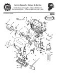
Fig. 2.1 and Fig. 2.2 show the equipment front panel and back panel details.
2.2.
INPUT CLOCK SELECTION
The input reference clock selection can be automatic or manual. On power on or
reset, the NSE comes up in the automatic mode, wherein it selects one of the input
clocks according to a fixed hardwired priority. The order of priority is CLK0, CLK1,
CLK2. If none of clocks are present or available for selection, then the NSE goes
into the free run mode. The operator can override this selection by going to manual
mode and selecting a clock using the keyboard. If the input clock is present, the
LED corresponding to it will glow green. The LED corresponding to the selected
reference blinks once in 2 seconds (1Hz Freq.).
It may be noted that a clock used as Reference to NSE shall always be taken from a
higher level exchange.
6
C-DOT NSE
6
5
BEEPER
ACK
TEST
INSTALLATION AND USER MANUAL
Copy 0 Pwr
LOCK & KEY
FIG. 2.1
FRONT VIEW OF NSE
Copy 1
Copy 0
4
Frc Card
2
Select
Copy 1 Pwr
3
4
3
Copy 1
Frc Clk
1
Mode
MONITORING LED's
Frc Card
COPY 1
FUNCTION KEYS
Frc Clk
Copy 0
LED PANEL
2
Select
COPY Ø
FUNCTION KEYS
1
Mode
TEST KEYS
\DESIGN\NSE-IUM\NSEUMFV
Sys 2
Sys 1
Sys 0
COPY 1
Sys 2
Sys 1
Sys 0
Target Sys Sts
COPY 0
PRODUCT DESCRIPTION
7
8
FUSE 2A
FUSE 2A
RS232 INTERFACE
ON
ON
-48V INPUT
COPY 1
COPY 0
J20
SYNC
c ba
J18
c ba
J3
REF_CLK2
REF_CLK1
J10
J4
J11
J13
J7
8M_1_C0
8M_1_C1
J14
J8
FOR DEBUGGING ONLY
J15
J9
8M_0_C0
8M_0_C1
J16
NSE C1
NIO C1
NIO C0
NSE C0
c
b
a
c
b
a
c
b
a
c
b
a
\DESIGN\NSE-IUM\NSEUMRV
J3, J4, J10 = G.703/10, 2.048 MHz 75 INPUTS
J6 = 2.048 MHz TTL CLOCK OUTPUT
J5, J7, J9, J12, J14, J16 = CLOCK OUTPUTS FOR C-DOT SBM EXCHAMGES
8M_2_C1
J6
J5
J12
2M
c
b
a
c
b
a
c
b
a
c
b
a
8M_2_C0
TEST_CLK
REF_CLK0
123
W1 W2
FIG. 2.2
REAR VIEW OF NSE
J18: CHECK (MONITORING) TRUNKS
J17: POSITION 1,2,3 = REFERENCE TRUNKS
J18: PIN No. 2 & 6 OF BOTTOM MOST
CONNECTOR BLOCK (TWO INPUTS)
J17: PIN No. 2 OF BOTTOM MOST
CONNECTOR BLOCK (ONE INPUT)
W3 W4W5
J17
REF_TRK
c ba
CHECK INPUTS
J19
G.703
c ba
G.703/10 CLOCK OUTPUTS (FOR E-10B AND MAX-L)
SYNC OUTPUT FOR C-DOT SBMs
Chapter 2
C-DOT NSE
INSTALLATION AND USER MANUAL
FIG. 2.3
NSE POWER CABLE CONNECTIONS
L
\DESIGN\NSE-IUM\NSEUMPWR
PRODUCT DESCRIPTION
9
10
5
9
6
25
14
\DESIGN\NSE-IUM\NSEUMRS2
CONNECTOR AT TERMINAL END
13
1
25P DTYPE CONN. FEM.
FIG. 2.4
NSE TERMINAL (RS232) CONNECTOR DETAIL
CONNECTOR AT NSE END
(RS232 INTERFACE)
1
9P DTYPE CONN. FEM.
Chapter 2
C-DOT NSE
PRODUCT DESCRIPTION
2.3.
SYNCHRONISED CLOCK OUTPUTS
The NSE supplies six (6) ITU TG.703/10 (120Ω) output clocks. These can be used for
E-10B exchanges and C-DOT MAX-L exchange. In addition to these, it also gives
six (6) 8MHz (single ended TTL, 75 ohms) clock output along with accompanying
8KHz sync signals (differential TTL) to be used with C-DOT SBM exchanges.
A unique feature of NSE is that in duplex mode of operation, each copy of NSE
supplies half the numbers of output clocks described above and in simplex
operation, the only copy supplies all the output clocks required. This is achieved by
shorting individual card outputs on the motherboard and selecting outputs via
relays. This feature also enables synchronization of exchanges that require
duplicated input clocks as reference clocks.
2.4.
CHECK INPUTS
The NSE can monitor or check clock outputs of the synchronized (target) exchanges
to verify whether they are in synchronisation with the network clock. It can take in
three (3) digital trunks (G.703/6) 120Ω and 3 G703/10, 120Ω clocks supplied from
the target exchanges for monitoring. The digital trunks are connected to the NSE in
non-regenerative mode, i.e., the clock and data information is tapped from the
trunks using high impedance terminations. This results in no disturbance in the
trunks at the destination exchanges where the trunks are terminated with their
characteristic impedance.
2.5.
USER INTERFACE PANEL
NSE has a user-friendly display panel and keyboard arrangement. The display
panel shows the status of various functional blocks of NSE via a set of different
colored LEDs, Alarms are audio-visually indicated, i.e., a beeper accompanies the
LED indications. The keyboard is used for manual operations. Remoting of NSE
alarms is also possible through an opto-coupled interface. A VT-220 emulation is
supported for this purpose. Please refer to Chapter 4 of "C-DOT NSE General
Description" document for more details on the NSE user interface.
2.6.
NSE TERMINAL INTERFACE
Two RS232 Interface are available for each NSE copy as shown in Fig. 2.2. For
debugging purpose a terminal may be connected to NSE as shown in Fig 2.4.
INSTALLATION AND USER MANUAL
11
Chapter 3.
NSE Packaging Details
3.1.
GENERAL
The NSE card cage houses the following four types of cards
a)
NSE Controller and PLL Card (NCP212/H-S01)
b)
NSE Input/Output Card (NIO 499/H-S00)
c)
NSE Display and Keyboard Card (NSD 463/F-O02)
d)
NSE Motherboard Card (NSM 462/F-M02)
NCP and NIO form a single block and can be duplicated to operate NSE in duplex
mode of operation. The NCP and NIO cards sit on the NSM in a card cage with the
following order.
NCP copy 0 ------------
slot 1 (top)
NIO copy 0 ------------>
slot 2
NIO copy 1 ------------>
slot 3
NCP copy 1 ------------>
slot 4 (bottom)
The NSD card is mounted on the front panel of the NSE and is connected to
both copies of NCP through 40 pin FRC connector cables.
3.2.
FIRMWARE DETAILS
S.No.
12
Device
Card
Position
Checksum
1.
EPROM 27C010
NCP
U17
AB23
2.
EPROM 27C010
NCP
U19
2B52
3.
EPLD 7128E
NCP
U56
1B7916
4.
EPLD 7128E
NIO
U22
1A6DC5
5.
EPLD 7128E
NIO
U12
1660D9
6.
EPLD 7128E
NIO
U13
1660D9
C-DOT NSE
NSE PACKAGING DETAILS
S.No.
3.3.
Device
Card
Position
Checksum
7.
PAL 22VI0
NIO
U19
3F84
8.
PAL 22VIO
NIO
U21
53AA
9.
Serial PROM
NIO
U24
F6116
JUMPER DETAILS FOR NCP CARD
Jumper
Status
Function
W1
Short
Usage of write operation to FLASH PROM possible
(U17)
W2
Short
Usage of write operation to FLASH PROM possible
(U19)
W3
Short
Connects AGND to Gnd
W4 (1-2)
Short
Connects CLK~as strobe to DS1232 (to be done when
emulator is used instead of IMP)
W4 (2-3)
Short
Connect AS~ as strobe to DS1232
W5 (1-2)
Short
For Level 2 operation*
W5 (2-3)
Short
For Level 4 operation*
W6
Open
To use direct clock as Reference 0 to PLL
W6
Short
To use digital trunk as Reference 0 to PLL
W7
Open
To use direct clock as Reference 1 to PLL
W7
Short
To use digital clock as Reference 1 to PLL
W8
Open
To use direct clock as Reference 2 to PLL
W8
Short
To use digital trunk as Reference 2 to PLL
W9 (1-2)
Short
Connect Ext Osc Clock (8600) to PLL
W10
Short
For Level 2 operation*
W10
Open
For Level 4 operation*
W11
Open
For Level 2 operation*
W11
Short
For Level 4 operation*
W12 (1-2) Short
To disable spare 2 MHz TTL O/P at connector
W12 (2-3) Short
To enable spare 2 MHz TTL O/P at connector
INSTALLATION AND USER MANUAL
13
Chapter 3.
Jumper
Status
Function
W13 (1-2) Short
To get 2 MHz Clock O/P at connector J6
W13 (2-3) Short
To get 16 MHz Clock O/P at connector J6
W14
Short
If PSI is mounted
W14
Open
If PS2 is mounted
W15
Short
If PS2 is mounted
W15
Open
If PS1 is mounted
Note: Position of jumper W5, W10 and W11 decide the level 2 or level 4 operation of NSE.
* Other jumper settings may be left as per factory default settings as shown.
3.4.
JUMPER DETAILS FOR NIO CARD
Jumper
W1
W2
W3
Status
Function
Short
To connect Ref-Trk1 (G.703/6) to phase
detector
Open
To connect reference clk 1 to phase detector
Short
To connect Ref-Trk0 (G.703/6) to phase
detector
Open
To connect reference clk 0 to phase detector
Short
To connect Ref-Trk2 (G.703/6) to Phase
Detector
Open
To connect reference clk 2 to phase detector
Note : Position of jumpers W6, W7, W8 on NCP card and W2, W1 and W3 on NIO
card decide whether a reference trunk is selected or reference clock is selected by
NSE.
14
C-DOT NSE
Chapter 4.
NSE Integration with Exchange
4.1.
INTRODUCTION
NSE can be integrated with E-10B exchanges, C-DOT SBMs and MAX-L exchanges.
The connectivity details and procedure of integration is described for each exchange
separately in the following sections.
4.2.
4.2.1.
NSE INTEGRATION WITH E-10B EXCHANGES
General
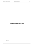
NSE can supply clock to three E-10B exchange simultaneously at the same
location. The connectivity detail is shown in Fig. 4.1.
All E-10B exchanges
recommendation.
4.2.2.
accept
clock
input
as
specified
by
G.703
Procedure to Integrate NSE with E-10B
a)
Make connections as shown in Fig. 4.1(a), 4.1(b), 4.2(d), 4.2(e), 4.2(f)
and Fig. 2.3.
b)
Power on NSE in level 2 mode and wait for 2 hrs. ‘O/P’ LED, ‘AUTO’
LED and ‘FREE RUN’ LED on NSE display panel shall glow green.
This indicates that NSE is ready for use.
c)
Connect PCMs (Maximum 3) coming from a TAX at higher level to
NSE at Ref-Trk connector [J17]. Let NSE select a PCM as reference
and synchronise to it. The maximum synchronisation time can be
around 10-12 hrs. NSE in ‘SYNCH’ mode shall be indicated by the
‘LOCK’ LED glowing on the display board.
d)
Physically connect NSE 2.048 MHz, G.703 output from connector J19
to the top runway tag block at the back of the BT bay of E-10B
exchange.
e)
Jack in the CIT1 card in the E10B exchange.
INSTALLATION AND USER MANUAL
15
Chapter 4.
INPUT PCMs
FROM HIGHER LEVEL1 TAX
Rx
1
Rx
2
1
Rx
Rx
3
2
Rx
3
Rx
TO URM
REF_TRK CONNECTOR
J17
C-DOT
NSE
CHECK INPUT
CONNECTOR
G.703 OUTPUT CLK
CONNECTOR
J18
J19
CHECK INPUT
TO NSE
INPUT TIMING IN BT
FEEDBACK
TIMING
TO NSE
BT BAY
B
R
B
(RUNWAY TAG BLOCK)
R
+ -
+ -
L2
L1
E-10B
EXCHANGE
URM
ISYM CARD
SLIP COUNTER
FIG. 4.1a
NSE CONNECTIVITY WITH E-10B EXCHANGE
\DESIGN\NSE-IUM\NSEUMCE
16
C-DOT NSE
INSTALLATION AND USER MANUAL
6
7
5
4
3
1
2
a
6
7
5
4
3
1
2
a
ACB-NSEXMNCX-00
120 Ω TWISTED PAIR CABLE
-
TAG BLOCK ON
TOP OF BT BAY
SLOT 49
+
L2
-
+
L1
6
7
8
9
1
2
3
4
5
CIT1 CARD
IN BT BAY
\DESIGN\NSE-IUM\NSEUMCDE
FIG. 4.1b
CONNECTION DETAILS FOR E10B EXCHANGE INTERFACE
NSE J18
TAB 1/2/3
(MONITORING CLOCK CONNECTOR)
c
ACB-NSEX-2MCX-000
120 Ω TWISTED PAIR CABLE
EXISTING CABLE BETWEEN
CIT1 CONNECTOR &
BT BAY TOP TAG BLOCK
120 Ω TWISTED FOUR PAIR SHIELDED CABLE LENGTH IS TO BE KEPT TO THE MINIMUM POSSIBLE LENGTH (10-15) AS PER
SITE REQUIREMENT (ALSO TO THE BT RACK)
NSE J19
TAB 1/2/3
(REF.-TRK CONNECTOR)
c
NOTE :-
NSE INTEGRATION WITH EXCHANGE
17
Chapter 4.
f)
Change the switch on BT bay from INDEPENDENT mode to SYNC
mode. Also reset the button on BT. All the existing non-urgent alarms
should disappear on the HASU card of E-10B exchange.
g)
To verify that NSE output is supplying clock to the E-10B, connect the
Monitoring input (check input) of NSE on connector J18 to the point
shown on the BT bay as shown in the Figure 4.1a. The SYS0 LED on
NSE display panel shall light up.
h)
Slip at E-10B can be monitored by connecting the slip counter at BT
bay at the point shown in the figure.
i)
The slip values on counter shall be noted on daily basis at a particular
time one day before and after synchronisation.
Note :
a)
If 'MSEXT' alarm on BT (CIT-1) is red then give a reset to 'HASU' card
and press 'RZLP' switch on 'HASU'.
The 'MSEXT' alarm shall be off to show proper operation.
4.2.3.
b)
The NSE 2MHz G.703 output cable length shall be not more than
15 meters.
c)
No oscillator drift messages should apear
Preventive Maintenance at E-10B
E-10B’s local clock (given by HOSA cards) may drift with passage of time
(oscillator stability 10-6). Therefore, before synchronisation, the HOSA card
voltages should be checked on Vas points of all three HOSA cards. The
voltage indicated shall be in between 1.45V to 1.55 V D.C.
If voltages are found to be out of the above mentioned range, these should be
adjusted with the help of a potentiometer mounted on the cards.
Note: Tolerance values may vary from card to card. So if FNU alarm on
HASU is present after connecting to NSE (ie after switch over from
independent to synchronize mode, HASU card can be tuned to match and
RZLP pressed to remove the alarm. Tuning to be done to the effect that no
alarm is present both in independent & synchronize mode.
4.3.
4.3.1.
NSE INTEGRATION WITH C-DOT SBMs
General
C-DOT SBM accept a timing input of 8,192 MHz. NSE4 supplies three
duplicated 8.192 MHz TTL clock output along with 8 KHz SYNC signal.
18
C-DOT NSE
NSE INTEGRATION WITH EXCHANGE
Thus a single NSE can synchronise three co-located C-DOT SBMs
simultaneously.
4.3.2.
Procedure to Integrate C-DOT SBMs with NSE
a)
Set NSE as given in section 3.2, 3.3 & 3.4 in level 4 mode.
b)
Power on NSE. NSE shall be ready when AUTO, OUTPUT and FREE
RUN LED on NSE display panel get switched on.
c)
Make connections as shown in Fig. 4.2(a), 4.2(b), 4.2(c), 4.2(d), 4.2(e),
4.2(f), and 2.3.
d)
At CRP terminal of exchange, give command MOD-CLKSRC-EQPAG
to equip NSE in the system. Response on the terminal shall indicate
equipage of NSE. Also an URGENT alarm shall be raised on OOD
terminal and on ADP.
e)
Give SEL-CLK-SRC command to select NSE-0 (NSE clock available to
TSC-0 of SBM) or NSE-1 (NSE clock available to TSC-1 of SBM).
Response shall indicate the selection of NSE-0 or NSE-1 clock. Also the
‘URGENT’ alarm shall change to ‘NORMAL’ on OOD and ADP.
f)
Give DISPL-CRNT-CLK-SRC command to ensure that NSE-0/NSE-1 is
the selected clock in the system.
g)
Repeat (f) of 4.3.3.
Note :
Care must be taken that if NSE is to supply output to SBM local exchange, it
shall be set in level 4 mode before power on and if NSE is to supply output to a
SBM TAX then it shall be set in level 2 mode before power on. The Mode
settings are explained in section 3.3.
4.3.3.
Procedure for Integration of NSE with C-DOT Exchanges (MAX-L)
a)
Make connections as shown in Fig. 4.3(a), 4.3(b), 4.2(d), 4.2(e), 4.2(f),
and Fig. 2.3 for MAX-L exchange.
b)
At NSE check up the jumper settings at both NIO and NCP cards as
described in Chapter 3. Also set NSE in level 2 mode.
c)
Power on NSE and wait for 2 hours for warm-up. After 2 hours AUTO,
ACTIVE and FREERUN LED shall light up. Connect three reference
trunks to NSE at J17 Tab 1/2/3,as shown in Fig. 4.2 (d).
CLK0 and LOCK LED starts blinking indicating that NSE has started
locking to CLK0. After 10-12 hours LOCK LED shall become steady
INSTALLATION AND USER MANUAL
19
Chapter 4.
and indicates that NSE is completely locked to the input reference i.e.
CLK0.
d)
At MAX-L exchange end, the clock cards i.e. SCK-02 cards in both
copies need to be replaced with SCK-04 cards for NSE integration.
Hence force out standby SCK-02 card and replace it with SCK-04 card.
Force in this SCK copy. Now force out the other SCK-02 card and
replace it with SCK-04 card. Force in service this SCK copy also.
e)
At CRP terminal give the following commands:
f)
1.
MOD-CLKSRC-EQPAG to equip NSE clock. The response on
CRP terminal shall indicate equipage of NSE clock. Also an
urgent alarm on OOD and ADP shall be raised indicating the
equipage of NSE clock.
2.
SEL-CLK-SRC to select NSE-0 (NSE clock connected to SCK-0
copy) or NSE-1 (NSE clock connected to SCK-1 copy). Urgent
alarm from OOD & ADP shall be removed.
3.
DISPL-CRNT-CLK-SRC command to display which clock is
selected by the exchange i.e. NSE-0, NSE-1, CLK-0 (SCK-0) or
CLK-1 (SCK-1).
Connect a cable at DTS monitor port (corresponding to the selected
reference at NSE) and the IOP to get slip dumps using PORTMON and
SLIP utility as explained in Chapter 7.
Note :
20
a)
Care must be taken that NSE 2 MHz output cable length shall
not be more than 10-15 meters.
b)
SCK-04 card shall be used only when NSE output is connected to
it.
C-DOT NSE
NSE INTEGRATION WITH EXCHANGE
C-DOT SBM
8KHz SYNC
(TAB POSITION
FOR
REFERENCE CLKØ)
PCMs FROM *
HIGHER LEVEL
EXCHANGE
{
PCM1
PCM2
PCM3
1
2
3
13A
TSS-0
12B
TSC-0
CONNECTOR
(REF_TRK)
8.192MHz
CLOCK CABLE
J5
J17
C-DOT
NSE
CONNECTOR
(SYNC OUT)
CLOCK CABLE
J20
J12
15B
8.192MHz
14A
TSC-1
TSS-1
8KHz SYNC CABLE
LEGEND
TSS = TIME SWITCH CARD
TSC = TIME SWITCH CONTROLLER CARD
* = REFER FIG. 4.2d AND 4.2e
FIG. 4.2a
NSE CONNECTIVITY WITH C-DOT SBM
\DESIGN\NSE-IUM\NSEUMCS
INSTALLATION AND USER MANUAL
21
Chapter 4.
TSS-0
c
NSE END
SYNC
c
a
(ACB-NSEXSYNX-000)
1
TSS-1
a
c
a
1
1
2
2
3
3
4
4
5
5
6
6
7
7
2
13A POSITION2
14A POSITION2
TSS-0
TSS-1
3
4
5
6
7
a
c
J20
(TAB 1/2/3)
c
a
1
1
2
2
3
3
4
4
5
5
6
6
7
7
13A POSITION3
14A POSITION3
FIG. 4.2b
CONNECTION DETAILS FOR C-DOT SBM EXCHANGE INTERFACE
(SYNC CABLE)
\DESIGN\NSE-IUM\NSEUMDS1
22
C-DOT NSE
NSE INTEGRATION WITH EXCHANGE
TSC-0
c
a
1
2
3
SPINNER
CONNECTOR
4
(ACB-NSEX8MCX-000)
GND
CLK
5
J5
8.192MHz
6
7
NSE END
8.142MHz
12B, POSITION 1
TSC-1
c
a
1
2
3
SPINNER
CONNECTOR
4
(ACB-NSEX8MCX-000)
GND
CLK
5
J12
8.192MHz
6
7
NSE END
8.142MHz
15B, POSITION 1
FIG. 4.2c
CONNECTION DETAILS FOR C-DOT SBM EXCHANGE INTERFACE
(CLOCK CABLE)
\DESIGN\NSE-IUM\NSEUMDS
INSTALLATION AND USER MANUAL
23
Chapter 4.
'')
6:,7&+ 5220
7[ )520 /2&$/
7[
6:,7&+ 5220
7[
&'27
5()
'7. 5[ 72 /2&$/
)520
6:,7&+ 5220
7$;
'78 ,1
25
5[
5[
7$* %/2&. $
7$* %/2&. %
7(50,1$7,1*
7(50,1$7,1*
0E ',*,7$/
0E ',*,7$/
7581.6 )520
7581.6 )520
7$;
6:,7&+ 5220
850 ,1
(%
(;,67,1*
-803(56
Figure: 4.2d
EXISTING ARRANGEMENT IN DDF BEFORE INSTALLATION OF NSE
Notes: (Refer fig 4.2d and 4.2e)
a)
Initially the Tx-Rx exist at DDF as shown in fig 4.2d
b)
Rx pair to be isolated and connected to separate tab blocks, i.e. routed in serial
mode via NSE as shown in fig 4.2e.
c)
Rx pair from distant exchange terminates at NSE on la-lc pair of J 17 tab 1 via
DDF and another pair from 5a-5c of J17 tab 1 at NSE (i.e. same 7/2 connector)
goes back to DDF and is routed to the exchange via separate termination.
d)
3 nos. of 2 Mb digital trunks from trunk group connected to tax may be chosen
as reference digital trunks.
Contd…on page 25
24
C-DOT NSE
NSE INTEGRATION WITH EXCHANGE
'')
6:,7&+ 5220
7[ )520 /2&$/
7[
6:,7&+ 5220
7[
'78 ,1
5()
'7. 6:,7&+ 5220
)520
7$;
&'27
5[ 72 /2&$/
25
5[
850 ,1
5[
(%
7$* %/2&. $
7$* %/2&. %
7(50,1$7,1*
7(50,1$7,1*
0E ',*,7$/
0E ',*,7$/
7581.6 )520
7581.6 )520
7$;
6:,7&+ 5220
(;,67,1*
1(: -803(56
-803(56
1(: -803(56
1(: 3$,5
7$* %/2&.
1&
1&
%/
:+
*1
:+
25
:+
%1
:+
D
F
D
F
D
F
D
F
5()(5(1&( ',*,7$/ 7581. &$%/(
$66(0%/(' 3$57 1R $&%16(;'75;
0$; &$%/( /(1*7+ 0WV
&211(&725 ,1
16( - 7$%
Figure 4.2e
CHANGES TO BE DONE IN DDF FOR ROUTING REFERENCE DIGITAL TRUNK CABLE TO NSE
Continued
from page 24
a)
NOTE :(Refer figures 4.2d , 4.2e)
e)
Reference digital trunks may be terminated on NSE as follows
Ref. DTK1 : NSE J17 tab 1, Ref. DTK2 : NSE J17 tab 3 , Ref. DTK3 : NSE
J17 tab 3
f)
For terminating reference digital trunks do the following
•
Remove existing jumpers from Rx to Rx for ref. digital trunks between tag
blocks A & B
•
Terminate Rx pairs of ref.digital trunk 1 from tab blocks on 7x2 connector
for NSE J17 tab1 as shown in fig.4.2e
•
Similarly, terminate Rx pairs of ref.digital trunks 2 & 3 on two different 7x2
connectors for tab 2 & tab 3 of NSE connector J17.
•
Keep 7 x 2 connectors always plugged in NSE J17 connector to avoid break
in Rx pairs of digital trunks going to switch room.
INSTALLATION AND USER MANUAL
25
Chapter 4.
&211(&7,9,7<',$*5$0
16( (1'
F
[
[
[
[
[
[
[
D
7[ 3$,5 2) 7581. )520 7$; (;&+$1*(
6285&,1* 1: &/2&.
72 '')
5[ 3$,5 2) 7581. 72 /2&$/ (;&+$1*(
NOTE: 1) LENGTH OF THE CABLES DEPENDS ON SITE. (NOT MORE THAN 20 MTRS)
Figure 4.2f
DIGITAL TRUNK CABLE EXTERNAL
26
C-DOT NSE
NSE INTEGRATION WITH EXCHANGE
1
LEVEL 2 PCMs
FROM DDF
OR
FROM DTS
2
3
REF_TRK CONNECTOR
J17
C-DOT
NSE
7/2 CONNECTOR
J19
G.703 CLK OUTPUT
INPUT TIMIMG IN MAX-L
SCK-0
7/2 CONNECTOR
SCK-1
7/2 CONNECTOR
11A
16A
C-DOT MAX-L
DTS
IOP
(SLIP DUMPS)
FIG. 4.3a
NSE CONNECTIVITY WITH MAX-L EXCHANGE
\DESIGN\NSE-IUM\NSEUMCNW
INSTALLATION AND USER MANUAL
27
Chapter 4.
MAX-L END
DESTINATION SCU FRAME
COPY Ø 11A POSITION1 (TAB1)
c
a
1
2
3
4
NSC END
SOURCE
c
5
6
a
7
1
2
3
4
5
6
c
7
a
1
2
J19
(TAB 1,2,3)
(ACB-NSEX2MCX-000)
3
4
5
6
7
COPY1
16A POSITION1 (TAB1)
SCU FRAME
FIG. 4.3b
NSE CONNECTIVITY WITH C-DOT MAX-L EXCHANGE
NOTE:IF THE CABLE HAS A CONNECTOR WITH ONLY ONE PAIR FOR CONNECTING TO COPY Ø OF MAX-L (POSITION 11A),
CONNECTION SHOWN IN DIAGRAM MAY BE MADE FOR COPY1 ALSO (POSITION 16A) AT SITE.
\DESIGN\NSE-IUM\NSEUMDM
28
C-DOT NSE
Chapter 5.
Slip Monitoring
5.1.
5.1.1.
SLIP MONITORING IN C-DOT DSS
Introduction
Slip monitoring is done in C-DOT DSS at the DTS (Digital Trunk
Synchronisation) card and slips are dumped and analysed at the IOP using
two slip monitoring utilities namely "PORTMON" and "SLIP".
PORTMON is an inherent part of UNIX Release 9.0 and in onward releases
and the other utility named SLIP is a post-processing utility and is available
in UNIX releases 11.2 and higher.
5.1.2.
Prerequisite
Check for the following :
5.1.3.
1.
DTS card shall be jacked in.
2.
A RS232 cable between the selected DTS and IOP. (Please refer to
Figures 5a & 5b for connection details when IOP ML / IOPXL is used
and figures 5c and 5d for connections when IOPVH is used).
Procedure
(A)
PORTMON Utility
1.
At IOP prompt make a command file "/tmp/cmd and write the
following commands in this file.
i)
Contrl-C (in first line)
ii)
C (in second file)
Press <enter> and <save> the file
2.
Again, at IOP prompt, give Iop5C> echo "N\c">>/cmd and press enter
INSTALLATION AND USER MANUAL
29
Chapter 4.
3.
Connect the cable between the DTS card (Monitor port) to any of
the icc port at the IOP (i.e. icc5)
Care must be taken that the action field entry of the selected icc
port in /etc/inittab file should be marked "OFF".
4.
Invoke PORTMON Utility by giving the following command at
IOP prompt
IOP5C> Portmon –c
System shall ask for the port number thus enter 5
System asks for the input file name thus give the full path
/tmp/cmd
System asks for file name where slip values are desired to be
dumped give
/tmp/slip.log
Now System asks for the baud rate enter 4800
System asks again for Port No. enter – 1
The utility shall start dumping slip values in slip.log file
Each line starting from N represent a frame slip hence we can
calculate from these values, the number of frame slips occurred
every 10 minutes as the time stamp is printed every 10 minutes.
(B)
SLIP Utility
This utility will convert the Slip values in hex stored via PORTMON
utility to a more user friendly format in decimal.
It may be noted that this utility is an inherent part of UNIX releases
after 11.2 and higher.
At IOP prompt, please give one of the following options:
(i)
Slip –c –m X <slip.log
(ii)
Slip –c –h Y <slip.log
Where 'X' is the time interval in minutes for which slips are to be
calculated by the utility (The value of X shall be either 10 or a multiple
of 10)
Where 'Y' is time interval in hours for which slip has to be calculated.
Where 'slip.log' is the file available after running PORTMON Utility.
30
C-DOT NSE
SLIP MONITORING
Note :
Tec specifications
a)
The output clocks should have a minimum stability of 2x10E-10
per day.
b)
The NSE should be able to give audible alarm for various critical
and non critical faults.
c)
NSE should have fitter absorbtion characteristics and fitter
transfer characteristics as specified in ITU g.823 standards.
INSTALLATION AND USER MANUAL
31
Chapter 4.
CONNECTOR B
TAB 2 (FOR DTSØ)
TAB 3 (FOR DTS2)
1
2
3
c
a
4
1
2
5
3
6
7
4
5
MODEM CABLE
8
6
9
7
10
11
7/2 CONNECTOR
12
AT DTU END (MONITOR PORT)
13
14
15
16
17
18
19
20
FIG. 5a
21
22
CONNECTION DETAILS OF SLIP MONITORING CABLE
FOR DTSØ & DTS2
23
24
25
D-25 FEMALE CONNECTOR
AT IOP ML END
CONNECTOR B
TAB 2 (FOR DTS1)
TAB 3 (FOR DTS3)
1
2
3
c
a
4
1
2
5
3
6
7
4
5
MODEM CABLE
8
6
9
7
10
11
7/2 CONNECTOR
12
AT DTU END (MONITOR PORT)
13
14
15
16
17
18
19
20
21
22
23
FIG. 5b
24
25
D-25 FEMALE CONNECTOR
CONNECTION DETAILS OF SLIP MONITORING CABLE
AT IOP END
FOR DTS1 & DTS3
\DESIGN\NSE-IUM\NSEUMMC1
32
C-DOT NSE
SLIP MONITORING
CONNECTOR B
TAB 2 (FOR DTSØ)
1
TAB 3 (FOR DTS2)
c
a
1
2
2
3
3
CONNECTOR AT
IOP-VH END
4
4
2
5
5
3
6
6
4
7
7
5
8
8
1
6
9
9
2
7
10
10
3
11
11
4
12
12
5
13
13
6
14
14
7
15
15
8
16
16
9
17
17
18
18
19
19
20
20
21
21
22
22
23
23
1
7/2 CONNECTOR
AT DTU END (MONITOR PORT)
FIG. 5c
CONNECTION DETAILS OF
SLIP MONITORING CABLE
FOR DTSØ & DTS2
24
24
25
25
D-25 FEMALE CONNECTOR
25 PIN MALE
TO 9 PIN FEMALE
CONVERTER
CONNECTOR B
TAB 2 (FOR DTS1)
TAB 3 (FOR DTS3)
c
a
1
1
2
2
3
3
4
4
2
5
5
3
6
6
4
7
7
5
8
8
1
6
9
9
2
7
10
10
3
11
11
4
12
12
5
13
13
6
14
14
7
15
15
8
16
16
9
17
17
18
18
1
7/2 CONNECTOR
AT DTU END (MONITOR PORT)
FIG. 5d
CONNECTION DETAILS OF
SLIP MONITORING CABLE
FOR DTS1 & DTS3
19
19
20
20
21
21
22
22
23
23
24
24
25
25
D-25 FEMALE CONNECTOR
25 PIN MALE
TO 9 PIN FEMALE
CONVERTER
\DESIGN\NSE-IUM\NSEUMMC1a
INSTALLATION AND USER MANUAL
33
Chapter 6.
Debugging Aids for NSE
•
The following table describes the various faults that might develop in NSE cards
and also the proposed solution for each case.
No.
Symptom
1
RESET LED (ON
NCP) glowing Red
continuously
Possible Reasons
(i) EPROMs not mounted
properly
(ii) Pins of EPROMs bent or
broken
(iii) Processor not mounted
properly
Action
(i) Mount the PROMs
as per release
information
(ii) Check the output
voltage at point on
NCP card (VCC
print).
(iv) PSU on NCP failed
(v) Processor in Halt state
due to address error/bus
error caused due to
short/open in address/data
bus
2
RESET LED glows (i) PSU of NCP card failed
red intermittently
(ii) No watchdog signal to
DS12320
(i) Noise spikes can
be seen in +5V VCC
on CRO
(ii) Check all jumper
settings on NCP card
3
CARD FAIL LED
glows
(i) NIO card not jacked in
properly
(ii) PSU on NIO card facility
(iii) Jumper setting on NIO
not proper
(i) Check power LED
(DS1) on front panel
of NCP
(ii) Check jumper
settings on NIO card
(iv) EPLDs and FPGA in NIO
not mounted properly
34
C-DOT NSE
DEBUGGING AIDS FOR NSE
No.
4
5
Symptom
OUTPUT LED
fails to glow
DIAGNOSTICS on
cards fail on
POWER ON
Possible Reasons
Action
(i) Output drivers of 8MHz
and 8 KHz sync on NCP card
or 2MHz output on NIO card
may have gone faulty
(i) Change NCP card
if 8 MHz or 8KHz
sync signal is found
to be missing.
(ii) EPLD on NCP faulty
(ii) Change NIO card
if 2 MHz signal is
missing.
(i) PSU onboard NCP may be
faulty
(i) Check for +5V on
VCC point. If no
voltage, change NCP
card.
(ii) Power I/P connections to
NSE(-48V) faulty or reversed
(ii) -48V connection
shall be as per
installation manual
6
7
FAN FAIL LED
glows red
Both cards copies
come up as active
(i) Fan may be faulty
(ii) Fan fail circuit in NCP
faulty
(i) Mate to mate
communication failed due to
faulty RS232 drivers in NCP
(i) Replace fan if
faulty
(ii) Replace NCP card
if fan is running
(i) Replace NCP card
(ii) Reset signal drivers to
each card is faulty
8
NSE fails to lock
with any of
reference
INSTALLATION AND USER MANUAL
(i) Jumper settings not
proper in NCP
(i) Check all jumper
settings on NIO and
NCP card.
35
System
Practices
COMMENTS
The following comments pertain to:
Document Name
CSP Section
-
Issue/Draft
,
No.
-
(Month)
(Year)
COMMENTS :
(Use a separate sheet if required)
Please mail your comments to:
Centre for Development of Telematics
Attn:
Mr. Y.K. Pandey
Director, Systems
39, Main Pusa Road
New Delhi 110 005
Tel.: +91-11-5740374
Fax: +91-11-5756378
Your Reference:
Name
:
Designation :
Company
:
Address
:
Tel. :
Fax :