1
Hardware Setup
7.1 Hardware set-up and jumpers configuration
Building the system using the modules of the Tower System is not difficult. The peripheral modules and the MCU module
are plugged into the elevator connectors, while the white stripe on the side of the module boards determines the orientation to
the Functional elevator (the elevator with the mini USB connector, power supplies and the switch).
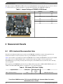
It is necessary to configure jumpers on both the TWR-KV10Z32 module and the TWR-MC-LV3PH module. The jumper
settings for TWR-KV10Z32 board are listed and highlighted in the following table.
Table 4. Jumper Settings of TWR-KV10Z32 Board
Jumper #
Setting
Jumper #
Setting
J1
2-3
J14
open
J2
1-2
J18
2-3
J3
2-3
J19
2-3
J4
1-2
J20
2-3
J5
1-2
J21
3-4
J7
1-2
J22
3-4
J8
2-3
J25
open
J9
1-2
J26
1-2
J10
2-3
J27
1-2
J11
open
J28
1-2
J12
open
J29
1-2
J13
open
Three-Phase PMSM Sensorless FOC Using the MKV10Z32 with Automated Motor Parameters
Identification, Rev. 0, 12/2014
Freescale Semiconductor, Inc.
17