1
Section 2
DPE+ Installation
This section provides step-by-step instructions for replacing a DPE in a Scanner 1140 or
Scanner 1131 with a DPE+ transducer.
The upgrade may require the following additional tasks:
• If used in a Class I, Div. 1 intrinsically safe installation, the installation of a barrier
adapter
• Upgrade of the PIC micro-controller (Scanner 1131 only)
New Scanner firmware is also required to support communications with the DPE+
transducer. See Sections 3 and 4 for instructions on flashing new firmware to the Scanner.
Replacing the DPE+ Transducer
Explosion Hazard. Do not disconnect equipment unless power has been
switched off or the area is known to be non-hazardous.
WARNING
Static electricity can damage the DPE+ transducer. Use proper anti-static
techniques to establish an earth ground (such as wearing anti-static wrist
strap or touching metal) prior to removing the DPE+ from the anti-static bag.
CAUTION
1.
2.
3.
4.
5.
6.
Power down the Scanner.
Remove the tubing or manifold from the DPE.
Attach a static ground strap to your wrist and a Scanner ground.
Remove the ground screw from the DPE nut inside the enclosure.
Loosen the DPE nut on the outside of the enclosure.
Remove the DPE nut inside the enclosure using a 1 11/16-in. or adjustable wrench. It may
be necessary to place a wrench on the DPE neck or body for leverage.
7. Unplug the DPE cable from the Scanner board.
8. Remove the DPE from the enclosure.
9. Examine the gaskets and replace as necessary to maintain a weatherproof enclosure. Two
gaskets are supplied with each DPE+.
Gasket Options
For metal enclosures, the gasket is installed between the DPE+ and the enclosure.
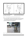
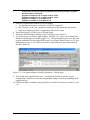
For fiber-reinforced plastic (FRP) enclosures, see options shown in Figure 2.1, page 8.
January 2009
Page 7
Section 2