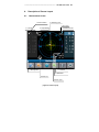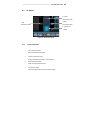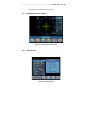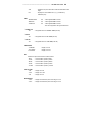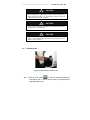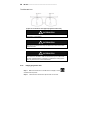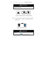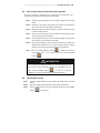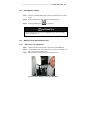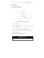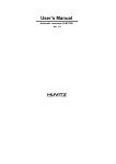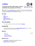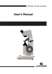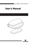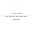
1
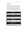
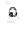
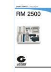
------------------------------------------------------------------------- LM-7800 User Guide 1 IMPORTANT NOTICE This product may malfunction due to electromagnetic waves caused by portable personal telephones, transceivers, radio-controlled toys, etc. Be sure to avoid having objects such as, which affect this product, brought near the product. The information in this publication has been carefully checked and is believed to be entirely accurate at the time of publication. LUXVISION assumes no responsibility, however, for possible errors or omissions, or for any consequences resulting from the use of the information contained herein. LUXVISION reserves the right to make changes in its products or product specifications at any time and without prior notice, and is not required to update this documentation to reflect such changes. LUXVISION 9990 NW 14 Street Doral, FL 33172 All rights are reserved. Under copyright laws, this manual may not be copied, in whole or in part, without the prior written consent of LUXVISION. 2 LM-7800 -------------------------------------------------------------------------- CONTENTS 1. INTRODUCTION ...................................................................................................... 4 1.1. OUTLINE OF THE INSTRUMENT ................................................................................. 4 1.2. CLASSIFICATION...................................................................................................... 4 2. SAFETY INFORMATION ......................................................................................... 5 2.1. INTRODUCTION ....................................................................................................... 5 2.2. SAFETY SYMBOLS ................................................................................................... 6 2.3. ENVIRONMENT FACTORS ......................................................................................... 7 2.4. SAFETY PRECAUTIONS ............................................................................................ 9 3. FEATURES ............................................................................................................ 11 4. NOTES FOR USING THE INSTRUMENT ............................................................. 12 5. CONFIGURATIONS ............................................................................................... 13 5.1. MAIN UNIT ............................................................................................................ 13 5.2. ACCESSORIES....................................................................................................... 15 6. SETTINGS AND PREPARATION FOR OPERATING ........................................... 16 6.1. RECEIVING INSPECTION ......................................................................................... 16 6.2. TEST AT START-UP................................................................................................ 16 6.3. DISPLAY PROTECTION FUNCTION ........................................................................... 17 7. BUTTONS FOR OPERATIONS ............................................................................. 18 7.1. SWITCHING SCREEN ACCORDING TO THE BUTTON SELECTION ............................... 18 7.2. USAGE OF BUTTONS .............................................................................................. 19 8. DESCRIPTION OF SCREEN LAYOUT ................................................................. 21 8.1. MEASUREMENT SCREEN ....................................................................................... 21 8.2. ABOUT THE PROGRESSIVE DISPLAY ........................................................................ 24 ------------------------------------------------------------------------- LM-7800 User Guide 3 8.3. UV SCREEN .......................................................................................................... 25 8.4. CONTACT LENS DISPLAY (SOFT, HARD).................................................................. 26 8.5. D-SUNGLASSES LENS DISPLAY .............................................................................. 27 8.6. SETUP SCREEN ..................................................................................................... 27 8.7. PRINTOUT FORMAT ................................................................................................ 32 9. MEASUREMENTS .................................................................................................. 33 9.1. NORMAL LENSES ................................................................................................... 33 9.2. FRAMED LENSES.................................................................................................... 35 9.3. PROGRESSIVE MULTI-FOCAL LENSES ..................................................................... 37 9.4. GENERAL MULTI-FOCAL LENSES .......................................................................... 444 9.5. SOFT CONTACT LENSES (CONTACT LENS ZIG IS OPTIONAL) ...................................... 45 9.6. HARD CONTACT LENSES ........................................................................................ 45 9.7. TRANSMISSION RATIO OF UV LIGHT ....................................................................... 46 9.8. D-SUNGLASSES LENSES ........................................................................................ 47 9.9. MARKING FOCUS AND CYLINDRICAL AXIS ............................................................... 47 9.10. 10. PRISM ............................................................................................................... 48 MAINTENANCE .................................................................................................... 499 10.1. REPLACING PRINTING PAPER ........................................................................... 499 10.2. REPLACING FUSE ............................................................................................... 50 10.3. STORAGE .......................................................................................................... 51 10.4. DISPOSAL .......................................................................................................... 52 11. TROUBLESHOOTING .......................................................................................... 533 11.1. VARIOUS MESSAGES ........................................................................................ 533 11.2. HOW TO CLEAN PIN HOLE.................................................................................... 53 12. SPECIFICATIONS .................................................................................................. 54 13. SERVICE INFORMATION ...................................................................................... 55 4 LM-7800 -------------------------------------------------------------------------- 1. Introduction 1.1. Outline of the instrument The Automatic Lens meter LM-7800 is the equipment for measuring the refractive power of lenses and gives the spherical, cylindrical and axis of the lenses. The Automatic Lens meter LM-7800 also contains the PD(=pupil distance) measurement and the UV Protection Ratio Test. The automatic lens meter LM-7800 can measure both the uncut singular lenses and the framed glasses. Recently the Bi-Focal lenses or Progressive lenses for the elderly can be check with this equipment. And also this instrument can measure soft contact lenses easily and accurately using the specialized mechanical jig and the detailed display. 1.2. Classification Protection against electric shock: Class I(earthed) Installation Category: II Pollution Degree: 2 ------------------------------------------------------------------------- 2. LM-7800 User Guide 5 Safety Information 2.1. Introduction Safety is everyone’s responsibility. The safe use of this equipment is largely dependent upon the installer, user, operator, and maintainer. It is imperative that personnel study and become familiar with this entire manual before attempting to install, use, clean, service or adjust this equipment and any associated accessories. It is paramount that the instructions contained in this manual are fully understood and followed to enhance safety to the patient and the user/operator. It is for this reason that the following safety notices have been placed appropriately within the text of this manual to highlight safety related information or information requiring special emphasis. All users, operators, and maintainers must be familiar with and pay particular attention to all Warnings and Cautions incorporated herein. ! WARNING “Warning” indicates the presence of a hazard that could result in severe personal injury, death or substantial property damage if ignored. NOTE “Note” describes information for the installation, operation, or maintenance of which is important but hazard related if ignored. ! CAUTION “Caution” indicates the presence of a hazard that could result in minor injury, or property damaged if ignored. ! INFORMATION “Information” each page will briefly describe the information being requested and the browser will open with information relative to your position. 6 LM-7800 -------------------------------------------------------------------------- 2.2. Safety Symbols The International Electrotechnical Commission (IEC) has established a set of symbols for medical electronic equipment which classify a connection or warn of any potential hazards. The classifications and symbols are shown below. Save these instructions I and O on power switch represent ON and OFF respectively. This symbol identifies a safety note. Ensure you understand the function of this control before using it. Control function is described in the appropriate User’s or Service Manual. Manufactured by xxxx (year). Disposal advise for EU Manufacturer Identifies the point where the system safety ground is fastened to the chassis. Protective earth connected to conductive parts of Class I equipment for safety purposes. Extra Symbols External serial communication port. User can transmit the memorized data to other LUXVISION equipment like LDR-7800 (LDR-7800 is also a approved equipment complied with CE certificate). For detailed connecting method, please refer the connected device manual (ex: LDR-7800 manual) ------------------------------------------------------------------------- 2.3. LM-7800 User Guide 7 Environment factors Avoid the following environments for operation or storage Where the equipment is exposed to water vapor. Don’t operate equipment with a wet hand. Where the equipment is exposed to direct sunlight. Where the temperature changes extremely. Normal operating temperature range is from 5℃ to 40℃ , Relative humidity is from 30% to 80%. Where it is near the heat equipment. Where the humidity is extremely high or there is a ventilation problem. Where the equipment is subject to excessive shocks or vibrations. Where equipment is exposed to chemical material or explosive gas. 8 LM-7800 -------------------------------------------------------------------------- Be careful not to be inserted dust, especially, metal. Don’t disassemble the product or open. We aren’t responsible for it for nothing. Be careful not to close the fan located on the lateral or rear side of the equipment. Don’t plug the AC power cord into the outlet before the connection between devices of the e q u i p m e n t i s c o m p l e t e d . This can generate the defect. Pull out the power cord with holding the plug, not the cord. Avoid places where the ambient temperature falls below 5℃ or exceeds 40℃ for normal operation, below –25℃ or exceeds 40℃ for transportation and below –10℃ or exceeds 40℃ for storage. Humidity should be maintained between 30% and 80% for normal operation, transportation and storage. Atmosphere should be range from 860hPa to 106 0hPa for normal operation. Avoid environments where the equipment is exposed to excessive shocks or vibrations. ------------------------------------------------------------------------- 2.4. LM-7800 User Guide 9 Safety Precautions This equipment has been developed and tested according to safety standards as well as national and international standards. This guarantees a very high degree of safety for this device. The legislator expects us to inform the user expressively about the safety aspects in dealing with the device. The correct handling of this equipment is imperative for its safe operation. Therefore, please read carefully all instructions before switching on this device. For more detailed information, please contact our Customer Service Department or one of our authorized representatives. 1. This equipment must not be used (a) in an area that is in danger of explosions and (b) in the presence of flammable, explosive, or volatile solvent such as alcohol, benzene or similar chemicals. 2. Do not put or use this device in humid rooms. Humidity should be maintained between 50 and 80% for normal operation. Do not expose the device to water splashes, dripping water, or sprayed water. Do not place containers containing fluids, liquids, or gases on top of any electrical equipment or devices. 3. The equipment must be operated only by, or under direct supervision a properly trained and qualified person. Modifications of this equipment may only be carried out by Luxvision's service technicians or other authorized persons. 4. 5. Customer maintenance of this equipment may only be performed as stated in the User’s Manual and Service Manual. Any additional maintenance may only be performed by Luxvision's service technicians or other authorized persons. 6. The manufacturer is only responsible for effects on safety, reliability, and performance of this equipment when the following requirements are fulfilled: (1) The electrical installation in the respective room corresponds to the specifications stated in this manual and (2) This equipment is used, operated, and maintained according to this manual and Service Manual. 7. The manufacturer is not liable for damage caused by unauthorized tampering with the device(s). Such tampering will forfeit any rights to claim under warranty. 10 LM-7800 -------------------------------------------------------------------------- 8. This equipment may only be used together with accessories supplied by Luxvision. If the customer makes use of other accessories, use them only if their safe usability under technical safety aspects has been proved and confirmed by Luxvision or the manufacturer of the accessory. 9. Only persons who have undergone proper training and instructions are authorized to install, use, operate, and maintain this equipment. 10. Keep the User’s Manual and Service Manual in a place easily accessible at all times for persons operating and maintaining the equipment. 11. Do not force cable connections. If a cable does not connect easily, be sure that the connector (plug) is appropriate for the receptacle (socket). If you cause any damage to a cable connector(s) or receptacle(s), let the damage(s) be repaired by an authorized service technician. 12. Please do not pull on any cable. Always hold on to the plug when disconnecting cables. 13. This equipment may be used for the international application related to the inspection of general lenses according to this manual. 14. Before every operation, visually check the equipment for exterior mechanical damage(s) and for proper function. 15. Do not cover any ventilation grids or slits. 16. Immediately turn off and unplug any equipment that gives off smoke, sparks, strange noises, or odors. ------------------------------------------------------------------------- 3. LM-7800 User Guide 11 Features 1. You can measure the center and refraction power of lenses with ease and rapidity. 2. In case of framed lens, single/binocular PD can be measured automatically in addition to the refraction power of each lens. 3. Transmission ratio of UV (Ultra Violet) light can also be measured with this LM-7800. 4. LM-7800 provides the wide measurement range from –25D to +25D. 5. LM-7800 supports precise measurements guaranteed by 0.01D measurement unit. 6. Measuring progressive multi-focal lenses and general multi-focal lenses can be performed easily and rapidly. 7. LM-7800 can measure soft contact lenses easily and accurately using the specialized mechanical jig and the display. (but, contact lens zig is optional) 8. LM-7800 supports gorgeous displays through the proper colored LCD. 9. The measured data can be provided to the customers by using the printing function. 12 4. LM-7800 -------------------------------------------------------------------------- Notes for using the instrument 1. Do not hit or drop the instrument. The instrument may be damaged if it receives a strong impact. The impact can damage the function of this instrument. So handle with care. 2. Install this instrument on a level, stabilized table with no vibration to keep it normal state. 3. Exposure to direct sunlight or very bright indoor lights can influence the results of measurements. 4. If you want to connect this with other equipments, consult the dealer. 5. Sudden heating of the room in cold areas will cause condensation of vapor on the protective glass in the measurement window and on optical parts inside the instrument. In this case, wait until condensation disappears before performing measurements. 6. To get accurate measurements, always keep it clean. Dust may result in malfunction. After using this instrument, turn off power supply and keep the dust cover over it. 7. Don't use organic solution such as thinner, benzene, etc. to clean the surface of this instrument. It may damage the instrument 8. There is a risk of explosion if an incorrect type of battery is used. Dispose used batteries according to the instructions. 9. Disconnect the power supply and consult the dealer in case of smoke, strange odors, or noise during operation. 10. Don’t place anything on the lens cap while this instrument is turning on. This instrument should perform the self-test at start-up. 11. Don’t turn off the Display Protection Mode without an unavoidable reason. That’s why this instrument should perform the Display Protection function for the display protection as well as the compensation of temperature. 12. Don’t place anything on the lens cap when you wake up this instrument from the display protection state. That’s why this instrument should perform the compensation of temperature at the moment. ------------------------------------------------------------------------- 5. LM-7800 User Guide 13 Configurations 5.1. Main Unit 1. 2. Ke y 7. M ark in g L ev er 3. 8. Le ns 4. 9. Le ns Le ns Ta bl e 10 . Pri nt er 5. Me mo ry Bu tto n 6. U V C ov er [Figure 1. Component Names (I)] 1. LCD 2. Key Button 3. Lens Holder 4. Lens Support 5. Memory Button 8. Lens Table 6. UV Cover 7. Marking Lever 10. Printer 9. Table Lever 14 LM-7800 -------------------------------------------------------------------------- 1. Po we r [Figure 2. Component Names (II)] 2. Po wer [Figure 3. Component Names (III)] 1. Power Switch 2. Power Cable ------------------------------------------------------------------------- 5.2. LM-7800 User Guide 15 Accessories 1) Printing Paper 2) Dust Cloth 3) Fuse (250V, T3.15AL) 4) Tweezers : A kind of tool to pick up the contact lens 5) Power Cable 6) Dust Cap 7) User’s Manual 8) Blower 9) Ink 10) Ink Case 11) Contact Lens Jig : mechanical jig for measuring a contact lens (Optional) 16 6. LM-7800 -------------------------------------------------------------------------- Settings and Preparation for Operating 6.1. Receiving inspection Step 1. Checking accessories. 12) Open the box and make sure that all the accessories (printing paper, Dust Cloth, user’s manual and so on) are in it Step 2. Removing the protection tape. Remove the protection tape from the lens holder, lens support, marking pen and the UV cover. 6.2. Test at Start-up Step 1. Connecting the power cable. Connect the cable into the power receptacle on the bottom of the body. Step 2. Checking the initial status. Turn on the power switch and make sure that this instrument is functioning properly. While starting the equipment, be sure not to place anything on the lens cap. If you encounter any problem with your equipment during boot-up, you’ll see the following message on the screen display. “No Signal” or “Out of range” If so, clean the 4-pin hole. Refer to Section 11.2 ‘How to clean the 4-pin hole’. And then turn on again. If the problem persists, please contact your local distributor or the manufacturer. Refer to the chapter 13. ‘Service Information’ In summary, the testing procedures at start-up are as followings. ------------------------------------------------------------------------- LM-7800 User Guide 17 a. Turn on the machine. Make sure that there is nothing on the lens cap. b. If you encounter the message “No Signal” or “Out of range”, please clean the 4pin hole. And then turn on again. c. If the problem persists, please contact your local distributor or the manufacturer. d. Otherwise, check the values SPH, CYL, AXIS at Measurement Screen about which is explained in the section 8.1 ‘Measurement screen’. e. If SPH, CYL, or AXIS aren’t zero, clean the 4-pin hole. And then turn off and on again. If the problem persists, please contact your local distributor or the manufacturer. f. 6.3. If SPH, CYL, and AXIS are zero, it’s okay with your equipment. Display protection function When the instrument is not used for a few minutes, display protection function works automatically. In display protection mode, the instrument shows several different pictures for protecting the display component. If you press any button on this mode, it will return to the measurement screen. Be sure that don’t turn off this display protection function in the User Setup Display without an unavoidable reason. 18 LM-7800 -------------------------------------------------------------------------- 7. Buttons For Operations 7.1. Switching Screen According To the Button Selection Normal Lens Mode Progressive Lens Mode Soft Contact Lens Mode Hard Contact Lens Mode UV Lens Mode D-Sunglasses Lens Mode [Figure 5. Switching Screen According To the Button Selection] ------------------------------------------------------------------------- 7.2. Usage of buttons MODE Setup Screen will be shown TRNS To transpose the sign of cylindrical reading PROG Enter the Progressive Multi-Focal Screen SOFT CNCT To go into the display for soft contact lens HARD CNCT To go into the display for hard contact lens UV To Enter the UV Measurement Screen D-SUN To measure the heavy dark sunglass lens LM-7800 User Guide 19 20 LM-7800 -------------------------------------------------------------------------- LENS To return to the display for the normal lens S R In case of single lens, you can switch between left and right selection of the framed lens or you can select left /right lens CLEAR To Initialize data and convert screen. You can initialize data and screen by using this button PRINT To print the current memorized data CAL To set the current state of transmission into 100% RUN To start recording the current data STOP To stop recording the current data and to memorized the average value MEM button To memorize the current measured-value ------------------------------------------------------------------------- 8. 8.1. LM-7800 User Guide 21 Description of Screen Layout Measurement Screen 1. Active Direction 4. Measuring point 5. Lens Type 2. Cylinder 3. Sequential No. 7. Message Box 6. Measured Data 11. Total PD 10. ABBE Data 8. State icon 9. Prism Type [Figure 6. Screen Layout] 22 LM-7800 -------------------------------------------------------------------------- 8.1.1. ① Detail explanation Active Direction Tells whether current lens is a single or a left/right lens. ② Cylinder Displays the cylinder value with (+) sign when the power has (+) value and with (-) sign when the power has (-) value. ③ Sequential No Show the sequential No for the customer identity. ④ Measuring point Show the current measuring point on the surface of the lens. ⑤ Lens Type Tells whether the current lens in measuring is a general lens, a progressive lens, a soft contact lens, a hard lens, a uv lens or a d-sunglasses lens, . ⑥ Measured Data Box for displaying the measured data. Each meaning of the content is as show n below. ⑦ l S : basic power l C : cylinder power l A : cylinder axis l P : prism X, prism Y l PD : RPD or LPD l ADD : progressive power 1 and 2 Message Box Notifies states of measurement and warnings and so on. l ALIGNMENT OK : is displayed when the optical center falls within 0.5 prism. ------------------------------------------------------------------------- l MARKING OK LM-7800 User Guide 23 : is displayed when the optical center is precise. And it tells that you can mark focus and cylindrical axis after you adjust the angle using the marking lever. l NO SIGNAL : is displayed when there is no signal. l Out Of Range : is displayed when there is out of range l Printing : is printing. l Unstable Signal : contact lens measurement, when signal signal. is bad, appear. ⑧ State Icon Represents that there is no lens inserted on the left-bottom of the screen. If you insert a lens, a figure will be shown, which illustrates lens on the lens support. ! INFORMATION The lens icon with a curved band represents the progressive lens inserted on the lens cap. ⑨ Prism Type Is displayed selecting 5 Prism, 10 Prism. ⑩ ABBE Data Is displayed ABBE Value. ⑪ Total PD Shows the total PD reading that is the summation of the left PD reading and the right PD reading. 24 LM-7800 -------------------------------------------------------------------------- 8.2. About the progressive display 1. Measuring Point 2. Target 3. Add Value [Figure 7. The display for the progressive powered lens] 8.2.1. ① Detail explanation Measuring Point This cross marker displays the current measuring point while finding the far focus. ② Target You should move the cross marker to the center of the target for far focus. ③ Add Value This rectangle shows the current ADD value. ------------------------------------------------------------------------- 8.3. LM-7800 User Guide 25 UV Screen 2. Current Transmission Ratio 1. Left 3. Right Transmission Ratio Transmission Ratio 4. Transmission Height [Figure 8. UV Screen Layout] 8.3.1. ① Detail explanation Left Transmission Ratio Shows the left-side stored value. ② Current Transmission Ratio Displays the transmission ratio in a bar graph form. ③ Right Transmission Ratio Shows the right-side stored value. ④ Transmission Height Shows the height of the current transmission height. 26 LM-7800 -------------------------------------------------------------------------- 8.4. Contact Lens Display (Soft, Hard) 1. Signal 2. Start/Stop Record 3. Score Graph Of Each Point [Figure 9. Contact Lens Display] 8.4.1. ① Detail explanation Signal Shows the share of every signal. ② Start/Stop Record Start : Start recording the continuous measurement. (Stop: Stop recording the continuous measurement, calculates the average value of all readings and then stores them. ) ③ Score Graph for Each Point Shows the score of every signal. If one of them is lower than the criteria line, ------------------------------------------------------------------------- LM-7800 User Guide the reading at that moment must be thrown away. 8.5. D-Sunglasses Lens Display [Figure 10. D-Sunglasses Lens Display] 8.6. Setup Screen [Figure 11. Setup Display] 27 28 LM-7800 -------------------------------------------------------------------------- 8.6.1. Detail explanation LENS - NORMAL : normal lens - PROGRESSIVE : progressive lens - SOFT CONTACT : soft contact lens - HARD CONTACT : hard contact lens - UV : uv lens - SUNGLASSES : dark sunglasses lens CYLINDER - MIX : displays the cylinder value with (+) sign when the power has (+) -+ : always displays the cylinder value with (+) sign. -- : always displays the cylinder value with (-) sign. value and with (-) sign when the power has (-) value. PROGRESSIVE AUTO - ON : auto detection of progressive lens. - OFF : turns off the progressive function. AUTO MEASURE - ON/PROG(ON) : turns on auto storing function. / - ON/PROG(OFF) : turns on auto storing function. / - OFF/PROG(ON) : turns off auto storing function. / - OFF/PROG(OFF) : turns off auto storing function. / turns on auto storing progressive function. turns off auto storing progressive function. turns on auto storing progressive function. turns off auto storing progressive function. AUTO R/L - ON R/L : turns on auto decision of right or left lens. Initially, this system is ready for measuring the right lens. - ON S/R/L : turns on auto decision of right or left lens. Initially, this system is ready for measuring the single lens. - OFF S/R/L : turns off auto decision of right or left lens. PRISM - NO DISPLAY : will not display the prism information. -XY : displays the prism information in X-Y coordinates. ------------------------------------------------------------------------- LM-7800 User Guide 29 -PB : represents the prism information with absolute distance and - mm : displays the center difference in (x, y) coordinate by angle. millimeter (mm). ABBE - NORMALDATA XX : value applied ABBE constant - MIDDATA XX : value applied ABBE constant - LOWDATA XX : value applied ABBE constant. This can be applied to the high-refractive lens. └ NORMAL XX - XX : designated value for NORMAL ABBE(=50~60) └ MID XX - XX : designated value for MID ABBE(=40~49) └ LOW XX - XX : designated value for LOW ABBE(=30~39) PRISM MODE - 5 P MODE : display unit 5 P. - 10 P MODE : display unit 10 P. -15 P MODE : display unit 15 P. BPS Selects the speed of the external communication - 9600 : communication speed by 9600. - 19200 : communication speed by 19200. - 38400 : communication speed by 38400. - 57600 : communication speed by 57600. - 115200 : communication speed by 115200. SPH/CYL STEP - 0.25 : display unit 0.25 - 0.125 : display unit 0.125 - 0.01 : display unit 0.01 WAVELENGTH - e Line : displays the refractive power according to e-Line - d Line : displays the refractive power according to d-Line 30 LM-7800 -------------------------------------------------------------------------- SLEEP MODE - ON : turns on the display protection mode. - OFF : turns off the display protection mode. RS 232C Selects the protocol of RS-232C - OFF : turns off the external communication - WAVE LINE : turns on the protocol between LM Model and LRK, LDR series. - LMTORK(NEW) : turns on the bilateral protocol between LM Model and LRK, LDR series. BEEP - ON : turns on the beep sound function. - OFF : turns off the beep sound function. CONTACT REC - MANUAL REC : stop the continuous measurement by pressing [STOP] button by user. - AUTO REC XXs : measure for the specified second and then stop automatically. AUTO REC - XXs : designate the seconds for the continuous measurement. NAME You can input the company name here. The company name will be displayed at the upper part of the printing paper. ! INFORMATION Select the input string by using the second, third, fourth and the fifth buttons from the left side and select the displaying position by the sixth button. Pressing the first button causes escape without saving and pressing the last button (sixth button) at the SAVE yields saving the changes. PD - ON(DEFAULT) : turns on the PD function - OFF : turns off the PD function - ON(AVERAGE ST): turns on the special PD function that makes the RPD and LPD even in case that the difference between ------------------------------------------------------------------------- LM-7800 User Guide 31 RPD and LPD is less than 3mm. LANGUAGE - ENGLISH MODE : display as the English mode. - CHINESE MODE : display as the Chinese mode. - TURKCE MODE : display as the Turkce mode. - FRENCH MODE : display as the French mode. - GERMAN MODE : display as the German mode PRINTER - ON : turns on the printing. - OFF : turns off the printing. AUTO PRINTER - ON : turns on the auto printing. - OFF : turns off the auto printing. FRAME PRINT - ON : print the frame graph at printing. - OFF : doesn’t print the frame graph at printing. PRISM STEP - 0.01 : display unit 0.01 - 0.12 : display unit 0.12 - 0.25 : display unit 0.25 SEQ NO. DISPLAY - ON : show the sequential number for customer at the display. - OFF : doesn’t show the sequential number for customer at the display. SEQ NO - RESET : set the customer No 0. TIME To configure date and time. INFORMATION To configure date and time. EXIT Escapes with out saving. 32 LM-7800 -------------------------------------------------------------------------- ! INFORMATION If you take out the test lens from the lens cap after finishing the measurement, the measured data is automatically printed out. ! Using ‘AUTO MEASURE’, INFORMATION ‘AUTO PRINTER’, ‘RS 232C’, and ‘PRINTER’, you can achieve the full automatic measurement. ! INFORMATION Select the input position by the left fourth and the fifth button and increase/decrease the number by the second and the third button. Pressing the first button causes escape without saving and pressing the last button (sixth button) at the SAVE yields saving the changes. 8.7. Printout Format Printout format example is as follows [Figure 12. Printout Format of Framed Glass] ------------------------------------------------------------------------- 9. 9.1. LM-7800 User Guide 33 Measurements Normal lenses [Figure 13. How To Measure a Normal Lens] Step 1 Press ‘CLEAR’ button( ) to initialize the state of measurement. The symbol ‘S’ must appear on the upper-right part of the screen. (But, ‘ AUTO R/L ’ function is turned ON-R/L in SETUP mode, ‘ R ’ will be shown.) Step 2 Place the lens on the support and lower the lens holder. Step 3 Move the cross mark of prism over the center of the concentric circles. OFF center ALIGNMENT OK MARKING OK [Figure 14. Order for Focusing] 34 LM-7800 -------------------------------------------------------------------------- Step 4 If the lens has astigmatism power, turn the lens so that the astigmatism an gle become 180°. ! INFORMATION You don’t have to control astigmatism power to 180°if there is no astigmatism power or you have no plan to mark astigmatism focus and cylindrical axis. Step 5 Press ‘MEM’ button to store the measured data. If the memorizing function is working, data will be fixed. If you press the ‘MEM’ button again, updat ed value will be memorized. ! INFORMATION ‘ AUTO MEASURE ’ function is turned on in ‘ SETUP ’mode, ‘ MARKING OK ’ will be shown. And if you keep the state without any action more than 1 second, the measured data will be memorized automatically. Step 6 Press the ‘PRINT’ button to print the measured data. ! INFORMATION You will see one of the following figures on the left-bottom of the screen according to whether there is no lens on the lens support or there is one. Without lens with lens [Figure 15. Display the State of Measurement] ------------------------------------------------------------------------- ! LM-7800 User Guide 35 CAUTION When there is no lens, you will see the figure on the left-bottom of the screen displaying lens support with no lens. If the figure displays lens support with lens but there is no one actually, consult your agent. It might be mechanic disorder or distortion. ! CAUTION In case of a lens with power, the figure on the left bottom of the screen will display lens support with lens. ! CAUTION Move lens gently and softly with care. After placing the lens on the lens support, Lower-directed impact or sudden moving might result in the scratch or crack of the lens. 9.2. Framed lenses [Figure 16. Measurement of Framed Lens] Step 1 Press the ‘S->R’ button( ) to enter the measuring framed lens environment. Then, ‘L’ and ‘R’ will be shown on the upper-left and upper-right of the screen. 36 LM-7800 -------------------------------------------------------------------------- ! CAUTION The current measuring right lens is the side of background is highlighted with cyan color and current measuring left lens is the side of background is highlighted with violet color. Step 2 Place the right lens on the support and lower the lens holder. Step 3 Place the PD location sensor in the middle of the frame when PD function Step 4 Press the ‘MEM’ button to store the measured data. Step 5 Lift the lens holder and place the left lens. is on. ! CAUTION When the PD functions on, whether the lens is for right or left can be automatically detected from the location of the PD sensor. Because this detection has priority to the selection of the ‘ S->R ’ button( selection of the ‘ S->R ’ button( ! ), the ) will be ignored. CAUTION .You should use the ‘ S->R ’ button ( ) to select the lens for measuring in the following three cases: when PD function (option) is not supported, PD function is off, or ‘ AUTO R/L ’ function is off. Step 6 Move the lens so that the ‘MARKING OK’ appears (focusing). And place Step 7 Press the ‘MEM’ button to store the measured data and press the ‘PRINT’ the PD location sensor in the middle of the frame when PD function is on. button ( ) to print them. ! INFORMATION If you don’t want the PD value, you can use the lens table and the horizontal support without using the PD location sensor. In this case, completely turn the PD location sensor out from the hooker. Otherwise, it can result in the interference between the PD location sensor and the lens. ------------------------------------------------------------------------- ! LM-7800 User Guide 37 CAUTION In case that ‘ Auto R/L ’ function is on and PD function is off, after the right lens is completed you should identify the ‘ No lens ’ icon in the left bottom display. And then locate the left lens. In that case ‘ Auto R/L ’ function is properly operated. 9.3. 9.3.1. Progressive Multi-Focal Lenses The structure of progressive powered lens The Uncut Lens Lens Table Eye point mark for near Eye point mark for distance(=far) [Figure 17. The structure of single lens] ! INFORMATION The lens should be placed with its horizontal marks parallel to the lens table. ! INFORMATION Initially the lens should be placed as shown in the picture. The near vision area is beside of the lens table. 38 LM-7800 -------------------------------------------------------------------------- The Mounted Lens [Figure 18. The structure of the typical progressive frame lens] ! INFORMATION The dimension of progressive powered lens depends on the specification of manufacture. ! INFORMATION The old type progressive lens may not observe the 2~3mm shift toward the frame center. ! INFORMATION Do not lift up the lens by hand at the time of measurement. Place the lens holder over the lens in order to hold the lens by foot. Then move the lens forward/backward or left/right for measurement. Lifting up the lens may cause the error in the measurement. 9.3.2. Judging progressive lens Step 1 Make sure that the icon in the left bottom of display is in the standard mode as picture. Step 2 Place the lens over the lens cap and wait 1~2 seconds. ------------------------------------------------------------------------- ! LM-7800 User Guide 39 INFORMATION It is recommended to place the lens holder over the marked (▒) area ( progressive powered band). R [Figure 19. The progressive area for the automatic detection] Step 3 The icon in the left bottom of display will be changed as below (Standard Progressive icon). The display will be automatically changed to progressive mode. [Figure 20. The changes of state icon] ! INFORMATION Automatic Detection may not be available in case the progressive power is less than 1D. If so, press ‘PROG’ button( ) for progressive measurement. 40 LM-7800 -------------------------------------------------------------------------- ! INFORMATION If the lens is not properly placed in Step 2, the normal lens icon (as picture) will be displayed in Step 3. In this case, move the lens to the progressive area for progressive measurement. 9.3.3. Step 1 Measuring a progressive lens for far vision power Move the lens to the far vision area. In case of framed lens, move the lens till the foot of lens holder reaches to the upper frame. Step 2 Adjust the lens left/right (horizontal) or forward/backward (vertical) in order to place the cross marker (+) at the center of target for far focus. Step 3 The power of far focus will be automatically detected and memorized with the beep sound in case the cross marker (+) is placed at the center properly. ! INFORMATION Automatic detection may not be available if the progress area is expanded into the far vision focus. In this case placed the cross marker (+) at the close point to the center and press “ MEM ” button to set the focus of far vision. ! INFORMATION Do not lift up the lens by hand at the time of measurement. Place the lens holder over the lens in order to hold the lens by foot. Then move the lens forward/backward or left/right for measurement. Lifting up the lens may cause the error in the measurement. ! INFORMATION The single Lens or the framed lens should be parallel to the lens table. ------------------------------------------------------------------------- 9.3.4. Step 1 LM-7800 User Guide 41 Measuring a progressive lens for near vision power Move the lens to the near vision area. In case of framed lens, move the lens till the foot of lens holder reaches to the lower frame. ! INFORMATION In case the framed lens, pull the lens using the lens table in order to maintain the horizontal position. ! INFORMATION In case the horizontal indicator is out of the tolerance range, move the right lens to right (left lens to left), since the near focus is located at 2~3mm toward the center of frame. Step 2 Pull the lens till the vertical indicator for near focus reaches to the criteria for near focus. Then, the add value will be automatically detected and memorized with the beep sound. ! INFORMATION (case 1) As for small framed lens, the near focus is very closed to the lower frame. In this case, pull the lens a little bit more while lifting up the lens holder in order to detect the near focus. ([figure 21]). 42 LM-7800 -------------------------------------------------------------------------- ! INFORMATION (case 2) There may be the smallest framed lens in which the near focus is cut-out. In this case, adjust the lens to make the level of vertical indicator minimized while securing the tolerance range of horizontal indicator. Then press “ MEM ” button to set the focus of near vision. (Measurement date may be a little bit different from the actual data). ([figure 21] ). Cas e 1 Cas e [Figure 21. The small framed lens] ! INFORMATION The old type progressive lens may not observe the 2~3mm shift toward the frame center. 9.3.5. roubleshooting for progressive measurement Do not detect the progressive lens automatically Cause 1 : Lens holder is not located in the progressive area (Normal lens icon will be displayed in the left bottom of display.) Solution : Move the lens to the progressive area for progressive measurement. Cause 2 : The progressive power is less than 1D. Solution : Move the lens to the close point of near focus and then press "MEM" button for progressive measurement. Detect the normal lens as the progressive lens Cause 1 : Lens is not properly manufactured (enormous deviation in the lens) Solution : You can cancel the progressive auto-detection function in set-up display for system variable( Refer to Section 8.6 ). Difficult to detect the far vision focus ------------------------------------------------------------------------- Cause 1 : Solution : LM-7800 User Guide 43 The progressive area is expanded into the far vision focus Place the cross marker(+) at the close point to the center and press "MEM" button to set the focus of far vision Cause 2 : The far focus is close to the upper frame Solution : Push the lens a little bit more while lifting up the lens holder in order to detect the far focus Difficult to detect the near vision focus Cause 1 : The near focus is close to the lower frame Solution : Pull the lens a little bit more while lifting up the lens holder in order to detect the near focus. Cause 2 : The near focus is cut out because of small framed lens Solution : adjust the lens to make the level of vertical indicator minimized whiling securing the tolerance range of horizontal indicator. Then press "MEM" button to set the focus of near vision in case the add power is maximized. (Measurement date may be a little bit different from the actual data). Error in the measurement data (especially the lens over -4D of near vision power) Cause 1 : Lift up the lens by hand at the time of measurement Solution : Place the lens holder over the lens in order to hold the lens by foot. Then move the lens forward/backward or left/right for measurement. Difficult to maintain the horizontal position in case of near vision measurement Cause 1 : Wrong measurement of far vision focus Solution : Retry the measurement of far vision focus The marker (O, ) is displayed more than two times Cause 1 : The lens is not properly manufactured (more than to points with the Solution : Detect the maximized add value of the points. deviation of progressive power) 44 LM-7800 -------------------------------------------------------------------------- 9.4. 9.4.1. General Multi-focal Lenses Measuring at the Normal Display Step 1 Press the ‘ MEM ’ button after placing the lens over the first focus. Step 2 Press the ‘ MEM ’ button after placing the lens over the second focus. The first ‘ADD’ value will be shown. Step 3 At this time, ADD value isn’t frozen. Therefore if you guess the value correct, press the ‘ MEM ’ button once more. Step 4 Press the ‘ ADD ’ button( ) to enter the measurement mode for the second ADD value. Step 5 Press the ‘MEM ’ button after placing the lens over the third focus. The second ‘ADD ’ value will be memorized. 9.4.2. Measuring at the Progressive Display Step 1 Press the ‘ PROG ’ button( Step 2 Place the lens over the first focus. ) to activate the progressive display. The measurement is done automatically. Step 3 Move the lens over the second focus. And then the measurement is done automatically. ! INFORMATION At every step, in case that automatic measurement isn’t done or you want a manual decision, please press the ‘ MEM ’ button ------------------------------------------------------------------------- 9.5. LM-7800 User Guide 45 Soft Contact Lenses (contact lens zig is optional) We have to prepare the mechanical jig for measuring a soft contact lens. The procedures to measure a soft contact lens are as followings. Step 1 Select the ‘SOFT CONTACT’ after choosing the ‘LENS’ item in the setup screen. Step 2 Remove the lens support and prepare the contact lens jig. Rotate two jogs for the body to go to the middle of the structure. Step 3 Clear the moisture on contact with lens toil. And then wait about in 10sec to make its shape rounded. Step 4 Take out the soft contact lens with a tweezers and place the soft contact lens on the cap of the mechanical jig. Step 5 Place the mechanical jig on the pin hole housing. Rotate two jogs for the cross marker to go to the center of the display. Step 6 Be sure that the heights of all score bars are higher than the criteria line. Otherwise wait a little bit more, or move the soft lens a little bit so that the height of score bars become equal or more than the criteria line. Step 7 Press the ‘START RECORD’ button( ) to trigger the continuous measurement. After a few second, Press the ‘STOP RECORD’ button( ). ! INFORMATION You can specify the measurement duration at the User Setup Page. And then if you turn on the ‘AUTO REC’ function, it is unnecessary for you to press ‘STOP RECORD’ button( ) to stop the continuous measurement. It stops automatically after the specified seconds. 9.6. Hard Contact Lenses Step 1 Select the ‘HARD CONTACT’ after choosing the ‘LENS’ item in the setup screen. Step 2 Wipe off the water and place the lens with its convex surface down. Step 3 Press the ‘MEM’ button to store the measured data and press the ‘PRINT’ button( ) to print them. 46 9.7. LM-7800 -------------------------------------------------------------------------- Transmission Ratio of UV Light [Figure 22. How To Measure Transmission Ratio of UV Light] Step 1 Select the ‘UV’ after choosing the ‘LENS’ item in the setup screen. Step 2 Pull and extract the UV cover. Step 3 Press the ‘CAL’ button( ) to calibrate the transmission ratio into 100% if it is not. Step 4 Place the lens on the UV detector. Step 5 Press the ‘MEM’ button to memorize the transmission ratio and press the ‘PRINT’ button( ) for printing the measured data. NOTE As it measures UV transmission ratio by assuming plano-concave, result can include some error due to refractive power of measuring lens. ------------------------------------------------------------------------- 9.8. LM-7800 User Guide 47 D-Sunglasses Lenses Step 1 Select the ‘D-SUNGLASSES’ after choosing the ‘LENS’ item in the setup screen. Step 2 Press the ‘MEM’ button after placing the lens over the focus. Step 3 Press the ‘PRINT’ button( ! ) to print them. INFORMATION When measures the very dark D-Sunglasses lenses,The test results are just for reference only 9.9. 9.9.1. Marking Focus and Cylindrical Axis When there is no astigmatism Step 1 Place the lens and control the lens so that it becomes ‘MARKING OK’ Step 2 Turn the Marking lever, which is vertical, by 90° to make it horizontal. And then, mark focus and cylindrical axis. Step 3 Mark focus and cylindrical axis by using the marking lever. [Figure 23. How To Mark Focus and Cylindrical Axis] 48 LM-7800 -------------------------------------------------------------------------- 9.9.2. When there is astigmatism Step 1 Place the lens and control the lens so that it becomes ‘MARKING OK’. Step 2 Keep ‘MARKING OK’ and control lens up to the angle of prescription slip. Step 3 Turn the Marking lever, which is vertical, by 90° to make it horizontal. And then, make marking focus and cylindrical axis. 9.10. Prism Step 1 Change the display format as the form (X-Y, P-B, mm) in the prescription slip. You can do this on the setup screen. Step 2 Control the lens so that the display value on the screen coincides with the prescribed prism value. ------------------------------------------------------------------------- LM-7800 User Guide 49 10. Maintenance 10.1. Replacing Printing Paper [Figure 24. How to Replace the Printing Paper] Step 1 Open the printer cover. Step 2 Insert the paper into the printer shaft and put the shaft into the predefined position. Step 3 Lift the printer lever and insert the shaft with paper. Step 4 Lower the printer lever and turn the feeding velvet to roll the paper. Step 5 Close the printer cover. Step 6 Advance the paper out of the printer cover. ! INFORMATION Use a thermal printing paper of the width 57mm and the diameter of roll 50mm. 50 LM-7800 -------------------------------------------------------------------------- 10.2. Replacing Fuse Fu se Po we r C ab le [Figure 25. Replacing fuse] Step 1 Step 2 Step 3 Pull out the fuse box. Replace the old one with the new one. Put into the fuse box with the new one. ------------------------------------------------------------------------- ! LM-7800 User Guide 51 INFORMATION Use 250V, T3.15AL fuse for the Auto Lensmeter LM-7800 10.3. Storage During night time, be sure to cover the dust cloth, because some dust may spoil your equipment. If you don’t use your equipment for one week or more, make sure that the dust cap should be fitted into the lens support as the below picture. Dust Cap Lens Support 52 LM-7800 -------------------------------------------------------------------------- 10.4. Disposal NOTE To dispose the instrument, accessories, and components, follow local governing ordinances and recycling plans regarding disposal or recycling of instrument or device components. Especially a lithium battery may pollute the environment if the instrument or a lithium battery is abandoned. When disposing packing materials, sort them by the materials and follow local governing ordinances and recycling plans. ------------------------------------------------------------------------- LM-7800 User Guide 53 11. Troubleshooting 11.1. Various Messages Message box shows information when you are measuring or this instrument is out of order. Here is the description on messages that appear in measuring. ALIGNMENT OK : When the optic center falls within 0.5 prism. MARKING OK : When the optic center is correct. OFF CENTER : When the optical center of lens is off too much. Following messages are on out-of-working problem. NO SIGNAL : Is displayed when there is no signal. OUT OF RANGE : Is displayed when there is out of range signal. UNSTABLE SIGNAL : Contact lens measurement, when signal is bad, appear. 11.2. How to clean pin hole While your machine is being started up, if there is the warning message, “No Signal” or “Out of range”, please clean the 4-pin hole at first. Just use your lens towel. But, don’t use liquids such as alcohol, acetone, etc. ! CAUTION Never use liquids such as alcohol, acetone, etc. Because such liquids might melt the glue on the 4-pin hole. After that, if the message “No Signal” or “Out of range” isn’t be disappeared, please ask to your local distributor or the LUXVISION service department. 54 LM-7800 -------------------------------------------------------------------------- 12. Specifications Measurement Range Sphere Power -25D ~ +25D Cylinder Power 0 to ±10.00D Cylinder Axis 0 ~ 180 degrees(1 Step) Add Power 0 to +10D Prism Power 0 to 15Δ o o o Precision Diopter Steps 0.01 / 0.125 / 0.25D Prism Power 0.01 / 0.125 / 0.25Δ Measurement Modes Cylinder + , ±, - Prism Rectangular / Polar/Displacement Sampling Speed 0.016 seconds LED Wavelength 545 nm Contact Lenses Hard and Soft Abbe Values Manual Compensation Wavelength e-Line, d-Line Display TFT LCD Display (320X240 LED Backlight) Data Output RS-232C, Printer BPS 9600,19200,38400,57600,115200 bps Dimensions 196 (W) x 253 (D) x 398 (H) mm 7.72 in. x 9.96 in. x 15.70 in. Weight 5.5Kg Power Supply AC 100 - 240 V ~, 50~60Hz, 1A ------------------------------------------------------------------------- LM-7800 User Guide 55 13. Service Information How to contact service: If there are any problems with the equipment, please follow the steps below: l First of all, refer to the 10. Maintenance and 11. Troubleshooting sections according to the problem that you are encountered. And then follow the suggested sequences. l If the problem persists, please contact the local distributor in your province or country at first. l Before calling to the local distributor, you’d better check these information such as Model and Serial Numbers. To do so, fill up the following table as soon as you purchase our product. You can look up these information at any time. The serial number is found on the back of this unit. The serial number is unique to this unit. You should retain this manual as a permanent record of your purchase. Please retain your purchase receipt as your proof of purchase. Date of Purchase : Dealer’s Name : Dealer Address : Dealer Phone No. : Model No. : Serial No. : l If you can’t contact with your local distributor, you can directly get in touch with the service department of the LUXVISION using the phone number and the address written in the below table.