1
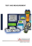
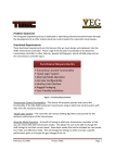
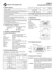
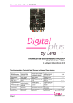
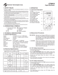
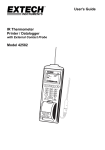
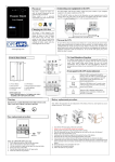
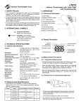
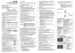
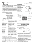
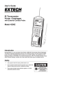
CT8027
General Technologies Corp.
Professional Automotive Digital Multimeter
1. SAFETY RULES
• This meter is designed for indoor use at temperatures between 0°C to 40°C and
•
•
•
•
•
•
•
•
•
altitudes up to 2,000m.
To ensure that the meter is used safely, follow all safety and operating instructions in
this operation manual. If the meter is not used as described in this operation manual,
the safety features of this meter might be impaired.
Do not use the meter if the meter or test leads look damaged ,or if you suspect that
the meter is not operating properly.
When using the instrument, keep your fingers behind the finger guards on the plastic
casing and probes.
Disconnect the live test lead before disconnecting the common test lead.
Make sure power is off before cutting, desoldering, or breaking the circuit wires. Small
amounts of current can be dangerous.
Do not apply more than 600 VDC or 600V AC rms between a terminal and ground.
To avoid electrical shock, use CAUTION when working above 60V DC or 25V AC rms.
Such voltages pose a shock hazard.
Never make measurements with the battery cover off.
To avoid electrical shock or damage to the meter, do not exceed the input limits.
Function
Dangerous Voltages
Continuity
Ground
Double Insulation
3.2 Electrical Specifications
0.5%+2
999.9 kΩ,
4.000 MΩ
0.8%+2
40.00 MΩ
1.5%+5
Diode Test
9.999 V
-
< 3.5 V Test Voltage
600 Vrms
Frequency
999.9Hz to
20.0 kHz
0.01%+2
1, 2, 20 and 200 Vrms
Selectable threshold
600 Vrms
Resistance
Fuel
Injector
0.05 - 250 mS
0.05mS+1
0.0 - 100 %
0.04%/krpm +2
0.05 - 250 mS
0.05mS+1
0.0 - 100 %
0.04%/krpm/cyl +2
Tachometer
60-10000 RPM
0.3%+3
DC Voltage
999.9 mV,
9.999 V,
99,99V
600 V
0.3%+5
999.9 mV
2.5%+5
AC Voltage
DC Current
AC Current
9.999 mV,
99.99 V
2.5%+5
4000 mA
1.2%+6
10.00 A
0.8%+4
4000 mA
2.5%+10
10.00 A
1.2%+3
Remarks
Overload
Protection
10 MΩ,
16MΩ for
999.9 mV
range
-
600 Vrms
10 MΩ,
16MΩ for
999.9 mV
range
0.03V/A
Burden
Voltage
0.03V/A
Burden
Voltage
600 Vrms
600 Vrms
RPM 2M
0.0º - 360.0º
1.2º/krpm+1
0.0º - 100.0º
0.04º/krpm/cyl +2
-20º to 300ºC
3ºC+1
301º to 500ºC
2%+1
0º to 572ºF
6ºF+2
573º to 932ºF
2%+2
1 to 12
Cyl.
600 Vrms
K-Type Thermocouple
Probe
600 Vrms
4. OPERATION
4.1 Instrument Description
1) Case
2) 4 Digit LCD display
3) Secondary Functions Button
4) Auto/Manual Select
5) Function Switch
6) Current Measurment Input
7) Common Input
8) Measurements Input
9) Trigger and Rel. Button
10) Hold and Max/Min. Button
1
2
3
4
10
9
5
8
6
±5°C, less than 75% RH. For DC/AC current measurement, the maximum current of 10 A is for 30 Sec. with 5 min. cool down between measurements.
Input
Impedance
RPM 2
30-5000 RPM
Dwell
Selectable
+/- Slope,
and
Number of
Cylinders
RPM 4
2 RPM
• Accuracies are ±(% of reading + number of least significant digits) at 23°C
Accuracy
600 Vrms
9.999 kΩ,
99.99 kΩ
Temperature
4 digits LCD, max. of 9999 display
Automatic, (-) negative polarity indication
Automatic
0.25 Sec., 0.05 Sec. for bar graph
“OL” is displayed
9-volt battery type NEDA 1604, IEC6F22
Approx. 70 hours. (w/ alkaline batteries)
5.9”x2.95”x1.34” or 150x75x34 mm.
Approx. 8.9 Oz. or 252g (with battery).
User’s Manual, Test Leads, Protective
Holster, Hard carriying case, K-type
temperature probe, Inductive pick-up and
9V battery.
Range
-
1.3 V
Max. Test
Voltage
(2.7 V in
999.9Ω
range)
0.5%+6
120-20000 RPM
3.1 General Specifications
Function
Overload
Protection
999.9Ω
3. TECHNICAL SPECIFICATIONS
Display:
Polarity:
Zero adjustment:
Sample rate:
Over range indication:
Power:
Battery life:
Dimension:
Weight:
Accesories:
Remarks
Accuracy
2. INTERNATIONAL SYMBOLS
Important information
see manual
AC
DC
Input
Impedance
Range
7
4.2 Display Description
Autoranging
Hold
Digital
Readout
Low Battery
Auto Power Off
50~200Hz
50~500Hz
600 Vrms
-
10 A - 250V
Fast Acting
Fuse
-
10 A - 250V
Fast Acting
Fuse
Record
Function
Relative
Measurement
Max./Min.
and Average
Bar Graph/Trigger Polarity
Analog
Bar Graph
Bar Graph
Overflow
4.3 Measurement Procedures
CAUTION: Maximum Input Voltage is 600Vrms,do not exceed
this rating to avoid personal injuries or damage to the
instrument. The FUNCTION switch should be set to
the range you want to test before the operation.
CAUTION: Always ensure that the correct terminals are used
for the type of measurement to be made. Avoid
making connections to “live” circuits whenever
possible.When making current measurements ensure that the circuit is not “live” before opening it in
order to connect the test leads.
Measuring
resistance
and
continuity
• The measurement will be shown in the LCD Display when the
probe are connected. For Continuity Test a continuous beeping
sound indicates that the measured resistance is < 100 Ω.
4.3.4 Frequency measurement
• Connect the black test lead to the “COM” socket and red test lead
•
•
•
•
•
Measuring
Voltages
4.3.1 DC/AC Voltage measurement
• Connect the black test lead to the “COM” socket and red test lead
to the “+” socket.
• Set the FUNCTION switch to the “ V Hz” function.
• The instrument default to DC measurement. To measure AC
Voltages press the SELECT button momentarily.
to the “+” socket.
Set the FUNCTION switch to the “ V Hz” function.
The instrument default to VDC measurement. To measure
frequency press the SELECT button momentarily twice, and the
Hz will appear on the display.
Connect the read probe into the “+” input and the black probe
into the “COM” input.
When the frequency function is selected, the trigger level defaults
to 1 Volt. If the readings are unstable or if there is not reading at
all, it maybe be necesary to change the trigger level. To change
the trigger level, press the “RANGE” button once to display the
selected level, and then press the “RANGE” button within 1
second. Every time the button is pressed the trigger level will
change to the next value (1V, 2V, 20V and 200V).
Connect the test leads across the source or circuit under
measurement. Readout will show on the LCD display.
4.3.5 Tach (RPM) Measurement
Taking Tach
Readings
• Connect the read probe into the “+” input and the black probe
into the “COM” input.
• Connect the test leads across the source or load under
measurement. Readout will show on the LCD display.
4.3.2 DC Current measurement
• Connect the black test lead to the “COM” socket and red test lead
to the “A mA” input connector. .
• Set the FUNCTION switch to the “mA A ” function.
• Connect the test leads in series with the source or load under
measurement.
• The instrument default to DC measurement. To measure AC
Current press the SELECT button momentarily.
• Connect the test leads in series with the source or load under
measurement. Readout will show on the LCD display.
4.3.3 Resistance measurement and Continuity Test
CAUTION: Maximum Input Voltage for this function is 600 Vrms
do not exceed this rating to avoid personal injuries or
damage to the instrument. Also ensure there is no
power applied to the component or circuit and all
capacitors are discharged.
• Connect the black test lead to the “COM” socket and red test lead
to the “+” socket.
• Set the FUNCTION switch to the “Ω ” position. The instrument
will default to Resistance measurement, to select the Continuity
Test function press the “SELECT” button momentarily.
• Connect the test leads across the componet or circuit under
measurement.
• Connect the black lead plug of the inductive pick-up into the
“COM” socket and red lead plug to the “+” socket.
position.
• Set the FUNCTION switch to the
Press
the
SELECT
button
to
select
through “RPM
•
” for 4
strockes, “RPM ” for 2 strockes and DIS, and “RPM M” for 2
strockes with waste spark ignition system engines.
• Open the Inductive Pick-up clamp and insert a spark plug wire
inside, observing that the arrow on the Inductive Pick-up points
to the spark plug, and then close the clamp making sure that the
clamp jaws are completely close. The RPM will be shown in the
LCD Display when the engine is running.
4.3.6 Dwell Angle Measurement
• Connect the black test lead to the “COM” socket and red test lead
to the “+” socket.
%” position, and press
• Set the FUNCTION switch to the “
the SELECT button once to select the
Dwell function.
The
Number
of
cylinders
defaults
to
4
(4-\).
Press the “Cylinder
•
/RANGE” switch to display the cylinders setting, and immediately
press the button again to select the number of cylinders (1
through 12) of the engine under test.
4.3.8 Temperature Measurement
• Set the FUNCTION switch to the “ ” position.
• The instrument defaults to ºC units, to select ºF units press the
Measuring
Dwell
• Connect the black test lead to the vehicle ground or negative (-)
terminal of the battery, and the red test lead to the breaker point of
the distributor or negative (-) terminal of the ignition coil.
• To display Dwell as a percentage (%), press the “SELECT” button
once. To display reading in degrees again, press the “SELECT”
button twice.
• To change the trigger level and slope please refer to Section 4.4.4
and 4.4.5 of this manual.
“SELECT” button once. To return to ºC units press the “SELECT”
button twice.
• Connect the K-type thermocouple probe connector into the “COM”
and “+” sockets observing the polarity of the connector and
socket.
• Make contact between the thermocouple at the end of the
probe the object to measure. To obtain accurate temperature
measurements, the contact between the probe and the object to
measure should be maintained for a few seconds until the readout
on the display becomes stable.
Measuring
Temperature
�����������
�����
������� �����
�����������
4.3.7 Fuel Injector (Pulse Width) Measurement
4.4 Other Functions
4.4.1 Diode Test
CAUTION: Maximum Input Voltage for this function is 600
Vrms, do not exceed this rating to avoid personal
injuries or damage to the instrument.
• Connect the black test lead to the “COM” socket and red test lead
to the “+” socket.
• Set the FUNCTION switch to the “
” position. The instrument
will default to temperature measurement in ºC units, to select
(diode test) press the “SELECT” button twice.•
• Forward voltage drop test: Connect the test leads across the
Measuring
Pulse Width on
EFI
systems
diode observing the polarity: red probe to the anode (+) of the
diode and black test lead to the cathode (-) of the diode under test.
The readout of a good silicon diode should be between 0.4 to 0.9
V. A readind outside this range may indicate a defective diode.
• Reverse Voltage test: Connect the test leads across the diode
• Connect the black test lead to the “COM” socket and red test lead
to the “+” socket.
%” position, the
• Set the FUNCTION switch to the “
instrument default to
, with units in ms (milliseconds).
• Connect the black test lead to the signal wire terminal of the fuel
injector, and the red test lead to the positive supply wire terminal of
the fuel injector.
• To display pulse width as a percentage (%) or duty cycle, press
the “SELECT” button twice. To display reading in ‘ms’ units again,
press the “SELECT” button again.
• This function applies to both Port Fuel Injectors (PFI) and Throttle
Body Injectors TBI). To change the trigger level and slope please
refer to Section 4.4.4 and 4.4.5 of this manual.
observing the polarity: red probe to the Catode (-) of the diode and
black test lead to the anode (+) of the diode under test. A diode in
good condition should produce a “OL“ reading, other reading may
indicate a damaged or defective diode.
4.4.2 Manual and Autoranging Operation
• To lock the present range, press the “RANGE” button once, and
the
display indicator will turn off. Pressing the “RANGE” button
will step through the ranges. Pressing and holding the “RANGE”
button for 1 second or more will restore the meter to autorange
mode.
• NOTE: When the instrument is in Record, Hold or Relative mode,
pressing the “RANGE” button will cause the meter to exit these
operations.
5. MAINTENANCE
4.4.3 Relative measurements
• Pressing the “REL ” button once enter the relative measurement
mode. In this mode the instrument offsets all the following
measurements with the value present at the time the relative mode
was entered.
• The relative mode can be used conmbined with any other function,
including MAX, MIN, MAX-MIN and AVG readings of the RECORD
function.
• Pressing the “REL
” button again exits this function.
CAUTION: Before attempting battery removal or replacement,
disconnect test leads and remove the instrument from
any energized circuit to avoid shock hazard.
5.1 Battery Replacement
• To replace the battery, remove the 3 screws of the back cover (back
of the case), and lift the end of the case nearest to the input sockets,
until it unsnaps from the case top. Remove the battery.
• Replace with a new 9 V alkaline battery type NEDA 1604 or IEC6F22
4.4.4 Trigger Level selection
• When measuring Frequency, Dwell or Pulse Width, and the
readings are unstable or if there is not reading at all, it maybe be
necesary to change the trigger level.
• To change the trigger level, press the “RANGE” button once to
display the selected level, and then press the “RANGE” button
within 1 second. Every time the button is pressed the trigger level
will change to the next value (1V, 2V, 20V and 200V).
observing the proper polarity from the diagram on the label inside
the battery compartment.
• Reinstall the case cover, ensuring that all gaskets are properly
seated, and that the snaps on the case top (near the LCD Display)
are engaged. Replace and tighten the securing screws.
4.4.5 Trigger Slope selection
• The slope function is useful when performing Dwell and Pulse
Width (Fuel Injector) measurements. For example, if you are
measuring a signal with 10% duty cycle when the trigger is set
to +, the same waveform will show a duty cycle of 90% when the
trigger is set to .
• To Toggle between Trigger + and , press and hold the + Trigger
(REL
) for 1 second or more.
5.2 Fuse replacement
4.4.6 Hold Display Data
• Pressing the “HOLD” button, will toggle the hold display funcion on
and off.
• When the HOLD function is activated, the readout on the display
will be maintained or ‘freezed’ until the function is turned off by
pressing the “HOLD” button again.
4.4.7 Record Mode
• Pressing the “REC ” button for 1 second or more will activate the
RECORD mode, and the
indicator will appear in the display.
• When the RECORD function is activated, the instrument will beep
when a new maximum or minimum is detected.
• To read the MAX, MIN, MAX-MIN and AVG, press the REC
button to step through the recorded measurements.
• Pressing the “REC ” button again for 1 second or more will exit
the RECORD mode.
• To replace the fuse, remove the 3 screws of the back cover (back of
the case), and lift the end of the case nearest to the input sockets,
until it unsnaps from the case top.
• Replace new fuse only with the identical type and rating.
F2=10A:
Type IEC60127-2 or UL248-14 (6.3x25.4mm)
fast acting fuse, rated at 10A/250V.
• Reinstall the case cover, ensuring that all gaskets are properly
seated, and that the snaps on the case top (near the LCD Display)
are engaged. Replace and tighten the securing screws.
5.3 Cleaning And Storage
• Periodically wipe the case with a soft damp cloth and mild household cleanser. Do not use abrasives or solvents. Ensure that no
water gets inside the instrument to prevent possible shorts and
damage.
• If the instrument is not to be use for long periods of time ( 60 days or
4.4.8 Auto Power Off
• This function is included to extend the battery life when the
instrument is not in use.
• The instrument will turn OFF automatically and sound a warning
beep, after approxiamtely 4 minutes of no activity (i.e. rotary
switch or buttons operations, or no significant meter reading
changes), .
• The instrument is turned automatically ON if the FUNCTION
more) to avoid damage due to battery leakage, remove the battery
from the instrument and store it separately.
6. WARRANTY
One year limited warranty, excluding batteries and fuses. For details see Standard Warranty Information in our webpage or request
a printed copy.
switch is operated.
4.4.9 External power lines noise filtering
• When the RECORD function is activated, the instrument will turn
off the AUTO POWER OFF function, and the
display will not show.
indicator in the
• To read the MAX, MIN, MAX-MIN and AVG, press the REC
button to step through the recorded measurements.
• Pressing the “REC
the RECORD mode.
” button again for 1 second or more will exit
General Technologies Corp.
#121 - 7350 72nd Street
Delta, BC
Canada V4G 1H9
Tel.: (604) 952-6699
Fax: (604) 952-6690
www.generaltechnologies.net
© Copyright 2001 General Technologies