1
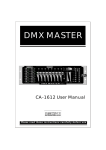
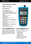
TC-253B
Temperature Converter
User Manual
Limited Warranty and Limitation of Liability
Your Amprobe product will be free from defects in material and workmanship for
1 year from the date of purchase. This warranty does not cover fuses, disposable
batteries or damage from accident, neglect, misuse, alteration, contamination,
or abnormal conditions of operation or handling. Resellers are not authorized
to extend any other warranty on Amprobe’s behalf. To obtain service during the
warranty period, return the product with proof of purchase to an authorized
Amprobe Test Tools Service Center or to an Amprobe dealer or distributor. See
Repair Section for details. THIS WARRANTY IS YOUR ONLY REMEDY. ALL OTHER
WARRANTIES - WHETHER EXPRESS, IMPLIED OR STAUTORY - INCLUDING IMPLIED
WARRANTIES OF FITNESS FOR A PARTICULAR PURPOSE OR MERCHANTABILITY, ARE
HEREBY DISCLAIMED. MANUFACTURER SHALL NOT BE LIABLE FOR ANY SPECIAL,
INDIRECT, INCIDENTAL OR CONSEQUENTIAL DAMAGES OR LOSSES, ARISING FROM
ANY CAUSE OR THEORY. Since some states or countries do not allow the exclusion
or limitation of an implied warranty or of incidental or consequential damages, this
limitation of liability may not apply to you.
EXPLANATION OF SYMBOLS
�
�
�
Attention! Refer to Operating instructions.
Ground connection.
Battery.
WARNING AND PRECAUTIONS
This instrument is designed to use external K-type thermocouple as temperature
sensor.
• Temperature indication follows National Bureau of Standards and IEC 584
temperature / Voltage tables for K-type Thermocouple supplied with the
thermometer.
• Inspect DMM, TC-253B, and thermocouple cable before every use. Do not use any
damaged part. nNever ground yourself when taking measurements.
• Do not touch exposed circuit elements or probe tips.
• Do not operate instrument in an explosive atmosphere.
• Voltages applied to the COM connector may be present on all other input
connectors.
• Do not use this piece or any piece of equipment without proper training.
� WARNING!
• TO AVOID ELECTRICAL SHOCK, DO NOT USE THIS INSTRUMENT WHEN VOLTAGES
AT THE MEASUREMENT SURFACE EXCEED 24V r.m.s. AC OR 60V DC.
• TO AVOID DAMAGE OR BURNS – DO NOT MAKE TEMPERATURE MEASUREMENTS
IN MICROWAVE OVENS.
UNPACKING AND INSPECTION
Upon removing your new Temperature Converter from its packing, you should
have the following items:
1. Temperature Converter
2. K-type Bead Thermocouple
3. Operator’s Manual
FRONT PANEL
Refer to Figure 1 and the following numbered steps to familiarize yourself with the
meter’s front panel controls and connectors.
1. Red LED: Flashing while turned ON.
2. Function Switch: Slide switch used to select measuring function.
3. Output plugs: Voltage output.
4. Thermocouple Input Connector.
Figure 1
4
3
2
1
PREPARATION AND CAUTION BEFORE MEASUREMENT
1. Before measurement, warm up for at least 30 seconds, after connecting the
thermocouple to the connector of the Temperature Converter.
2. If the instrument is used near noise generating equipment, be aware that the
Voltage output may become unstable or indicate large errors.
3. Check TC-253B battery. The multimeter should read > 7.1 volts in the OFF
position.
TEMPERATURE MEASUREMENTS
1. Warning! do not measure the temperature of any surface that the potential
exceeds 60 Vdc or 24 Vrms.
2. Connect the plug of the thermocouple to the connector of the thermometer.
3. Select the ºC/ºF function desired.
4. Insert the “Output Plugs (V and COM)” to the input terminals of Multimeter.
Set the Multimeter to “DC mV or V” range.
5. Place the sensing point of thermocouple on the surface or environment to be
measured.
6. Wait until the reading stabilizes.
GENERAL SPECIFICATIONS
This Temperature Converter conforms to the temperature/voltage tables of the
National Bureau of Standards and to the IEC 584 Standards for K-type.
1. Temperature Scale: Celsius or Fahrenheit user selectable.
2. Input: Single K-type thermocouple.
3. Output to Meter: 1mVdc per ºC or ºF.
4. Measurement Range: -50ºC to 1000ºC – (-58ºF to 1832ºF).
5. Low Battery Indication: if the reading is less than 7.1V.
6. Temperature Coefficient: 0.15 x (specified accuracy) / ºC, (<18ºC or >28ºC).
7. Power Requirements: Standard 9V battery, NADA 1604, JIS 006P, or IEC6F22 Size.
8. Battery Life: Alkaline 300 hours.
9. Dimensions: 122mm(L) x 46mm(W) x 30mm(D).
10. Weight (including battery): 114 grams.
11. Accessories: K-type bead thermocouple, battery (installed), operators
�
EMC: This product complies with requirements of the following European
Community Directives: 89/336/EEC (Electromagnetic Compatibility) as amended by
93/68/EEC (CE Marking). Directive73/23/EEC (Low Voltage) does not apply to this
product. However, electrical noise or intense electromagnetic fields in the vicinity
of the equipment may disturb the measurement circuit. Measuring instruments will
also respond to unwanted signals that may be present within the measurement
circuit. Users should exercise care and take appropriate precautions to avoid
misleading results when making measurements in the presence of electronic
interference.
ENVIRONMENTAL CONDITIONS:
1. Indoor Use.
2. Operating Ambient: 0% to 80% R.H. (0 to 35 ºC); 0% to 70% (35 to 50ºC) R.H.
3. Storage Temperature: -20 to 60ºC, 0 to 80% R.H. with battery removed from
Temperature Converter.
ELECTRICAL SPECIFICATIONS:
MEASUREMENT RANGE
-50ºC
-19ºC
ACCURACY
-20ºC
=(2.0% rdg + 2ºC)
350ºC
=(0.5% rdg + 2ºC)
C 500ºC
=(2.0% rdg + 2ºC)
1000ºC
=(2.9% rdg + 2ºC)
-58ºF
-4ºF
=(2.0% rdg + 4ºF)
-3ºF
662ºF
=(0.5% rdg + 4ºF)
663ºF
932ºF
=(2.0% rdg + 4ºF)
933ºF
1832ºF
=(2.9% rdg + 4ºF)
351º
501ºC
INPUT PROTECTION
60Vdc & 24Vrms
ACCESSORIES:
TP-255A Replacement Bead Probe
TP-254A Immersion Probe with Handle
MH101KA Master Handle Probe
TP110KA Immersion Probe *
TP120KA Surface Probe *
TP130KA Air Probe *
*(TP110KA, TP120KA, & TP130KA require MH101KA Handle)
TP-255A Bead Thermocouple:
Temperature Range: -40ºC to 204ºC (-40ºF to 400ºF).
Tolerances: = (2.2ºC or 0.75%) from 0ºC to 204ºC
= (2.2ºC or 2.0%) from 0ºC to -40ºC
Wire Length: 1 meter, with miniature plug. Teflon tape insulated.
MAINTENANCE:
�WARNING!
TO AVOID ELECTRICAL SHOCK REMOVE TEST
THERMOCOUPLE BEFORE OPENING THE COVER.
GENERAL MAINTENANCE:
1. The case can be cleaned with a mild solution of detergent and water. Apply
sparingly with a soft cloth and allow the TC-253B to dry completely before using.
Do not use hydro carbon or chlorinated solvents or abrasives for cleaning.
2. All calibration and repair should be performed by an authorized service center or
by other qualified instrument service personnel. To maintain a thermocouple in
good condition, observe the following items.
• Avoid excess bending.
• Don’t overheat the thermocouple.
• Avoid chemical reactions that can damage the thermocouple.
BATTERY CHECKING AND REPLACEMENT:
To check the battery:
1. Turn the TC-253B OFF.
2. Insert the “output plugs (V and COM)” to the input terminals of multimeter to
“DCV” for autoranging type meter or 20 VDC or greater for manual ranging
type meter.
3. Read the display on the multimeter. Replace the battery, if the reading is less
than 7.1V.
To replace the battery, refer to Figure 2 and use the following procedure.
1. Turn the TC-253B OFF and disconnect the multimeter and thermocouple.
2. Position the TC-253B face down. Remove the screw from the bottom case.
3. Remove the bottom case.
4. Carefully disconnect the battery from bottom case
Figure 2
Battery 9V
Screw
REPAIR
Read the warranty located at the front of this manual before requesting
warranty or nonwarranty repairs. For warranty repairs, any multimeter claimed
to be defective can be returned to any authorized Amprobe Distributor or to a
Amprobe Service Center for an over-the-counter exchange for the same or like
product. Nonwarranty repairs should be sent to a Amprobe Service Center. Please
call Amprobe or inquire at your point of purchase for the nearest location and
current repair rates. All Instruments returned for warranty or non-warranty repair
or for calibration should be accompanied by the following information or items:
company name, customer’s name, address, telephone number, proof of purchase
(warranty repairs), a brief description of the problem or the service requested, and
the appropriate service charge (for non-warranty repairs). Please include the test
leads with the meter. Service charges should be remitted in the form of a check, a
money order, credit card with expiration date, or a purchase order made payable
to Amprobe or to the specific service center. For minimum turn-around time on
out-of-warranty repairs please phone in advance for service charge rates. The
Temperature converter should be shipped with transportation charges prepaid to
one of the addresses/service centers shown on the rear cover.
Manual Revision Date 05/07
Manual Part Number 1564694
Information contained in this manual is
proprietary to Amprobe and is provided
solely for instrument operation and
maintenance. The information in this
document may not be duplicated in any
manner without the prior approval in
writing from Amprobe. Specifications
subject to change.
© Amprobe, 2007
U.S. Service Center
Amprobe
Everett, WA 98203
Tel: (877) 956-2680
Fax: 425-446-6390
Canadian Service Center
Amprobe
400 Britannia Rd. E.Unit #1
Mississauga, ON L4Z 1X9
Tel: (905) 890-7600
Fax: (905) 890-6866