1
Archived 4/2/10
HI-4456
Isotropic Electric Field Probe
User's Manual
Copyright © 1999 by Holaday Industries, Inc.
Manual #600075
2/00
$12.50
Archived 4/2/10
Revision Record
Manual #600075
HIn4456 Isotropic Electric Field Probe
Revision
--A
B
C
D
Description
Release
Added CE Label
Revised
Changed Charger Specs
Changed Area Code
Date
8/97
10/97
1/98
8/99
2/00
Archived 4/2/10
TABLE OF CONTENTS
1.0 DESCRIPTION . . . . . . . . . . . . . . . . . . . . . .
Introduction . . . . . . . . . . . . . . . . . . . . . . .
1
1
2.0 HIn4456 SPECIFICATIONS . . . . . . . . . . . .
3
.
.
.
.
.
.
.
.
.
.
.
.
.
.
.
.
.
.
.
.
.
.
.
.
.
.
.
.
.
.
.
.
.
.
.
.
.
.
.
.
.
.
.
.
.
.
.
.
.
.
.
.
.
.
.
.
.
.
.
.
.
.
.
.
.
.
.
.
.
.
.
.
.
.
.
.
.
.
.
.
.
.
.
.
.
.
.
.
.
.
.
.
.
.
.
.
.
.
.
.
.
.
.
.
.
.
.
.
.
9
.
9
.
9
. 10
5.0 MAINTENANCE . . . . . . . . . . .
Introduction . . . . . . . . . . . . . .
Maintenance Recommendations
Upgrade Policies . . . . . . . . . . .
Return Procedures . . . . . . . . . .
Periodic/Preventive Maintenance
Parts Information . . . . . . . . . .
.
.
.
.
.
.
.
.
.
.
.
.
.
.
.
.
.
.
.
.
.
.
.
.
.
.
.
.
.
.
.
.
.
.
.
.
.
.
.
.
.
.
.
.
.
.
.
.
.
.
.
.
.
.
.
.
.
.
.
.
.
.
.
11
11
11
11
11
12
13
.
.
.
.
.
.
.
.
.
.
.
.
.
.
.
.
.
.
.
.
.
.
.
.
.
.
.
.
.
.
.
.
.
.
.
.
.
.
.
.
.
.
.
.
.
.
.
.
.
.
.
.
.
.
15
15
15
17
18
18
3.0 ACCEPTANCE AND CONTROLS
Introduction . . . . . . . . . . . . . .
Unpacking and Acceptance . . .
Probe . . . . . . . . . . . . . . . . . .
XMIT/RCV . . . . . . . . . . .
ARM/OFF . . . . . . . . . . . .
CHARGER . . . . . . . . . . . .
Battery . . . . . . . . . . . . . . . . .
4.0 BATTERY CHARGING
Introduction . . . . . . .
Charging Procedure . .
Battery Tips . . . . . . .
.
.
.
.
.
.
.
.
6.0 THEORY OF OPERATION
Introduction . . . . . . . . .
System Theory . . . . . . .
Probe Operation . . . . . .
Probe Power Supply . . .
Zeroing . . . . . . . . . . . .
.
.
.
.
.
.
.
.
.
.
.
.
.
.
.
.
.
.
.
.
.
.
.
.
.
.
.
.
.
.
.
.
.
.
.
.
.
.
.
.
.
.
.
.
.
.
5
5
5
5
5
6
6
7
Archived 4/2/10
7.0 APPLICATION CONSIDERATIONS
Introduction . . . . . . . . . . . . . . .
Out-of-Band Considerations . . . .
Resolution Limitations . . . . . . . .
Probe Support Structures . . . . . .
.
.
.
.
.
.
.
.
.
.
.
.
.
.
.
.
.
.
.
.
.
.
.
.
.
.
.
.
.
.
.
.
.
.
.
.
.
.
.
.
21
21
21
21
21
APPENDIX A
ERROR CODES . . . . . . . . . . . . . . . . . . . . . . . . . 23
Probe Error Output . . . . . . . . . . . . . . . . . . 23
APPENDIX B
HIn4456 OPERATING PROTOCOLS
Introduction . . . . . . . . . . . . .
Communication Protocol . . . .
Information Transfer Protocol .
Command Structure . . . . . . .
Commands . . . . . . . . . . . . . .
Probe Output . . . . . . . . . . . .
.
.
.
.
.
.
.
.
.
.
.
.
.
.
.
.
.
.
.
.
.
.
.
.
.
.
.
.
.
.
.
.
.
.
.
.
.
.
.
.
.
.
.
.
.
.
.
.
.
.
.
.
.
.
.
.
.
.
.
.
.
.
.
.
.
.
.
.
.
.
25
25
25
25
25
26
28
Archived 4/2/10
Limited Warranty
Holaday Industries, Inc. warrants each model HIn4456 Isotropic
Electric Field Probe to be free from defects in material and
workmanship for a period of one year from the date of shipment
to the purchaser. This warranty extends to the original purchaser
only, and does not apply to the batteries or to any products or
parts subject to misuse, neglect, accident, unauthorized service
or abnormal conditions of operation.
In the event an instrument covered by this warranty fails,
Holaday Industries, Inc. will, without charge, repair and
recalibrate the instrument if returned to their factory within one
year of the original purchase-provided that Holaday Industries'
examination discloses, to its satisfaction, that the product is
defective. Holaday Industries, Inc., may, at its option, replace
the product in lieu of repair. If the defect was caused by misuse,
neglect, accident, unauthorized service or abnormal conditions of
operation, repairs will be billed at a nominal cost. In such cases,
an estimate will be provided before work is started, if requested
by the purchaser.
For warranty service, contact Holaday Industries, Inc. Provide
the serial number of the instrument and complete details
regarding the failure mode. You will then be given either service
information or shipping instructions. Return the instrument to
the factory, transportation prepaid. Repairs will be made at the
factory and the instrument will be returned to you, transportation
prepaid. Holaday Industries, Inc., assumes no responsibility for
loss of, or damage to, products in transit.
Warning!
EXTREME CAUTION IS ADVISED WHEN WORKING IN
ENVIRONMENTS WHERE HIGH-INTENSITY ELECTROMAGNETIC
FIELDS MAY EXIST AND WHERE CONTACT WITH HIGH VOLTAGE
OR HIGH CURRENT CIRCUITS OR APPARATUS IS POSSIBLE.
ACCIDENTAL CONTACT WITH OBJECTS OR CIRCUITS OPERATING
AT HIGH VOLTAGES OR HIGH CURRENTS CAN BE LETHAL!
HOLADAY INDUSTRIES, INC. ASSUMES NO LIABILITY FOR ANY
DAMAGES OR PERSONAL INJURY WHICH MAY RESULT FROM
Archived 4/2/10
HIn4456 Manual
Page — 1
1.0 DESCRIPTION
Introduction
The HI-4456 RF Electric Field probe is a broadband
isotropic sensor suitable for a wide range of
RF/microwave measurements. While the HI-4456 is
suited for many types of measurements within its
frequency range, it is primarily designed for measuring
pulsed fields such as are found in radar applications. The
thermal sensor elements respond accurately to a wide
range of signal waveforms, providing a true RMS
representation of the field waveform.
Applications include: health and safety monitoring, radar
transmitting antennas, and measuring any type of RF
pulsed radiation. The HI-4456 probe is optically isolated
to minimize field perturbation during measurements.
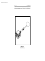
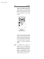
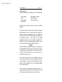
The HI-4456 probe assembly consists of a spherical
casing, containing the sensor, which is mounted on one
end of a shaft; the other end of the shaft is attached to
an extrusion which houses the electronics (Figure 1n1).
The sensor and electronics housing operate - and are
calibrated - as a unit.
The HI-4456 sensor consists of three mutually orthogonal
(perpendicular) electric field sensors. The electric field
components in each of these directions are summed as
vectors and the resultant field value (magnitude)
transmitted via the fiber optic cable to the receiver (HI4416 System Readout or HI-4413G RS-232 Computer
Interface).
The frequency response of the HI-4456 extends from
300 MHz to 18 GHz. Extended frequency calibration
points are available up to 40 GHz.. The dynamic range
Archived 4/2/10
HIn4456 Manual
Page — 2
of the probe extends from 0.3 mW/cm2 to 265 mW/cm2.
Figure 1n1
HIn4456 Probe
Archived 4/2/10
HIn4456 Manual
2.0
Page — 3
HIn4456 SPECIFICATIONS
Dynamic Range:
0.3 to 265 mW/cm2
Ranges:
100, 300, 1 000 Volts/meter full
scale
Frequency
Response:
300 MHz to 1 GHz +0, -3 dB
1 GHz to 18 GHz ± 1.5 dB
18 GHz to 40 GHz +0, -6dB
Linearity:
± 0.5 dB full scale (F.S.): ± 2 least
significant bits (LSBs) of A/D
converter
Isotropicity:
300 MHZ to 18 GHz ± 1.2 dB
18 GHz to 40 GHz ± 2 dB
Peak Overload:
30 W/cm2
Pulse Energy
Density Overload:
150 W-µsec/cm2
Environmental:
Operating
Temperature:
Humidity:
Fiber Optic Cable
Connectors:
Battery:
10 °C to 40 °C (50 °F to 104 °F)
5% to 95% relative humidity, noncondensing
Standard FSMA
3.6 VDC, 1400 mA-h rechargeable
Nickel-Cadmium (NiCd)
Archived 4/2/10
HIn4456 Manual
Page — 4
Battery Charger:
115/230 VAC, approximately 1 hour
Battery Life:
17 Hours continuous (full charge)
Probe Mount:
¼ n 20 UNC tapped hole (internal
thread) in base of probe
Size:
Length (including
electronics housing): 419 mm (16.5 in)
Probe diameter:
76 mm (3.0 in)
Weight:
Optional Equipment:
0.54 Kg (19 oz.)
See Table 5n2
Archived 4/2/10
HIn4456 Manual
Page — 5
3.0 ACCEPTANCE AND CONTROLS
Introduction
This section contains information on: unpacking and
acceptance of the HIn4456; probe controls; probe
connectors; the battery, and the battery charger.
Unpacking and Acceptance
Step 1. Upon delivery of your order, inspect the
shipping container(s) for evidence of damage.
Record any damage on the delivery receipt
before signing. In case of concealed damage
or loss, retain the packing materials for
inspection by the carrier.
Step 2.
Remove the probe from its shipping
containers. Save the boxes and any protective
packing materials for future use.
Step 3.
Check all materials against the packing list to
verify that the equipment received matches
that which was ordered. If you find any
discrepancies, note them and call Holaday
Customer Service for further instructions.
Be sure that you are satisfied with the contents of your
order and the condition of your equipment before
installing the probe.
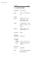
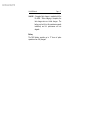
Probe
A switch, two fiber optic connectors and a battery
charger connector are mounted on the HIn4456
electronics housing (Figure 3n1).
XMIT/RCV
The fiber optic cable assembly from the
receiver is attached to the probe via two
Archived 4/2/10
HIn4456 Manual
Page — 6
connectors. The cables are color-coded-white
for XMIT, yellow for RCV. Identically-colored
dots are located on the electronics housing
adjacent to these connectors. Be sure that
each cable is attached to the proper probe
connector.
Figure 3n1
Switch and Connectors
When the fiber optic cables are not attached,
always cover the probe connectors with the
protective plastic covers supplied with the
unit, or with similar material. This prevents
dirt or other contaminants from entering the
connector and causing communication
problems.
ARM/OFF
The
ARM/OFF
switch
activates
and
deactivates the probe. In the ARM position,
the probe is powered by its internal 3.6 VDC
NiCd battery: in the OFF position, the probe is
inactive. To prolong battery life, set the
ARM/OFF switch to OFF at the end of a test
sequence or when the probe is not in use.
Archived 4/2/10
HIn4456 Manual
CHARGER
Page — 7
A standard fast charger is supplied with the
HIn4456. When charging is complete, the
fast charger acts as a trickle charger. The
battery can be left on this maintenance mode
indefinitely and it’s performance will not
degrade.
Battery
The NiCd battery provides up to 17 hours of probe
operation when fully charged.
Archived 4/2/10
Page — 8
HIn4456 Manual
Archived 4/2/10
HIn4456 Manual
Page — 9
4.0 BATTERY CHARGING
Introduction
Each HIn4456 probe contains a rechargeable nickelcadmium (NiCd) battery. A fully-charged battery (nominal
output voltage of 3.6 VDC) provides up to 17 hours of
continuous operation.
NOTE
Holaday Industries, Inc., charges the internal NiCd battery
of the HIn4456 at the factory in order to calibrate the
probe prior to shipment. While every effort is made to
ensure that your probe arrives ready to use, we cannot
guarantee that this will be the case. Always check the
condition of the probe's battery prior to making any
measurements. To check probe battery voltage, refer to
the operation of the BAT keypad in Section 8.0 of the
HIn4416 User's Manual.
Charging Procedure
Step 1. Plug the charger into a suitable AC source.
Step 2.
Set the probe switch to OFF. Insert the plug
on the charger cable into the probe's
CHARGER jack.
Step 3.
The battery is now charging. This may take
approximately 1 hour, depending on how
deeply the batteries are discharged. When
charging is complete, the charger
automatically goes into a trickle charge and
will continue to do so until the probe is
disconnected.
Archived 4/2/10
Page — 10
HIn4456 Manual
Battery Tips
NiCd batteries have several characteristics that can affect
both their performance and operating life. The following
tips advise you how to take advantage of these
characteristics to get the most out of your probe’s
battery.
Although NiCd batteries are rated for operation in
temperatures from -20 °C to +65 °C (-4 °F to +140
°F), operating the probe in extreme temperatures will
reduce operating time significantly.
The optimum
operating temperature range for these batteries is +20
°C to +30 °C (+68 °F to +86 °F).
The battery in the HIn4456 probe does not require
periodic "deep discharges" to reverse the capacitydepleting "memory effect" caused by repeated shallow
discharges; however, undercharging can reduce battery
capacity. Therefore, after the charging procedure is
complete, be sure that the battery is fully charged before
resuming field operation.
If the battery exhibits low terminal voltage during
charging, or if it appears unable to acquire or maintain an
appreciable charge, individual cells in the battery may be
shorted or damaged. If, for any reason, your battery
needs replacement, contact Holaday Customer Service for
assistance.
Archived 4/2/10
HIn4456 Manual
5.0
Page — 11
MAINTENANCE
Introduction
This section explains which maintenance tasks can be
performed by the user. It also provides information
regarding replacement and optional parts. If you have
any questions concerning probe maintenance, consult
Holaday Customer Service.
Maintenance Recommendations
Maintenance of the HIn4456 probe is limited to external
components such as cables or connectors.
Any calibration or maintenance task which requires probe
disassembly should be performed at the factory. Check
with Holaday Customer Service (952-934-4920) before
opening the unit to avoid problems with your probe's
warranty.
NOTE
Opening the probe enclosure may void your warranty. If
your system is still under warranty, contact Holaday
Customer Service before performing any maintenance
inside the probe.
Upgrade Policies
Periodically, probes are upgraded to enhance
functionality. These upgrades are commonly announced
through Holaday Engineering Bulletins.
Return Procedures
To return a probe to Holaday, use the following
procedures:
Step 1.
Briefly describe the problem in writing. Give
Archived 4/2/10
HIn4456 Manual
Page — 12
details regarding the observed symptom(s),
and whether the problem is constant or
intermittent in nature. If you have talked
previously to Holaday Customer Service about
the problem, provide the date(s), the name of
the service representative you spoke with, and
the nature of the conversation. Include the
serial number of the item being returned.
Step 2.
The sensor and electronics housing are
engineered to operate as a unit and MUST be
returned together. Carefully package the
probe assembly in the carrying case. Use the
original boxes and packing materials, if
possible. If not, use the Parts List in Table
5n1 to order new boxes and foam packing
from Holaday Industries, Inc.
NOTE
If your probe is calibrated in accordance with MIL-Std45662A, it is greatly to your benefit to retain the original
shipping box and packing materials. One of the criteria
for certifying a calibration to MIL standards requires
Holaday Industries to always ship equipment in the
specified packaging. When a MIL Standard instrument is
sent to Holaday in other packaging, we must replace it
with the specified packaging materials for return
shipment.
YOU WILL BE BILLED FOR THE NEW
PACKAGING.
If the probe is under warranty, refer to the Limited
Warranty at the front of this manual for additional
information about your return.
Periodic/Preventive Maintenance
The HIn4456 probe assembly (sensor and electronics
Archived 4/2/10
HIn4456 Manual
Page — 13
housing) require an annual calibration check to verify that
they are performing within specifications. This calibration
check may be performed at the factory by Holaday
Service Personnel. Return your probe(s), using the
original packing materials (if possible), to:
Holaday Industries Inc.
Attn. Service Department
14825 Martin Drive
Eden Prairie, MN USA 55344
Parts Information
Use the following tables for ordering replacement (Table
5n1) or optional (Table 5n2) parts for HIn4456 probes.
Table 5n1
Replacement Parts List
Part Description (Replacement
Parts)
Battery Pack, 3.6 VDC,
Rechargeable
Part Number
491038
Standard Fast Charger (115/230
Volt)
491198-36
Cable, Fiber Optic, Glass, 2 Meter
490994-02
Handle Assembly
491073
HIn4456 User's Manual
600075
Archived 4/2/10
HIn4456 Manual
Page — 14
Table 5n2
Optional Parts List
Part Description (Optional Parts)
Part Number
Probe Support, HIn4456
490984
Tripod, Dielectric, HIn4456
491000
Fiber Optic / RS232 Interface
HIn4413G
Archived 4/2/10
HIn4456 Manual
Page — 15
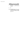
6.0 THEORY OF OPERATION
Introduction
This section discusses the theory of operation and the
functions of the HIn4456 Isotropic Electric Field Probe.
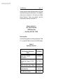
A high-level block diagram (Figure 6n1) is included to aid
the discussion. The objective is to provide information
that enhances user understanding of the design of this
probe.
System Theory
The HI-4456 Broadband Isotropic Electric Field Probe uses
three orthogonal thermal sensing elements. Each of the
elements responds to the electric field component aligned
with the particular element. The output of each element
is proportional to the RMS value of the field component.
The output of the three elements are summed as vector
quantities and an output proportional to the resultant field
generated.
A microprocessor is contained in the instrumentation
housing located at the base of the probe shaft. The
microprocessor generates an output corrected for
variations in the sensor using lookup tables located in the
processor memory. The resultant value is transmitted in
an ASCII digital format through the optical cable to the
readout.
The probe's self-contained power supply
employs a 3.6 VDC NiCd battery which provides up to 17
hours of continuous operation. Refer to Appendix B for
details of the ASCII output formats.
For specialized applications, you may use a computer
with an RS-232 serial port to communicate directly with
the HI-4456 using the optional HI-4413G RS-232
interface.
Archived 4/2/10
HIn4456 Manual
Page — 16
Figure 6n1
Probe Block Diagram
Archived 4/2/10
HIn4456 Manual
Page — 17
Probe Operation
Receiver commands to the probe consist of the following:
Send reading
Zero
Switch range
Enable axis
Read battery voltage
Set sleep timer
Read temperature
The signal flow within the probe is shown in the block
diagram.
To measure field strength, three mutually orthogonal
dipole antennas (one per axis) are used to provide an
isotropic response to the ambient field. The signal from
each axis is fed to a Schottky diode detector operating in
its Square-Law region.
After filtering, the signals
generated by each axis are added vectorially: the
resultant is fed to the instrumentation amplifier, whose
output feeds the selectable range/offset stage.
NOTE
The HIn4456 does not allow the option of measuring on
an individual axis: all three axes are active at all times.
Consequently, the axis keypads on the front panel of the
HIn4416 System Readout have no effect when an
HIn4456 is connected to it.
For each of the four ranges, the selectable range and
offset stage provides a coarse analog zero for the
measured signal. The output of the range/offset stage is
fed to the A/D multiplexer, then to the analog-to-digital
(A/D) converter itself.
After acquiring the composite three-axis signal, the
microprocessor commands the A/D multiplexer to read
the battery voltage and temperature sensing lines.
Archived 4/2/10
HIn4456 Manual
Page — 18
Data from the A/D converter is fed to the microprocessor,
which transmits it to the receiver.
The EEPROM stores all calibration data for the probe.
Probe Power Supply
The HIn4456 probe is powered by a sealed rechargeable
3.6 VDC NiCd battery, which drives both the analog and
digital power supplies: separate power sources provide
isolation between the analog and digital circuitry. With
the probe switch in the ARM position, battery voltage is
applied to the power switch, which routes this voltage to
the power supply, enabling the microprocessor. The
power switch is controlled by a timer circuit. The timer
monitors the fiber optic connector input line to determine
whether the probe has received a command during a
specified period (several seconds). If no command is
received during this period, the timer signals the power
switch to disable the power supply and the
microprocessor. In essence, the probe goes dormant to
conserve battery power: only the fiber optic input
circuitry remains active in order to detect new
commands. When the next command from the receiver
reaches the probe, power is reapplied automatically and
the processor is reactivated, "waking up" the probe.
NOTE
The probe uses volatile random access memory (RAM).
If, for any reason, power to the probe is lost, the probe
must be re-zeroed.
Zeroing
When the receiver sends a zero command, the probe
must be in a zero field environment. This is because the
zero command causes the multiplexer (via the processor)
to perform a normal read cycle on the composite axis
signal. This procedure is executed for all ranges. When
Archived 4/2/10
HIn4456 Manual
Page — 19
the processor receives all the zero-field values, it stores
them in a special register; these values are subtracted
from all subsequent measurements. Therefore, a probe
which is zeroed while it is not in a zero field environment
will give erroneous readings.
Archived 4/2/10
Page — 20
HIn4456 Manual
Archived 4/2/10
HIn4456 Manual
Page — 21
7.0 APPLICATION CONSIDERATIONS
Introduction
The following subsections contain information designed
to help you maximize the effectiveness of the HIn4456.
Out-of-Band Considerations
Although the HIn4456 is nominally rated for operation
from 300 MHz to 18 GHz, it may respond to signals both
above and below these frequencies. Such responses
must be taken into account when performing certain
operations, such as zeroing.
On the lower end, the HIn4456 can exhibit significant
response to frequencies below 300 MHz. Such out-ofband responses may pose a problem when zeroing the
unit, since that operation assumes a zero field condition.
At the upper end, similar problems may occur.
Resolution Limitations
Limitations in probe resolution may result in a non-zero
reading when the receiver is zeroed. If this occurs, it
does not necessarily mean either that there is a problem
with the receiver or that your readings are inaccurate.
Receiver linearity is specified as + 0.5 dB full scale: in
addition, the variance of the A/D converter is + 2 least
significant bits. When using the most sensitive range on
a given probe, these specifications create the possibility
that, under zero field conditions, the receiver may display
a non-zero value.
Probe Support Structures
It is very important to keep conductive objects away from
the HIn4456. Any such objects in the proximity of the
probe may distort the near field and compromise
measurement accuracy. If your application requires
Archived 4/2/10
Page — 22
HIn4456 Manual
measurements from a fixed position, always mount the
probe on a non-metallic platform, using non-metallic
screws.
Archived 4/2/10
HIn4456 Manual
Page — 23
APPENDIX A
ERROR CODES
Probe Error Output
If an error occurs, the probe will respond with one of the
following strings. These strings begin with a colon and
end with a carriage return.
E01
Communication error (e.g., overflow).
E02
Buffer full error.
Too many characters
contained between the Start Character/
Carriage Return sequence.
E03
The received command is not valid.
E04
The received parameter is not valid.
E05
Hardware error (e.g., EEPROM failure).
E06
Parity error.
Archived 4/2/10
Page — 24
HIn4456 Manual
Archived 4/2/10
HIn4456 Manual
Page — 25
APPENDIX B
HIn4456 OPERATING PROTOCOLS
Introduction
The information in this appendix assumes that you have
purchased the optional HIn4413G Fiber Optic / RS232
Interface, and are capable of communicating directly with
the HIn4456 probe via computer. No system readout is
required when using this configuration.
Communication Protocol
Data Type:
Data Mode:
Word Length:
Parity:
Stop Bits:
Data Rate:
RS-232 Serial
Asynchronous
7 bit
Odd
1
9600 baud
Information Transfer Protocol
The HIn4456 operates as a Controller Mode device. This
probe only responds to commands from another device;
it transmits no data without first receiving instructions to
do so.
Command Structure
A command to an HIn4456 probe consists of 1) a
command letter, followed by 2) possible parameters, 3)
terminated with a carriage return. When it completes the
command, the probe responds with a string consisting of
1) a start character (":"), 2) the command letter, followed
by 3) data, if required, and terminated with 4) a carriage
Archived 4/2/10
HIn4456 Manual
Page — 26
return. If the command does not require the probe to
return any data, the probe simply responds with the
command letter and a carriage return. If an error occurs,
the probe responds with an error code, as detailed in
Appendix A.
Commands
Command
Description
B
Read battery voltage.
Cx
Set baud rate.
x = 1 sets rate to 2400 baud
x = 2 sets rate to 9600 baud
New baud rate does not take effect until the next
power-up.
Dx
Read probe data.
x = 1 enables short form output
x = 2 enables long form output
Lx
Load table data. x = ASCII hex data
Rx
Set range. x = 1, 2, 3, 4 or N (next range)
Sx
Sleep timer. x = number of seconds to wait for
a command before putting probe into the sleep
mode.
Tx
Read Temperature. x = C or F
Ux
Set unit type. x = 1, 2, 3, or N (next unit)
1 = V/m
2 = mW/cm²
3 = [V/m]²
Archived 4/2/10
HIn4456 Manual
Page — 27
Vtx
Verify table data. t = table (same table as for Lx
command, above). x = number of bytes to send
in one string.
Z
Zero.
Null
Send the ASCII null character. This is a special
command that can be used as the initial command
to the probe after it is powered up. The probe
responds with “N”.
Archived 4/2/10
HIn4456 Manual
Page — 28
Probe Output
Command
HIn4456 Response
B
Bxx.xx, where xx.xx is the battery voltage.
D1
Dxx.xxuuu, the short form output.
xx.xx is the reading. The position of the decimal
point depends upon the range setting of the
probe.
uuu = units
_V_ = V/m, mW2 = mW/cm², _V2 = [V/m]²
(underscore indicates a space character)
D2
Dxx.xxuuurrrobaaat, the long form output.
xx.xx = the reading, as described for D1.
uuu = units, as describe for D1.
rrr = recorder out value (A 3-digit ASCII number
from 0 to 255).
o = over range indicator ("N" = ok, "O" = over
range).
b = battery status ("N" = safe operating level,
"W" = warning level, "F" = fail level).
aaa = axis enable ("E" = enabled).
t = terminating carriage return.
Rx
Rx, where x is the range.
x = "" returns the range currently in use
x = 1, 2, 3, 4 enables the selected range
x = N sets the probe to the next (higher) range.
Archived 4/2/10
HIn4456 Manual
Page — 29
TF
Txxx, where xxx is temperature in ° Fahrenheit.
TC
Txxx, where xxx is temperature in ° Centigrade.
Vtx
Vxx[xx...], where xx is table data in ASCII hex.
Archived 4/2/10
HIn4456 Manual
Page — 30
--NOTES--