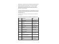
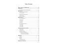
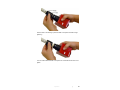
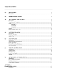
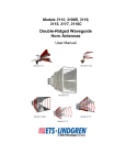
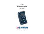
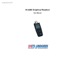
1
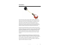
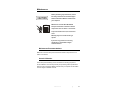
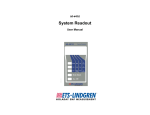
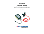
Model HI-4433
Broadband Isotropic
Field Probe
User Manual
This page intentionally left blank.
ii
|
ETS-Lindgren L.P. reserves the right to make changes to any product described
herein in order to improve function, design, or for any other reason. Nothing
contained herein shall constitute ETS-Lindgren L.P. assuming any liability
whatsoever arising out of the application or use of any product or circuit
described herein. ETS-Lindgren L.P. does not convey any license under its
patent rights or the rights of others.
© Copyright 1993–2009 by ETS-Lindgren L.P. All Rights Reserved. No part
of this document may be copied by any means without written permission
from ETS-Lindgren L.P.
Trademarks used in this document: The ETS-Lindgren logo is a trademark of
ETS-Lindgren L.P.
Revision Record | HI-4433 Series Probe, MANUAL | Part #600056, Rev. K
Revision
Description
Date
Initial Release
October, 1993
A
Revised
September, 1994
B
Revised
June, 1995
C
Added Probes
September, 1995
D
Revised
August, 1996
E
Changed Charger
October, 1997
F
Added CE Label
October, 1997
G
Revised
January 1998
H
Changed Charger Specs
August, 1999
I
Changed Area Code
February, 2000
J
Revised
August, 2005
|
iii
Revision
Updated branding: Revised to meet
Style Guide specifications;
reformatted to half-size; PIB
included with release
K
iv
Description
|
Date
March, 2009
Table of Contents
Notes, Cautions, and Warnings .............................................. vii Introduction ................................................................................ 9 ETS-Lindgren Product Information Bulletin ................................................. 10 Maintenance ............................................................................. 11 Maintenance Recommendations ................................................................. 11 Annual Calibration ....................................................................................... 11 Replacement and Optional Parts ................................................................. 12 Upgrade Policies .......................................................................................... 13 Service Procedures ..................................................................................... 13 Specifications ........................................................................... 15 General Specifications ................................................................................. 15 H-Field Probes ............................................................................................. 16 HI-4433-HCH ............................................................................................... 16 HI-4433-LFH ................................................................................................ 16 HI-4433-CH .................................................................................................. 17 E-Field Probe Specifications ........................................................................ 17 HI-4433-STE ................................................................................................ 17 HI-4433-GRE ............................................................................................... 18 HI-4433-MSE ............................................................................................... 18 Practical Application and Use ................................................ 19 System Theory ............................................................................................. 19 Automatic Zero ............................................................................................ 19 Probe Power Supply .................................................................................... 20 Application Considerations .......................................................................... 20 HI-4416 Hand Held Readout ............................................................... 21 HI-4413P Fiber Optic Interface ............................................................ 22 Operation .................................................................................. 23 Xmit/Rcv ...................................................................................................... 23 ARM/OFF ..................................................................................................... 24 Charger ........................................................................................................ 24 Assembling the Probe .................................................................................. 26 Appendix A: Warranty ............................................................. 29 |
v
Appendix B: EC Declaration of Conformity .......................... 31 Appendix C: Series H-491198-36 Battery Charger for NiCd
Batteries .................................................................................... 33 Safety Precautions ....................................................................................... 33 Introduction .................................................................................................. 33 Battery Life ................................................................................................... 34 Charging a Battery ....................................................................................... 34 Specifications ............................................................................................... 36 Maintenance Recommendations ................................................................. 37 Appendix D: HI-4433 Operating Protocols ............................ 39 vi
|
Notes, Cautions, and Warnings
Note: Denotes helpful information intended to
provide tips for better use of the product.
Caution: Denotes a hazard. Failure to follow
instructions could result in minor personal injury
and/or property damage. Included text gives proper
procedures.
Warning: Denotes a hazard. Failure to follow
instructions could result in SEVERE personal injury
and/or property damage. Included text gives proper
procedures.
See the ETS-Lindgren Product Information Bulletin for safety,
regulatory, and other product marking information.
|
vii
This page intentionally left blank.
viii |
Introduction
The HI-4433 series comprises a family of battery-operated broadband radio
frequency (RF) isotropic field probes designed for use in making RF exposure
measurements in the vicinity of broadcast facilities and industrial RF sources.
These probes use optical isolation to minimize field perturbation during
measurements. Each probe in this series has characteristics that optimize its
performance for a particular application. Model number differentiates individual
probes for example HI-4433-XXX, where XXX defines the specific probe.
Each HI-4433 series probe assembly consists of a spherical casing containing
the sensor mounted on one end of a shaft. The other end of the shaft is attached
to an extrusion that houses the electronics. The sensor and electronics housing
operate, and are calibrated, as a unit. Since the appearance and layout of the
electronics housing are the same for all probes in this series, both the probe
assembly and the housing are coded with identical serial numbers to prevent
mismatch.
HI-4433 series probes measure the field strength in each of three axes. They
perform a vector addition calculation on the readings and send the result to the
readout via a fiber optic cable. Data from each axis can be viewed individually, or
can be combined. The measurement capability and frequency response of
HI-4433 series probes depend upon which model is selected. In addition, both
magnetic and electric field probes are available.
Introduction
|
9
ETS-Lindgren Product Information Bulletin
See the ETS-Lindgren Product Information Bulletin included with your shipment
for the following:
10
•
Warranty information
•
Safety, regulatory, and other product marking information
•
Steps to receive your shipment
•
Steps to return a component for service
•
ETS-Lindgren calibration service
•
ETS-Lindgren contact information
|
Introduction
Maintenance
Before performing any maintenance, follow
the safety information in the ETS-Lindgren
Product Information Bulletin included with
your shipment.
WARRANTY
Maintenance of the HI-4433 Broadband
Isotropic Field Probe is limited to external
components such as cables or connectors.
To prevent electrical shock, do not remove
cover.
Warranty may be void if the housing is
opened.
If you have any questions concerning
maintenance, contact ETS-Lindgren
Customer Service.
Maintenance Recommendations
Maintenance of the HI-4433 probe is limited to external components such as
cables or connectors.
Annual Calibration
The HI-4433 probe assembly (sensor and electronics housing) requires an
annual calibration check to verify that they are performing within specifications.
See the Product Information Bulletin included with your shipment for information
on ETS-Lindgren calibration services.
Maintenance
|
11
Replacement and Optional Parts
Following are the part numbers for ordering replacement or optional parts for the
HI-4433 Broadband Isotropic Field Probe.
Replacement Parts
Part Description
Part Number
Battery Pack, 3.6 VDC,
H-491038
Rechargeable
Standard Fast Charger (115/230
H-491198-36
Volt)
Cable, Fiber Optic, Glass, 2 Meter
H-491106-xx (where “xx” = length”)
Probe Cover (2 required)
H-470286A
Handle Assembly
H-491001
HI-4433 User Manual
H-600056
Shipping Carton
H-390066
Optional Parts
Part Description
12
Part Number
Tripod, Dielectric, HI-4433
H-491009
Fiber Optic/RS232 Interface
HI-4413P
ProbeView EMF Analysis Software
ProbeView II
Digital Remote Readout
HI-4416
Carrying Case
H-491083
|
Maintenance
Upgrade Policies
Periodically, probes are upgraded to enhance functionality. Contact ETSLindgren Customer Service for the upgrade status of your probe.
Service Procedures
For the steps to return a system or system component to ETS-Lindgren for
service, see the Product Information Bulletin included with your shipment.
Maintenance
|
13
This page intentionally left blank.
14
|
Maintenance
Specifications
General Specifications
• Overall
Calibration Accuracy
+2/-3 dB*
• At calibration points
±0.5 dB*
*Absolute accuracy to NIST ± 1.0 dB
Isotropicity
± 0.5 dB
Linearity
±0.5 dB
• Operating Temp.
10ºC to 40ºC
(50º F to 104ºF)
Environmental
• Humidity
5% to 95%*
*relative humidity, non-condensing
Fiber Optic Cable
Connector
Standard FSMA
3.6 VDC, 14000mA-h rechargeable Nickel-
Battery
Cadmium (NiCd), 20 hours of continuous
operation
Battery Charger
Size
115/230 VAC, approximately 1 hour
• Length*
559mm (22.0 in.)
• Probe Diameter
102mm (4.0 in.)
• Weight*
0.57 kg (20 oz)
*Including electronics housing
Probe Mount
¼ - 20 UNC tapped hole (internal thread) in base
of probe
Specifications
|
15
H-Field Probes
HI-4433-HCH
Ranges
0.1, 0.3, 1.0, 3.0 A/m full scale
Frequency Response
5.0 MHz to 300 MHz
See General Specifications table for additional
information.
HI-4433-LFH
Ranges
1.0, 3.0, 10.0, 30.0 A/m full scale
Frequency Response
0.3 MHz to 30.0 MHz
See General Specifications table for additional
information.
16
|
Specifications
HI-4433-CH
Ranges
0.3, 1.0, 3.0, 10.0 A/m full scale
Frequency Response
5.0 MHz to 300 MHz
See General Specifications table for additional
information.
E-Field Probe Specifications
HI-4433-STE
Ranges
100, 300, 1000, 3000 V/m full scale
Frequency Response
0.5 MHz to 5.0 GHz
See General Specifications table for additional
information.
Specifications
|
17
HI-4433-GRE
Ranges
10, 30, 100, 300 V/m full scale
Frequency Response
0.5 MHz to 5.0 GHz
See General Specifications table for additional
information.
HI-4433-MSE
Ranges
30, 100, 300, 1000 V/m full scale
Frequency Response
0.5 MHz to 5.0 GHz
See General Specifications table for additional
information.
18
|
Specifications
Practical Application and Use
Before connecting any components, follow the
safety information in the ETS-Lindgren
Product Information Bulletin included with your
shipment.
System Theory
HI-4433 series Broadband RF Probes utilize a microprocessor for intelligent
operation and control. Their self-contained power supply employs a 3.6 VDC
NiCd battery, which provides up to 20 hours of continuous operation.
For each axis, the probe measures the radio frequency signal level and
generates a linearized reading of this measurement. A vector addition is
performed on these three readings: the resultant is transmitted to the readout
over glass fiber optic cables.
Receiver commands to the probe consist of the following:
•
•
•
Send reading
•
Set sleep timer
Read battery
•
Switch range
voltage
•
Read temperature
Zero
•
Enable axis
Automatic Zero
This feature eliminates the need for internal zero adjustment and eliminates the
temperature drift problems associated with other instrumentation. The automatic
continuous zero also allows the operator to use the meter immediately upon
power-up. Also, it is not necessary to place the meter in a zero field environment
to check its zeroing.
Practical Application and Use
|
19
In addition to the inputs from the three axes, HI-4433 series probes utilize a
fourth input called the Autozero channel. This is a redundant channel identical to
the three axis channels except that, instead of being driven by a dipole, it is
terminated (in the probe head) by a carbon resistor. This resistor simulates the
zero-bias impedance of the Schottky diode in series with the high resistance feed
line; it is also subject to the same temperature variations as the feed lines of the
other three channels.
Probe Power Supply
A sealed rechargeable 3.6 VDC NiCd battery, which drives both the analog and
digital power supplies, powers HI-4433 series probes; separate power sources
provide isolation between the analog and digital circuitry. With the probe switch
in the ARM position, battery voltage is applied to the power switch, which routes
this voltage to the power control and the switching power supply, enabling the
microprocessor. This power supply does not shut off automatically. Always turn
the power supply off when the probe is not in use.
Application Considerations
Resolution Limitations
Limitations in probe resolution may result in a non-zero reading
when the receiver is zeroed. If this occurs, it does not necessarily
mean either that there is a problem with the receiver or that your
readings are inaccurate. Receiver linearity is specified as + 0.5
dB full scale: in addition, the variance of the A/D converter is + 2
least significant bits. When using the most sensitive range on a
given probe, these specifications create the possibility that, under
zero field conditions, the receiver may display a non-zero value.
Probe Support Structures
It is very important to keep conductive objects away from the HI4433. Any such objects in the proximity of the probe may distort
the near field and compromise measurement accuracy. If your
application requires measurements from a fixed position, always
mount the probe on a non-metallic platform, using non-metallic
screws.
20
|
Practical Application and Use
Optional Probe Interface/Readout
The probe provides data to the readout via either a short form or
long form output word. Commands to the probe use these same
word forms. See Appendix B for details on the format for both out
put words.
HI-4416 HAND HELD READOUT
The HI-4416 provides a digital display and data logging
capabilities as well as optical isolation when a hand-held readout
is desired.
Practical Application and Use
|
21
HI-4413P FIBER OPTIC INTERFACE
For limited, specialized applications, you may use any computer
with an RS232 serial port to communicate directly with the
HI-4433 series probes via ETS-Lindgren’s optional HI-4413P
Fiber Optic/RS232 Interface.
22
|
Practical Application and Use
Operation
Before connecting any components, follow the
safety information in the ETS-Lindgren
Product Information Bulletin included with your
shipment.
A switch, two fiber optic connectors and a battery charger connector are mounted
on the HI-4433 electronics housings.
Xmit/Rcv
The fiber optic cable assembly from the
receiver is attached to the probe via two
connectors. The cables are color-coded:
white for XMIT, yellow for RCV. Identically
colored dots are located on the electronics
housing adjacent to these connectors.
Ensure that each cable is attached to the
proper probe connector.
When the fiber optic cables are not
attached, always cover the probe
connectors with the protective plastic
covers supplied with the unit, or with
similar material. This prevents dirt or
other contaminants from entering the
connector and causing communication
problems.
Operation
|
23
ARM/OFF
The ARM/OFF switch activates and
deactivates the probe. In the ARM
position, the probe is powered by its
internal 3.6 VDC NiCd battery: in the
OFF position, the probe is inactive. To
prolong battery life, set the ARM/OFF
switch to OFF at the end of a test
sequence or when the probe is not in
use.
Charger
Each HI-4433 probe contains a
rechargeable nickel-cadmium (NiCd)
battery. A fully-charged battery
(nominal output voltage of 3.6 VDC)
provides up to 17 hours of continuous
operation.
ETS-Lindgren charges the internal NiCd battery of the HI-4433 at the
factory in order to calibrate the probe prior to shipment. While every
effort is made to ensure that your probe arrives ready to use, we
cannot guarantee that this will be the case. Always check the
condition of the battery prior to making any measurements.
A standard fast charger is supplied with the HI-4433. When charging is
complete, the fast charger acts as a trickle charger.
24
|
Operation
Charging Procedure
Begin by plugging the charger into a suitable AC source. Next, set the
probe switch to OFF. Insert the plug on the charger cable into the
probe's CHARGER jack.
The battery is now charging. Charging may take approximately one
hour, depending on how deeply the batteries are discharged. When
charging is complete, the charger will automatically begin a trickle
charge and will continue to do so until the probe is disconnected.
Tips
NiCd batteries have several characteristics that can affect both their
performance and operating life. The following tips advise you how to
take advantage of these characteristics to get the most out of your
probe’s battery.
•
Although NiCd batteries are rated for operation in temperatures
from -20ºC to +65ºC (-4ºF to +140ºF), operating the probe in
extreme temperatures will reduce operating time significantly. The
optimum operating temperature range for these batteries is +20ºC
to +30ºC (+68ºF to +86ºF).
•
The battery in the HI-4433 probe does not require periodic deep
discharges to reverse the capacity depleting memory effect
caused by repeated shallow discharges; however, undercharging
can reduce battery capacity. Therefore, after the charging
procedure is complete, be sure that the battery is fully charged
before resuming field operation.
•
If the battery exhibits low terminal voltage during charging, or if it
appears unable to acquire or maintain an appreciable charge,
individual cells in the battery may be shorted or damaged. If, for
any reason, your battery needs replacement, contact
ETS-Lindgren Customer Service for assistance.
Operation
|
25
Assembling the Probe
Each HI-4433 series probe assembly consists of a spherical casing containing
the senor mounted on one end of a shaft and an extrusion that houses the
electronics. The sensor and electronics housing operate, and are calibrated, as a
unit. Since the appearance and layout of the electronics housing are the same
for all probes in this series, both the probe assembly and the housing are coded
with identical serial numbers to prevent mismatch.
To begin assembly, locate the probe and the corresponding probe housing.
Position the alignment arrows on the probe and housing so they are lined up, and
then gently press the probe into the housing.
26
|
Operation
Pull the collar on the housing up to the threads on the probe and twist to begin
tightening.
Turn the collar until the threads on the probe are covered. Be careful not to overtighten.
Operation
|
27
This page intentionally left blank.
28
|
Operation
Appendix A: Warranty
See the Product Information Bulletin included with your shipment for
the complete ETS-Lindgren warranty for your HI-4433 Broadband
Isotropic Field Probe.
DURATION OF WARRANTIES FOR HI-4433 BROADBAND ISOTROPIC FIELD
PROBE
All product warranties, except the warranty of title, and all remedies for warranty
failures are limited to one year.
Product Warranted
Duration of Warranty Period
HI-4433-xxx
1 Year
Warranty
|
29
This page intentionally left blank.
30
|
Warranty
Appendix B: EC Declaration of Conformity
EC Declaration of Conformity
|
31
This page intentionally left blank.
32
|
EC Declaration of Conformity
Appendix C: Series H-491198-36 Battery Charger
for NiCd Batteries
The HI-4422 Field Probe contains a Nickel Cadmium (NiCd) battery,
and uses the Series H-491198-36 Battery Charger.
SAFETY PRECAUTIONS
Before operating the Series H-491198-36 Battery
Charger, see General Safety Considerations on
page Error! Bookmark not defined..
INTRODUCTION
The H-491198-36 Nickel-Cadmium (NiCd)
Battery Charger is a dual power source
battery charger. It charges 3.6 volt 1400
mAH NiCd batteries and is powered by
120-240 VAC line power or 12.5 VDC. The
H-491198-36 Battery Charger uses a
-(dV)/(dT) negative delta V technique to
determine when the battery is fully charged,
which is typically one hour. With this
technique, the charge state of the battery
has no effect other than shortening the
charge time.
Housed in a rugged enclosure, power enters the battery charger through a power
entry module, which contains the fuses, or an optional cigarette lighter plug
adapter. The front face of the battery charger displays LEDs that provide the
operating status. The battery charger connects to the device being charged
through a short cord terminated with a power jack.
An integrated circuit within the battery charger monitors the battery voltage and
controls the charging functions according to the charge state of the battery.
Series H-491198-36 Battery Charger
|
33
BATTERY LIFE
A fully-charged battery (nominal output voltage of 3.6 VDC) provides up to 20
hours of operation. When the battery has discharged to 3.3 VDC, the Field Probe
is still operational, but the battery needs charging. When the voltage drops below
3.18 VDC, measurement accuracy will be compromised by further operation.
Follow these recommendations to ensure maximum battery life and optimum
testing performance:
•
Operate the Field Probe only within the optimum operating
temperature range of +20ºC to +30ºC (+68ºF to +86ºF). Although
NiCd batteries are rated for operation in temperatures from
-20ºC to +65ºC (-4ºF to +140ºF), operating the Field Probe at
temperature extremes reduces the operating time of the batteries.
•
Make sure the battery is fully charged before resuming operation. The
battery does not require periodic deep discharges to reverse the effect
caused by repeated shallow discharges, but undercharging can reduce
battery capacity.
If the battery exhibits low terminal voltages during charging, or if it appears
unable to acquire or maintain a charge, individual cells in the battery may be
shorted or damaged. If your battery needs replacement for any reason, contact
ETS-Lindgren Customer Service.
CHARGING A BATTERY
1.
Make sure the power switch on the Field Probe is set to the OFF
position or the battery will not charge.
2.
Connect the battery charger to the proper power source, and then
connect the charger to the charger jack on the Field Probe.
Charging takes approximately one hour, depending on the degree of
battery discharge. When charging is complete, the battery charger
automatically enters into a trickle charge, and continues until the Field
Probe is disconnected.
Never attempt to recharge a non-rechargeable
battery.
34
|
Series H-491198-36 Battery Charger
CHARGING INDICATORS
The following LEDs are located on the front of the battery charger:
•
POWER ON (green)—Indicates the battery charger is connected to the
AC power source.
•
NO BATTERY (amber)—Indicates the battery charger does not detect
a battery.
•
PENDING (amber)—Indicates the battery charger detects a battery.
Before fast charging can begin, the battery voltage must fall within
predetermined acceptable limits. A pulse-trickle charge is provided to
bring a depleted battery to a valid charge prior to fast charge.
•
CHARGING (amber)—Indicates the voltage pre-qualification condition
has been met, and fast charge has started.
•
COMPLETE (green)—Indicates a fast charging peak voltage is
detected. The Field Probe can remain connected to the battery charger
indefinitely while in this maintenance mode.
Series H-491198-36 Battery Charger
|
35
SPECIFICATIONS
BATTERY CHARGER SPECIFICATIONS
The H-491198-36 charger may be powered by standard line voltage (110 - 240
Vac, 50 - 60 Hz) or by an optional automobile cigarette lighter plug (12.5 Vdc).
Power
Main:
IEC filtered AC power input module
110-240 VAC, 500 mA max,
50-100 Hz
Alternate:
Automobile cigarette lighter to 2 mm
power plug adapter cord, 12.5 Vdc,
100 mA
Fuses:
250 volt, 1.0 Amp, Type T
(5 mm x 20 mm)
Output
Open Circuit Voltage:
15 Vdc
Fast Charge Pending Current:
60 mA
Fast Charge Current:
Pulsed Trickle Charge Current:
Output Voltage (During Fast
Charge):
NiMH Battery:
1400 mA
50 mA
3 - 6 Vdc
• 3.6 volt 3 cell NiCd Battery, 1400
mAH (rapid charge cells,
1.2 volts/cell)
• ETS-Lindgren Part #491038
36
|
Series H-491198-36 Battery Charger
Environmental
Operating Temperature:
10ºC to 40ºC
50ºF to 104ºF
Humidity:
5% to 95% relative humidity,
non-condensing
MAINTENANCE RECOMMENDATIONS
•
•
Operate the battery charger with care.
There are no user serviceable parts inside the battery charger.
Opening the battery charger housing may void your warranty.
REPLACING THE FUSE
Disconnect the battery charger from power
before replacing a fuse.
If the battery charger fails to operate, check for a blown fuse inside the power
entry module. A blown fuse must be replaced with the same value and type of
fuse, or an unsafe condition may result. Use only 250 Volt, 1.0 Amp, Type T
(5 mm x 20 mm) fuses.
To replace a fuse:
3.
Two fuses are located in the fuse drawer in the power input
module. Use a screwdriver to open the drawer.
4.
The fuse towards the outside of the drawer is the spare. Remove
the spare fuse from the module.
Series H-491198-36 Battery Charger
|
37
5.
Replace the blown fuse with the spare fuse.
6.
Slide the fuse drawer back into the module. Make sure that the
drawer snaps securely into its locked position.
38
|
Series H-491198-36 Battery Charger
Appendix D: HI-4433 Operating Protocols
The following information assumes that the optional HI-4413P Fiber Optic/RS232
Interface was purchased and is capable of communicating directly with an HI4433 probe via computer. No system readout is required when using this
configuration.
COMMUNICATION PROTOCOL
Data Type:
RS-232 Serial
Data Mode:
Asynchronous
Word Length:
7 bit
Parity:
Odd
Stop Bits:
1
Data Rate:
9,600 baud
INFORMATION TRANSFER PROTOCOL
The HI-4433 series probes only respond to commands from another device; they
transmit no data without first receiving instructions to do so.
COMMAND STRUCTURE
Probe
Description
Probe Response
Command
Axxx
Axis enable/disable.
• x=E (enable) or D
(disable)
• xxx order=X axis, Y
axis, Z axis
B
Read battery voltage.
Bxx.xx,
• xx.xx=battery voltage
Series H-491198-36 Battery Charger
|
39
Probe
Description
Probe Response
Command
Dx
Read probe data.
For D1 command:
• x=1, enables short form
output
output
• x=2, enables long form
output
Dxx.xxuuu, the short form
• xx.xx=the reading, and the
position of the decimal
point depends upon the
range setting of the Field
Probe
• uuu=units
• _V_ = V/m, mW2 =
mW/cm², _V2 = [V/m]²
(underscore indicates a
space)
For D2 command:
Dxx.xxuuurrrobaaa, the long
for output
• xx.xx=the reading, as
described for D1
• uuu=units, as described
for D1
• rrr=recorder out value, a
three-digit ASCII number
from 0 to 255
• o=over range indicator:
N=ok, O=over range
• b=battery status: N=safe
operating level,
W=warning level, F=fail
level
• aaa=axis enable:
E=enabled, D=disabled,
axis order=X, Y, Z
40
|
Series H-491198-36 Battery Charger
Probe
Description
Probe Response
Command
Rx
Set range.
Rx, where x is the range
• x=1, 2, 3, 4, or N (next
• x=returns the range
range)
currently in use
• x=1, 2, 3, 4 enables the
selected range
x=N sets the Field Probe to
the next higher range
Tx
Read temperature.
• x=C or F
For TF command:
Txxx
• xxx=temperature in
degrees in Fahrenheit
For TC command:
Txxx
• xxx=temperature in
degrees in Centigrade
Ux
Set unit type.
• x=1, 2, 3, or N (next
unit)
• 1=V/m
• 2=mW/cm²
• 3=[V/m]²
Z
Zero
Null
Send the ASCII null
This is a special command that
character.
can be used as the initial
command to the Field Probe
after it is turned on. The probe
responds with N.
Series H-491198-36 Battery Charger
|
41
PROBE ERROR OUTPUT
If an error occurs, the probe will respond with one of the following strings. These
strings begin with a colon and end with a carriage return.
E1
Communication error (for example, overflow)
E2
Buffer full error; too many characters contained between the
start character and carriage return sequence
42
E3
Received command is invalid
E4
Received parameter is invalid
E5
Hardware error (for example, EEPROM failure)
E6
Parity error
|
Series H-491198-36 Battery Charger