1
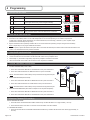
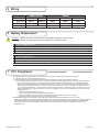
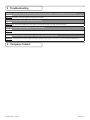
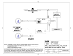
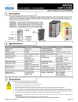
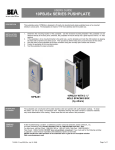
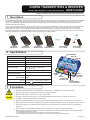
433MHz TRANSMITTERS & RECEIVER FCC ID#: G9B-10TD433HH4 IC ID#: 4680A-10TD433HH4 USER’S GUIDE DIGITAL TRANSMITTERS AND RECEIVER WITH SEQUENCING FUNCTION 1 Description The 433MHz Series Transmitters and Receiver are ideal for the wireless activation and/or sequencing of automatic doors. The transmitters are available in hand-held or pushplate styles and they transmit a unique rolling code each time the transmitter is activated (thus providing a secure door opening signal). The transmitter PN: 10TD433PB9V is powered by a 9-volt battery whereas all other transmitters are powered by a 3 volt battery and all illuminate a Red LED when activated. Since receivers can be individually programmed, multiple receivers can be programmed differently thus allowing for sequencing in multiple applications. Upon activation (pushplate / transmitter), all receivers will acquire the signal at the same time; however, each receiver will respond according to their programming. Those receivers programmed with NO DELAY will active immediately upon receiving the transmitter signal. Those receivers programmed with a DELAY will activate at the end of their pre-determined time delay set by the potentiometer. The use of multiple receivers will allow for the uninterrupted pace or hands free operations through a pair of doors upon initial activation. 10TD433HH ONE BUTTON 10TD433HH2 TWO BUTTON 10TD433HH3 THREE BUTTON 10TD433HH4 FOUR BUTTON 10TD433PB3V 3V w / LEADS 2 Specifications ANTENNA WIRE DESCRIPTION SPECIFICATION FREQUENCY 433 MHz EMITTED RADIO POWER -28.7 dBm (Transmitter) POWER CONSUMPTION 3mA (Transmitter) INPUT VOLTAGE 12 to 24 VAC/DC (Receiver) CONTACT RATING 1.0 A @ 30 VDC / 0.3 A @ 60 VDC 0.5 A @ 125 VAC OPERATING TEMPERATURE 14ºF TO 131ºF (-10ºC TO 55ºC) MAX No. OF PROGRAMMED UNITS PER RECEIVER 100 TRANSMITTERS LEDs BLUE LED RED LED 30mA (Receiver) Receiver Learn RED Relay Activation BLUE DIMENSIONS Transmitter Receiver CERTIFICATIONS 10TD433PB9V 9V w / LEADS TERMINAL STRIP 2 3/4” X 1 3/8” X 9/16” (70mm x 35mm x 14mm) 2 3/4” x 2 1/8” x 1” (70mm x 55mm x 25mm) FCC, IC, LEARN W/O DELAY BUTTON DIP SWITCH LEARN WITH DELAY BUTTON DELAY POTENTIOMETER (Time Adjustment) 3 Precautions This product IS NOT intended for use with Maglocks / Electric Strikes. Contact BEA, Inc. for further information. Shut off all power going to work area before attempting any wiring procedures. Maintain a clean & safe environment when working in public areas. To remain in compliance with Part 15.231, do not operate transmitter (hold down button ) for longer than 5 seconds. Constantly be aware of pedestrian traffic around the area. Always stop pedestrian traffic through the doorway when performing tests that may result in unexpected- reactions by the door. ESD: Circuit boards are vulnerable to damage by electrostatic discharge. Before handling ensure you dissipate your body’s charge. Always check placement of components before powering up so that moving parts will not catch any wires or cause damage to equipment. Ensure compliance with all applicable safety standards (i.e. ANSI A156.10 / 19) upon completion of installation. DO NOT attempt any internal repair of the components. All repairs and/or component replacements must be performed by BEA, Inc. Unauthorized disassembly or repair: 1. May jeopardize personal safety and may expose one to the risk of electrical shock. 2. May adversely affect the safe and reliable performance of the product resulting in a voided warranty. 75.5092.08 EN 20110217 Page 1 of 4 4 Programming ON Toggle Relay Press the transmitter once and the relay output is active indefinitely, press it again and the relay will de-energize indefinitely. #2 DESCRIPTION FUNCTION (Pulse Mode Only) OFF 0.5 sec Hold Time Relay will remain active 0.5 second after the loss of activation. ON 10 sec Hold Time Relay will remain active 10 seconds after the loss of activation. 1 2 1 2 0.5s l 10s Press the transmitter once and the relay will be active momentarily. ON In Toggle Setting (1-ON), the Hold Time is inactive. Either setting for #2 dip switch will have the same result. ON 1 2 ON 1 2 0.5s l 10s Pulse Relay PUL TOG OFF ON PUL TOG FUNCTION 0.5s l 10s DESCRIPTION 0.5s l 10s #1 PUL TOG DIP SWITCH SETTINGS PUL TOG 1 10 second Pulse Setting 0.5 second Pulse Setting 2 HAND HELD CONFIGURATION 1. Set dip switches on the receiver to the desired activation cycle (dip switch 1 -Toggle or Pulse and dip switch 2 - 0.5s or 10s hold). 2. Press either Learn w/Delay Button or Learn w/No Delay Button on the receiver depending on the activation requirements (If delay learn is selected, adjust potentiometer to counterclockwise limit, 0 second delay). After learn cycle is complete, adjust potentiometer to desired delay time (0-30 sec). 3. Depress transmitter button repeatedly until Blue LED on the receiver illuminates (indicating reception of signal from transmitter). 4. To test the system, depress transmitter button (Red LED on Transmitter will illuminate) and observe that the Blue LED illuminates on the receiver. This indicates that the relay has been activated. 3 PUSH PLATE CONFIGURATION 1. Before beginning, it is easiest to have already prepared the installation of the pushplate. 2. Connect the wires from the transmitter to the NO and COM contacts of the pushplates switch. 3. Follow Steps 1-4 (Hand-Held Configuration); depress the pushplate to activate the transmitter. 4. Attach the transmitter to the inside of the electrical box and complete the installation. 4 TYPICAL VESTIBULE APPLICATION A OUTSIDE TRANSMITTER (PUSH PLATE) NOTE: Repeat Steps 2-3 to program additional transmitters. INNER RECEIVER 1. Press Learn w/NO DELAY BUTTON on OUTER Receiver then press Transmitter 1. 2. Press Learn w/DELAY BUTTON on INNER Receiver then press Transmitter 1. 2 OUTER RECEIVER NOTE: Set Potentiometer to desired Delay Time per Hand Held Configuration Step #2. B INSIDE TRANSMITTER (PUSH PLATE) 1. Press Learn w/NO DELAY BUTTON on INNER Receiver then press Transmitter 2. 3 4 2. Press Learn w/DELAY BUTTON on OUTER Receiver then press Transmitter 2. 1 NOTE: Set Potentiometer to desired Delay Time per Hand Held Configuration Step #2. C VESTIBULE TRANSMITTERS (Dual Switch Pushplate or Two Separate Pushplates) 1. Press Learn w/NO DELAY BUTTON on INNER Receiver then press Transmitter 3. 2. Press Learn w/NO DELAY BUTTON on OUTER Receiver then press Transmitter 4. 5 REMOVING TRANSMITTER CODE(S) SINGLE TRANSMITTER CODE 1. Press both DELAY and NO DELAY BUTTONS simultaneously until Red LED flashes once (approximately 1 second). 2. Press transmitter button twice within 10 seconds and the transmitter code will be deleted. ALL TRANSMITTER CODES 1. Press and hold both DELAY and NO DELAY BUTTONS simultaneously until Blue LED illuminates then release (approximately 10 seconds). Page 2 of 4 75.5092.08 EN 20110217 5 Wiring Power VAC/DC Output Label 12 - 24 12 - 24 Com. N.O. N.C. Wire Color Red (+) Black (-) White Green Grey 1 2 Terminal Description Control or Transformer power 3 4 5 Control Common Control Activation Typically not used 6 Battery Replacement CAUTION: THERE IS A RISK OF EXPLOSION IF AN INCORRECT BATTERY TYPE IS USED. DISPOSE OF USED BATTERIES ACCORDING TO ITS INSTRUCTIONS. 1 3 - VOLT TRANSMITTERS 1. Remove two screws from back of transmitter. 2. Separate housing and install a fresh 3-Volt (Type CR2032) battery making sure to observe proper polarity. 3. Reassemble housing and replace screws. NOTE: Don’t throw used batteries away with the general trash. Discard per your local municipal laws and regulations. 2 9 - VOLT TRANSMITTER 1. Remove old battery. 2. Connect a fresh 9-Volt (Type 6LR61) battery making sure to observe proper polarity. NOTE: Don’t throw used batteries away with the general trash. Discard per your local municipal laws and regulations. 7 FCC Compliance FCC ID#: G9B-10TD433HH4 IC ID#: 4680A-10TD433HH4 • This Digital Transmitter complies with Part 15 of the FCC rules. Operation is subject to the following two conditions: 1) This device may not cause harmful interference and; 2) This device must accept any interference received including interference that may cause undesired operations. a) This equipment has been tested and found to comply with the limits for a Class B digital device, pursuant to part 15 of the FCC Rules. These limits are designed to provide a reasonable protection against harmful interference in a residential installation. This equipment generates, uses and can radiate radio frequency energy and, if not installed and used in accordance with the instruction, may cause harmful interference to radio communications. However, there is no guarantee that interference will not occur in a particular installation. If this equipment does cause harmful interference to radio or television reception, which can be determined by turning the equipment off and on, the user is encouraged to try to correct the interference by one or more of the following measures: • Reorient or relocate the receiving antenna. • Increase the separation between the equipment and receiver. • Connect the equipment into an outlet on a circuit different from that to which the receiver is connected. • Consult the dealer or an experienced radio/ TV technician for help. • This transmitter operates in the band 433.5- 434.5 MHz and is restricted to periodic transmissions of up to 5 seconds. • Changes or modifications not expressly approved by BEA, Inc. for compliance could void the user’s authority to operate the equipment. • Devices authorized under these provisions shall be provided with a means for automatically limiting operation so that the duration of each transmission shall not be greater than 60 seconds and be only permitted to re initiate an interrogation in the case of a transmission error. 75.5092.08 EN 20110217 Page 3 of 4 8 Troubleshooting Problem: THE RED LED ON MY RECEIVER IS JUST FLICKERING AND I’M UNABLE TO PROGRAM AND/OR IT WON’T WORK. Solution:You have a push plate stuck or faulty transmitter. Disconnect each push plate until the LED goes out. If LED does not go out, remove each transmitter battery until it does. Replace the appropriate transmitter. Problem: HOW DO I ERASE ONLY ONE TRANSMITTER CODE? Solution: Press both the delay and no delay buttons simultaneously on the receiver for approx. 1 second or until the red LED starts flashing on & off then release. Press the transmitter button twice within 10 seconds and the given transmitter code will be deleted. Problem: HOW DO I ERASE THE MEMORY ON THE 433 RECEIVER? Solution: Press both the delay and no delay buttons simultaneously on the receiver until the blue LED illuminates then release (aprox. 10 sec- onds). Problem: RECEIVER INTERMITTENTLY DOESN’T RECEIVE THE TRANSMITTER(S) SIGNAL. Solution: You may extend the receiver antenna wire only in multiples of 6.75” (6 3/4”). i.e. 6.75 x 4 = 27 inches of extended antenna wire 9 Company Contact 75.5092.08 EN 20110217 Page 4 of 4