1
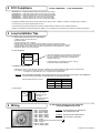
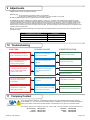
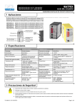
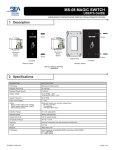
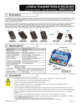
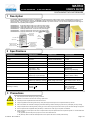
MATRIX FCC ID#: G9B-MATRIX USER’S GUIDE IC ID#: 4680A-MATRIX DIGITAL INDUCTIVE LOOP SENSORS 1 Description The MATRIX (10MATRIX) Digital Inductive Loop Detector is the ideal solution for parking barrier control, motorized gates and doors, vehicle access control and industrial control systems. The MATRIX is a high performance single or dual-channel vehicle detector packaged in a compact housing. The connection is made with a standard industrial 11-pin round connector. The six versions listed below include single or dual-channel, and 3 possible power supplies: 10MATRIXS110 : Single loop detector with 110 to 120 V AC power supply. 10MATRIXS220 : Single loop detector with 220 to 240 V AC power supply. 10MATRIXS1224 : Single loop detector with 12 to 24 V AC/DC power supply. 10MATRIXD110 : Dual loop detector with 110 to 120 V AC power supply. 10MATRIXD220 : Dual loop detector with 220 to 240 V AC power supply. 10MATRIXD1224 : Dual loop detector with 12 to 24 V AC/DC power supply. Presence Time Adjustment Potentiometer Main Connector (86CP11) Power LED Dip Switches Sensitivity Adjustment Potentiometer (Dual Loop Only) Detection State LED (Dual Loop Only) Sensitivity Adjustment Potentiometer Detection State LED BACK VIEW 2 Specifications TERMINOLOGY SPECIFICATION TERMINOLOGY SPECIFICATION TECHNOLOGY Inductive Loop POWER FREQUENCY 48 to 62 Hz TUNING Automatic POWER CONSUMPTION < 2.5 W DETECTION MODE Presence TEMPERATURE RANGE -22ºF to 158ºF (-30ºC to 70ºC) PRESENCE TIME 1 min to infinity with 250 steps DEGREE OF PROTECTION IP40 PULSE TIME OUTPUT 100 ms or 500 ms WEIGHT 7 oz. (<200g) LED INDICATORS Power: Green Loop Status 1: Red Loops Status 2: Red PROTECTIONS Loop Insulation Transformer Zener Diodes Gas Discharge Clamping FREQUENCY RANGE 20 kHz to 130 kHz INDUCTANCE RANGE 20 H to 1000 H FREQUENCY STEPS Single Loop: 4 Double Loop: 2 (for each loop) DIMENSIONS 3.0 in (H) x 1.5 in (W) x 3.0 in (D) (76mm x 38mm x 76mm) SENSITIVITY (ΔL / L) 0.005% to 0.5% with 250 steps CONNECTION 86CP11 (Standard 11-Pin Round) REACTION TIME Single Loop: 25ms Double Loop: 50ms (ea. channel) 2 OUTPUT RELAYS (free potential change-over contact) Max Contact Voltage: 230 VAC Max Contact Current: 5A (res.) SETUP TIME AFTER CONFIGURATION 2 s max by channel SETUP TIME AT POWER ON 8 s max by channel POWER SUPPLY (depending on model) 12-24 AC/DC + 10% 230 VAC + 10% 115 VAC + 10% PRODUCT COMPLIANCE R&TTE: 1999/5/EC EMC: 89/336/EEC FCC: 47 CFR 15 IC: RSS-210 ISSUE 5 3 Precautions Shut off all power before attempting any wiring procedures. Maintain a clean & safe environment when working in public areas. Constantly be aware of pedestrian traffic around the door area. Always stop pedestrian traffic through the doorway when performing tests that may result in unexpected reactions by the door. ESD: Circuit boards are vulnerable to damage by electrostatic discharge. Before handling any board ensure you dissipate your body’s charge. Always check placement of all wiring before powering up to insure that moving door parts will not catch any wires and cause damage to equipment. Ensure compliance with all applicable safety standards (i.e. ANSI A156.10 / A156.19) upon completion of installation. DO NOT attempt any internal repair of the sensor. All repairs and/or component replacements must be performed by BEA, Inc. Unauthorized disassembly or repair: 1. May jeopardize personal safety and may expose one to the risk of electrical shock. 2. May adversely affect the safe and reliable performance of the product will result in a voided product warranty. 75.1046.05 EN 20130710 Page 1 of 5 4 FCC Compliance FCC ID#: G9B-MATRIX IC ID#: 4680A-MATRIX 10MATRIXS110 : Single loop detector with 110 to 120 V AC power supply. 10MATRIXS220 : Single loop detector with 220 to 240 V AC power supply. 10MATRIXS1224 : Single loop detector with 12 to 24 V AC/DC power supply. 10MATRIXD110 : Dual loop detector with 110 to 120 V AC power supply. 10MATRIXD220 : Dual loop detector with 220 to 240 V AC power supply. 10MATRIXD1224 : Dual loop detector with 12 to 24 V AC/DC power supply. The Digital Transmitters and Receivers comply with Part 15 of the FCC rules. Operation is subject to the following two conditions: 1) This device may not cause harmful interference and; 2) This device must accept any interference received including interference that may cause undesired operations. Changes or modifications not expressly approved by BEA, Inc. for compliance could void the user’s authority to operate the equipment. 5 Loop Installation Tips A . CABLE SPECIFICATIONS FOR LOOP AND FEEDER • • • • • • • 16 AWG (1.5mm²) cross section area ; Multi-strand cable ; Insulation material : PVC or Silicone ; For the feeder cable, the wire must be twisted at least 15 times per yard for each cable. Feeder for long runs used for foil screened cable is recommended (earth at equipment end only) The feeder cable must be firmly fixed to avoid any false detection (max length: 330 ft. / 100m). Waterproof cable junction box is required. B. LOOP GEOMETRY L Ea • When two adjacent loops are connected to a dual channel sensor, it is possible for these loops to share a common slot, if so required. As the channels are multiplexed, no interference will occur. Eb • Avoid large loops or long feeder (max 330 ft. / 100 m), or else the sensitivity will be affected. C. NUMBER OF LOOP TURNS • Measure the length (L) and width (Ea) of one loop. Multiply these numbers together to determine the loop surface area. • For example: If L=10 ft, Ea= 3 ft, then the area = 30 ft2; 4 loop turns are recommended - or If L=2m, Ea=1m, then the area = 2 m2 ; 4 loop turns are recommended. WARNING: FOR CONFORMITY REASONS, IN ANY INSTALLATION, THE LOOP SURFACE MULTIPLIED BY THE NUMBER OF TURNS SHOULD NOT EXCEED 215 SQUARE FEET OR 20 SQUARE METERS. Recommended values for the turns: Area Number of turns <32 ft² <3 m² 4 32 – 54 ft² 3 – 5 m² 3 65 – 108 ft² 6 – 10 m² 2 D. SLOT DEPTH Ground level Loop sealant 1 ¼ - 2” (30 – 50mm) depending on the cable turns number Clean and dry slots prior to inserting cable 6 Wiring UL Requirement: Shall be used with suitable UL Recognized SWIV2 Relay Socket. PIN 1: Power Supply WARNING: PIN 2: Power Supply PIN 3: Relay 2 (NO) PIN 4: Relay 2 (COM) WARNING: PIN 5: Relay 1 (NO) PIN 6: Relay 1 (COM) PIN 7: Loop A PIN 8: Loop Common (Connect to Ground PIN 9: Loop B PIN 10: Relay 1 (NC) PIN 11: Relay 2 (NC) Page 2 of 5 DO NOT REMOVE THE GREASE ON THE CONNECTOR’S PINS. PIN #8 MUST BE CONNECTED TO THE LOOP AND TO GROUND. ) 75.1046.05 EN 20130710 7 Programming I. THE 3 CONFIGURATIONS A. Configuration A: Single Loop Detector (MATRIX-S) B. Configuration B: Dual Loop Detector in Independent Mode with Dipswitch #10 OFF (MATRIX-D) C. Configuration C: Dual Loop Detector in Combined Mode with Dipswitch #10 ON (MATRIX-D) Dip Switch Configuration A Single loop OFF ON DS#1 Configuration B Dual loop in independent mode OFF ON See next table High (loop A) Active mode Passive mode Active mode Low (loop A) [High –30%] Low (loop B) [High –30%] Passive mode Active mode Low (loop A) [High –30%] Low (loop B) [High –30%] Passive mode ASB OFF ASB ON ASB OFF ASB ON ASB OFF ASB ON Relay A : Presence on loop A Relay A : Pulse on loop A entry Relay B : Presence on loop A Relay B : Pulse on loop A entry 100 ms Relay A : Pulse on loop Relay A : Presence on loop A Relay A : Pulse on loop A Not used Not used Relay A : Pulse on loop A exit Relay A : Pulse on loop A entry Relay A : Pulse on loop A Exit Relay B : Non-Directional mode Relay B: Directional A→B mode Relay B : Pulse on loop A Relay B : Presence on loop B Relay B : Pulse on loop B Relay B : Pulse on loop B Relay B : Pulse on loop A Relay B : Pulse on loop A exit Relay B : Pulse on loop B entry Relay B : Pulse on loop B exit Relay B : Pulse on loop entry Relay B : Pulse on loop exit 500 ms 100 ms 500 ms 100 ms 500 ms Not used Not used Independent Combined mode Independent Combined mode DS#2 DS#3 DS#4 DS#5 DS#6 DS#7 DS#8 DS#9 DS#10 Configuration C Dual loop in combined mode OFF ON High (loop B) High (loop A) High (loop B) II. POTENTIOMETERS A Potentiometer for Adjustment of the Maximum Duration of a Presence Detection: from 1 min to Infinity (See PRESENCE TIME) A Potentiometer for Adjustment of the Linear Sensitivity (Δf) for the Loop A: from 0.005% to 0.5% (See SENSITIVITY) A Potentiometer for Adjustment of the Linear Sensitivity (Δf) for the Loop B: from 0.005% to 0.5% (See SENSITIVITY) PRESENCE TIME 1 min 10 min 1 hr MIN MAX Infinity 20 hr 2 hr 5 hr SENSITIVITY 0.5% 0.44% 0.34% MIN MAX 0.005% 0.1% 0.25% 0.18% III. RELAY CONFIGURATION (DIPSWITCH #3) A 10 position dip switch is located on the front of the Matrix single detector. Dip switch 3, 5, 6, 7 and 8 configure the relay, while dip switch 9 controls the duration of the pulse when the Matrix is configured for pulse operation, (as opposed to presence). Configurations are as follows: DIPSWITCH 3: OFF= FAIL-SECURE MODE Relay is NOT energized when power is applied. Relay is energized upon detection only. In this mode, the NO circuit is open, and the NC circuit is closed. Thus, if a closed circuit is required upon detection, one must use the NO and COM terminals since they would close upon detection. When the Matrix is NOT powered, it is in the same state as it would be for non-detection. ON = FAIL-SAFE MODE Relay is energized as soon as power is applied and de-energizes upon detection or power loss. In this mode, upon powering the detector, the NO circuit becomes closed, and the NC circuit becomes open. Thus, if a closed circuit is required upon detection, one must use the NC and COM terminals, since they would now be OPEN during non-detection, and would close upon detection. When the Matrix is NOT powered, it is in the same state as it would be for detection. DETECTION STATUS NO DETECTION DETECTION Same UPON POWER LOSS FAIL-SECURE MODE (Active Mode) (Relay is not energized upon power-on) DIPSWITCH 3 = OFF The COM and NO terminals are OPEN. COM and NC terminals are CLOSED. The relay is de-energized. The COM and NO terminals are CLOSED. COM and NC terminals are OPEN. The relay is energized. The COM and NO terminals are OPEN. COM and NC terminals are CLOSED The relay is de-energized. 75.1046.05 EN 20130710 FAIL-SAFE MODE (Passive Mode) (Relay becomes energized upon power-on) DIPSWITCH 3 = ON The COM and NO terminals are CLOSED. COM and NC terminals are OPEN. The relay is energized. The COM and NO terminals are OPEN. COM and NC terminals are CLOSED. The relay is de-energized. Same The COM and NO terminals are OPEN. COM and NC terminals are CLOSED. The relay is de-energized. Page 3 of 5 7 Programming (cont’d) IV. DIPSWITCHES A. After each dipswitch change the sensor launches a learning process. DIPSWITCH LEARNING PROCESS #1 Frequency Adjustments of Loop A (see ADJUSTMENTS) #2 Frequency Adjustments of Loop A (with single loop) or Loop B (with Dual Loops) #3 Relay configuration: Active (Fail-Secure) or Passive (Fail-Safe)(See Programming Step III.) #4 Automatic Sensitivity Boost (ASB option) [recommended for improved truck detection] : During a detection, the sensitivity increases automatically to 8 times the preset sensitivity given by the sensitivity potentiometer adjustment. It is limited to the maximum sensitivity (Δf = 0.005%). It goes back to the preset value after detection stops. #5 Relay A Function: Presence or Pulse (not used with dual loop in combined mode) #6 Relay A Pulse type: Entry or Exit (used only at pulse function) or Relay B Mode (with dual loop in combined mode) (see drawing on next page) • Non-Directional: Relay B provides a pulse according to the dip switches #7 and #8 setting. • Directional A B: Relay B provides a pulse only if loop A is detecting before loop B. The logic detection takes place according to dip switches #7 and #8. WARNING: DURING THE DETECTION, THE 2 LOOPS HAVE TO DETECT SIMULTANEOUSLY FOR A SHORT PERIOD TO BE ABLE TO DETERMINE THE MOVEMENT DIRECTION. DURING LOOP INSTALLATION MAKE SURE THE 2 LOOPS ARE CLOSE ENOUGH TO EACH OTHER TO ENSURE A COMMON DETECTION (TYPICAL 3 FEET). #7 Relay B Function: Presence or Pulse - or Loop Selection for Relay B Pulse: Pulse on Loop B or Pulse on Loop A (used with dual loop in combined mode) #8 Relay B Pulse Type: Entry or Exit (used only at pulse function) #9 Pulse Duration for Both Relays (used only at pulse function): 100 ms or 500 ms #10 Dual Loop Mode: Independent or Combined A B (not used with single loop) 8 Adjustments FREQUECY ADJUSTMENT FOR LOOP A FOR SINGLE LOOP DETECTOR LOOP FREQUENCY DIPSWITCH #1 DIPSWITCH #2 HIGH Off Off MID HIGH (High - 20%) On Off MID LOW (High - 25%) Off On LOW (High - 30%) On On Dual Loop Configuration A Loop A Dual Loop Configuration B Loop A Loop A Loop B Loop B Relay A Loop A Loop B Relay A Pulse on entry B Pulse on exit B Relay B (Non-Directional) Pulse on entry B Pulse on exit B Relay B (Non-Directional) Pulse on entry A Pulse on exit A Pulse on entry B Pulse on entry A Pulse on exit B Pulse on entry B Pulse on exit A Pulse on exit B Relay B (Directional A-> B mode) Relay B (Directional A-> B mode) Pulse on entry A Page 4 of 5 Loop B Pulse on exit A Pulse on entry A Pulse on exit A 75.1046.05 EN 20130710 9 Adjustments GREEN LED shows when the module is powered. RED LED gives: • The corresponding loop detection state in normal situation; • The value of the oscillation frequency measurement or an error message on power ON. Normally, the RED LED stays ON as long as the loop is in a state of detection. On POWER ON, the sensor measures the oscillation frequency of each loop. The result of this measurement is displayed using the corresponding RED LED. The number of flashes indicates the tens value of the frequency. For example 4 short flashes correspond to a frequency between 40 kHz and 49 kHz. After this message the LED goes back to normal display. If the loop oscillation frequency falls outside the limits (20 kHz to 130 kHz) the RED LED displays an error message and the sensor activates the corresponding relay. The blinking frequency shows the type of error according to the next table. The sensor will stay in error mode until the error is cleared and the frequency goes to the right range. Remark: The sensor launches automatically a learning process if the oscillation frequency varies more than 10% in comparison with the measurement value. LOOP FREQUENCY ERROR LED DISPLAY Oscillation frequency too LOW or loop opened LED blinking at 1Hz Oscillation frequency too HIGH LED blinking faster at 2 Hz Loop shorted or no oscillation LED blinking slower at 0.5 Hz 10 Troubleshooting POSSIBLE CAUSES SYMPTOMS CORRECTIVE ACTION The Loop Detector will NOT Work. The Green LED is OFF. There is no Power Supply to the Loop Detector. Check the Power Supply. The Loop Detector will NOT Work. The Red LED is Flashing Slowly (0.5Hz). The Corresponding Loop is Shorted. Check the Loop Cable. The Loop Detector will NOT Work. The Red LED Blinks at either 1Hz or 2Hz. The Frequency of Oscillation Fails Outside the Allowed Range. The Loop LED is Detecting Properly but the Contact is Not Made. Bad Connection of the Relay Contacts. Check Relay Connections. Dipswiches 5 to 8 are NOT Responding Properly. Their Function Varies According to Dipswitch #10 Setting. Increase the Mircowave Rejection. Adjust Frequency with Dipswitches. Change Loop Turns. 11 Company Contact Do not leave problems unresolved. If a satisfactory solution cannot be achieved after troubleshooting a problem, please call BEA, Inc. If you must wait for the following workday to call BEA, leave the door inoperable until satisfactory repairs can be made. Never sacrifice the safe operation of the automatic door or gate for an incomplete solution. The following numbers can be called 24 hours a day, 7 days a week. For more information, visit www.beasensors.com. US and Canada: 1-866-249-7937 Canada: 1-866-836-1863 Northeast: 1-866-836-1863 75.1046.05 EN 20130710 Southeast: Midwest: West: 1-800-407-4545 1-888-308-8843 1-888-419-2564 Page 5 of 5