1
Installation
SCSI Connection and Termination (DDS-2 and DSS-3
Data Compression Control
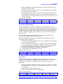
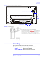
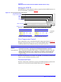
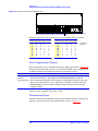
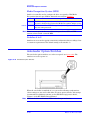
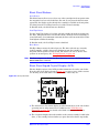
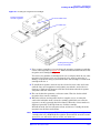
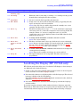
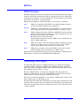
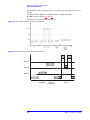
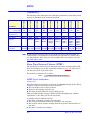
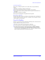
For the HP C1536A, data compression can be controlled through the jumper pin
shown in figure 2.6. The HP C1534A does not support data compression.
The pin is only monitored at power-on, and controls whether data compression is
enabled by default. Any subsequent change to the pin is ignored.
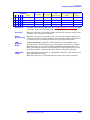
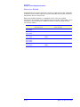
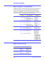
Pin State
Unconnected
(default)
Effect
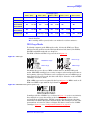
Data compression is only controlled by configuration switches 1 and 2 (on the
underside of the drive) and through MODE SELECT.
Connected to 0V Data compression is disabled. The setting of configuration switch 1 is ignored.
Switch 2 is valid. Data compression can still be controlled through MODE
SELECT . Note that when reading, the drive will decompress compressed data.
It follows, that if you are using this pin, you should set configuration switch 1 on
the underside of the drive to ON.
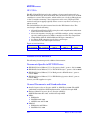
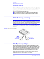
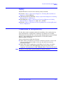
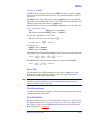
Termination Power
The HP C1534A and HP C1536A are permanently configured to provide
termination power.
SCSI Connection and Termination (DDS-2
and DSS-3 drives only)
Only a single-ended, narrow SCSI configuration is supported, with a maximum
sustained transfer rate of 8 MB/s. See Section 4, Physical Characteristics, of the
SCSI X3T9/89-042 Standard. Only use unshielded connectors.
The drive does not support termination on the device itself. Normally, drives such
as this are not required to be at the end of a bus, but if this is unavoidable, HP
recommends the use of the feed-through SCSI terminator listed below, which
plugs directly into the rear of the drive. Use active termination because the drive
is capable of a transfer rate greater than 5 MB/s.
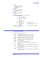
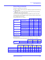
The following are possible cable and terminator sources:
Cable: 28AWG Ribbon, Spectra Strip
Connector: 3M Connector
3M Strain Relief
132-2899-887 style 2697
3425-7650
3448-3050
Terminator: Methode Active SCSI Terminator
DM550-06-R
Amphenol Active SCSI Terminator 33770
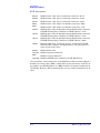
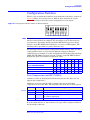
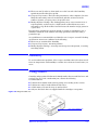
Note When using feed-through termination, termination power must be supplied to
pin 26 of the SCSI Interface. Power can be supplied by any device on the bus. If
you want the drive to supply it, set a jumper across the two pins marked “Term
power” in figure 2.7.
Be careful when inserting and removing feed-through terminators, to avoid
damaging the end walls of the terminator and the drive.
Edition 8—December 1999
2-5