1
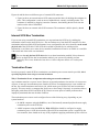
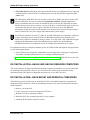
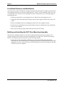
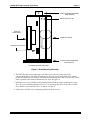
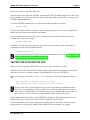
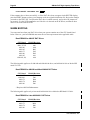
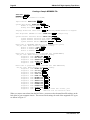
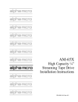
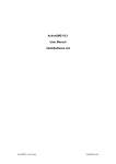
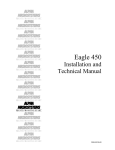
AM-647, 648 & 649
Digital Audio Tape (DAT)
High Capacity Tape Drives
Installation Instructions
PDI-00649-00, A01
FIRST EDITION: August 1997
To re-order this document, request part number PDI-00649-00
FCC Notice
This equipment has been tested and found to comply with the limits for a Class A digital device, pursuant to Part 15 of the FCC
Rules. These limits are designed to provide reasonable protection against harmful interference when the equipment is operated in a
commercial environment. This equipment generates, uses and can radiate radio frequency energy and, if not installed and used in
accordance with the instruction manual, may cause harmful interference to radio communications. Operation of this equipment in a
residential area is likely to cause harmful interference in which case the user will be required to correct the interference at his own
expense.
Canadian Department of Communications Compliance Statement
This equipment does not exceed Class A limits per radio noise emissions for digital apparatus set out in the Radio Interference
Regulations of the Canadian Department of Communications. Operation in a residential area may cause unacceptable interference
to radio and TV reception requiring the owner or operator to take whatever steps are necessary to correct the interference.
Avis de Conformité aux Normes du Ministère des Communications du Canada
Cet équipment ne deapsse pas les limits de Classe A d'émission de bruits radioélectriques pour les appareils numeriques tels que
prescrites par le Règlement sur le brouillage radioélectrique établi par le ministère des Communications du Canada. L'exploitation
faite en milleu résidential peut entrainer le brouillage des réceptions radio et tele, ce qui obligerait le propriétaire ou l'opératour à
pendre les dispositions nécessaires pour en éliminer les causes.
Battery Warning
CAUTION: Danger of explosion if battery is incorrectly replaced. Replace only with the same or equivalent type recommended by the
manufacturer. Discard used batteries according to the manufacturer's instructions.
ATTENTION: Il y a danger d'explosion s'il y a replacement incorrect de la batterie. Remplacer uniquement avec une batterie du
même type ou d'un type recommandé par le constructeur. Mettre au rébut les batteries usagées conformément aux instructions du
fabricant.
For AM-6000 systems, replace batteries with Panasonic or Ray-O-Vac BR1225 only. Use of another battery may present a risk of fire
or explosion. Replacement batteries may be ordered from your authorized Alpha Micro reseller.
Electrical Warning
This equipment contains components that can be damaged by static electricity. Follow all electronic discharge precautions when
handling the equipment. For example, touch the metal back panel of the CPU or peripheral chassis to dissipate any electrical charge
before touching the circuit boards or equipment within the chassis. After turning off power, before you open your computer chassis,
unplug the cord from the electrical outlet to guard against electrical shock.
SOFTWARE SECURITY DEVICE IDENTIFICATION NUMBER: _________________
The Alpha Micro Software Security Device (SSD) is a customized integrated circuit that personalizes the computer, providing identity
verification for it. Certain Alpha Micro and non-Alpha Micro software may require that your computer contain an SSD in order to run
software that has been customized to run only on your computer.
Please enter the identification of your SSD above. The SSD identification number should be on your computer ID label under "SSD
Serial No." (Another way of finding the number is to look at the SSD itself. The SSD is located in an integrated circuit location on the
CPU board; its identification number is printed on the SSD itself.) Software vendors may ask you for the SSD number if they are
customizing software to run only on your computer.
This document may contain references to products covered under the following U.S. Patent Number(s): 4,530,048
ALPHA MICROSYSTEMS
2722 Fairview Street
P. O. Box 25059
Santa Ana, CA 92704
Table of Contents
INTRODUCTION
PRODUCT DESCRIPTIONS
Common Characteristics
SCSI Bus Terminology
AM-647 (Archive) DAT Drive Characteristics
AM-648 (Exabyte) DAT Drive Characteristics
AM-649 (HP) DAT Drive Characteristics
Drive Mounting Kits
TOOLS REQUIRED
PREPARING THE DAT DRIVE FOR INSTALLATION
Jumpers and Switch Settings
SCSI BUS TERMINATION
Termination Resistor Pack Locations
External SCSI Bus Termination
Internal SCSI Bus Termination
Termination Power
DAT INSTALLATION—EAGLE AND AM-1600 DESKSIDE COMPUTERS
DAT INSTALLATION—RACK MOUNT AND PEDESTAL COMPUTERS
Front Bezel Removal and Modification
Building and Installing the DAT Drive Mounting Assembly
Power and Interface Cables
DAT INSTALLATION—AM-1400 AND AM-1600 DESKTOP COMPUTERS
DAT INSTALLATION—AM-990 COMPUTERS
SOFTWARE INFORMATION FOR DAT DRIVES
OPERATING SOFTWARE—MINIMUM FILE VERSIONS
COPYING THE GENERIC DEVICE DRIVER
MODIFYING THE SYSTEM INITIALIZATION COMMAND FILE
TESTING THE INITIALIZATION FILE
WARM BOOTING
RUNNING SELF TEST
AM-647 DAT DRIVE STATUS LEDS
AM-648 DAT DRIVE STATUS LEDS
AM-649 DAT DRIVE STATUS LEDS
USING YOUR DAT DRIVE
MAINTENANCE
TAPE FORMATS, USAGE, AND CAPACITIES
DDS, DDS-1, DDS-2, and Media Recognition
DAT Tape Identification
Tape Capacities
ADDITIONAL DOCUMENTATION
PDI-00649-00, A01
1
1
1
1
2
2
2
2
3
3
3
9
9
10
12
12
13
13
14
14
18
19
21
22
23
24
24
25
26
29
29
30
31
32
35
35
36
36
37
37
Page ii
AM-64x DAT High Capacity Tape Drives
List of Figures
Figure 1 - AM-647 Configuration—3.5” Wide Model
Figure 2 - AM-647 Configuration—5.25” Wide Model
Figure 3 - AM-648 (Exabyte) Configuration
Figure 4 - AM-649-00 Configuration—HP Model C1536A
Figure 5 - AM-649-01 Configuration—HP Model C1533A/C1599A
Figure 6 - AM-649-00 and -01 Configuration Option Switches
Figure 7 - AM-648 (Exabyte) On-Board Terminators
Figure 8a - External SCSI Terminator - Narrow
Figure 8b - External SCSI Terminator - Wide
Figure 9 - Drive Mounting Assembly
Figure 10 - Plastic Mounting Base
Figure 11 - Metal Top Support Bracket
Figure 12 - Securing the Drive Assembly to the Front Bezel
Figure 13 - AM-1400/1600 Drive Mounting Bracket
Figure 14 - AM-1400/1600 Drive Mounting Assembly
Figure 15 - Peripheral Mounting Rail
Figure 16 - Attaching Mounting Rails to Peripheral
Figure 17 - DAT Warm Boot—CPU Boot Switch Settings
Figure 18 - AM-647 DAT Drive Faceplate
Figure 19 - AM-648 DAT Drive Faceplate
Figure 20 - AM-649 DAT Drive Faceplate
Figure 21 - Loading a DAT Tape Cartridge
Figure 22 - DAT Tape Cartridge Logos
4
5
6
7
8
9
10
11
11
15
16
17
18
19
20
21
22
29
30
31
31
33
36
PDI-00649-00, A01
AM-64x DAT High Capacity Tape Drives
Page 1
INTRODUCTION
This document describes the installation of the AM-647, AM-648, and AM-649 Digital Audio Tape
(DAT) SCSI High Capacity Tape Drives into an Alpha Micro computer system.
If you are installing a DAT drive into an external subsystem, use the installation instructions
shipped with the subsystem. If you are installing a DAT drive in a Series 90 computer,
installation instructions are included in the Series 90 SCSI tape drive controller documentation.
These instructions are written for an experienced Alpha Micro Service Technician. If you do not feel
comfortable performing the hardware and software procedures discussed below, contact your Alpha
Micro VAR or the Alpha Micro Technical Assistance Center for help.
PRODUCT DESCRIPTIONS
This manual covers several different DAT tape drives for use in various Alpha Micro computers. Cable
connections, software installation, and use are essentially the same for all DAT drives. However, each
DAT has certain unique operational characteristics.
Common Characteristics
• Can be mounted in any 5.25” configuration
• Must be attached to the system SCSI bus
• Use 4mm magnetic tape
• Use the same 647DVR.DVR software driver
SCSI Bus Terminology
Over the years, Alpha Micro computers have offered three different “SCSI” busses. We refer to them as
follows:
1. The bus in AM-2000/3000 and other older computers, which supports up to four SCSI devices,
is the “SASI bus.”
2. The SCSI bus in Eagles, Roadrunners, the AM-4000, and newer computers, which requires a
SCSI dispatcher and supports up to seven devices, is the “SCSI-2 bus.”
3. The enhanced Wide SCSI-2 bus introduced on the AM-6000 and Roadrunner 060 is the “Wide
SCSI-2 bus.” This bus supports up to 15 devices.
PDI-00649-00, A01
Page 2
AM-64x DAT High Capacity Tape Drives
AM-647 (Archive) DAT Drive Characteristics
• Two models: a 3.5” half-height drive, and a 5.25” half-height drive.
• Both drives have the same operational characteristics.
• Has a data capacity of approximately 2 gigabytes using 90 meter tapes
• Can be used on a SASI or SCSI-2 bus, including Wide SCSI-2 with an appropriate adapter
• CANNOT read/write compressed data tapes
AM-648 (Exabyte) DAT Drive Characteristics
• Has a data capacity of approximately 2 gigabytes in standard DDS (non-compressed) mode, and
approximately 4 gigabytes in DDS-DC compressed mode with a 90 meter tape
• Can be used on a SCSI-2 bus only, including Wide SCSI-2 with an appropriate adapter
• Can be forced into compressed or non-compressed mode using the AMOS TMODE command
AM-649 (HP) DAT Drive Characteristics
• There are two models of the AM-649 DAT drive:
• The AM-649-00 4 gigabyte drive (HP model C1536A) has a data capacity of
approximately 2 gigabytes in DDS (non-compressed) mode, and approximately 4
gigabytes in DDS-DC compressed mode with a 90 meter tape.
• The AM-649-01 8-gigabyte drive (HP model C1533A or C1599A) has the same data
capacities as the AM-649-00 using DDS/DDS-1 tape, with additional DDS-2 capabilities
yielding approximately 4 gigabytes of storage in native DDS-2 mode and 8-gigabytes in
DDS-2-DC compressed mode, when used with 120 meter DDS-2 tapes. In DDS-2 mode,
file access and data transfer rates are significantly faster than DDS/DDS-1 modes.
• Can be used on a SCSI-2 bus only, including Wide SCSI-2 with an appropriate adapter
• Can be forced into compressed or non-compressed mode using the AMOS TMODE command
See the "DAT Drive Compatibility" section of this manual and the TMODE reference sheet in
the Alpha Micro System Commands Reference Manual for more details on switching between
compressed and non-compressed data modes.
Drive Mounting Kits
In addition to the DAT tape drive, some installations require a drive mounting kit. Each mounting kit
includes the hardware to install a DAT drive in a particular type of computer. The following chart shows
the mounting kits needed for different Alpha Micro computers:
PDI-00649-00, A01
AM-64x DAT High Capacity Tape Drives
System Type
VME Rack Mount
VME Pedestal
AM-2000M/AM-3000M *
AM-1400/AM-1600 Desktop **
AM-990 VME and SBC
Eagle Deskside
AM-1600 Deskside
Page 3
Mounting Kit
PDB-00625-60
PDB-00625-61
PDB-00625-61
PDB-00647-50
Not required
Not required
Not required
* With Roadrunner or AM-540 upgrade (AM-649-01 not compatible with AM-540)
** For AM-647 DAT drives only—other models not compatible
Make sure you have the correct mounting kit before you begin. The DAT drive has the same
environmental specifications as your computer.
TOOLS REQUIRED
For most installations, the only tools you need to install the DAT drive are a #2 Phillips-head
screwdriver and a pair of needle-nose pliers.
PREPARING THE DAT DRIVE FOR INSTALLATION
First, you need to select the SCSI ID of the DAT drive by setting the proper switches on the back of the
drive. If your computer uses a SCSI bus, you have seven SCSI IDs to choose from (0 through 6). The
SASI bus supports only SCSI IDs 0 through 3. Don't worry if you have a gap in your device addressing;
AMOS doesn't require that each device be defined in sequence.
Except for systems with a CMOS configuration menu, such as the Eagle 550 and Roadrunner
060, if you want to be able to warm boot from your DAT drive, you must set it to a higher SCSI
ID than any other tape device on the bus.
While the Wide SCSI-2 bus supports IDs up to 15, all Alpha Micro DAT drives are narrow SCSI
devices. You cannot set one to an ID higher than 6, even if it is attached to the Wide SCSI-2 bus
with an adapter.
Jumpers and Switch Settings
Refer to the following illustrations for configuration and jumper locations for your DAT drive.
There are two physically different types of AM-647 DAT drives: a 3.5” wide, half-height drive in
a 5.25” mounting bracket, and a full 5.25” wide, half-height drive. Although their physical sizes
and the locations of jumpers and switches are different, the same configuration rules apply to
both.
PDI-00649-00, A01
Page 4
AM-64x DAT High Capacity Tape Drives
DAT DRIVE
MOUNTING HOLES
NO JUMPERS INSTALLED AT THIS LOCATION
1
RD2
SW1
JP4
RD1
TERMINATORS
SW1
SCSI ID
O
F
F
0
1
2
3
4
5
6
7
8
JP4 "IN" = DRIVE SUPPLIES TERMINATION
POWER TO THE SCSI BUS.
O
F
F
O
F
F
JP4 "OUT" = DRIVE DOES NOT SUPPLY
TERMINATION POWER TO THE
SCSI BUS.
1
1
2
3
1
2
3
O
F
F
O
F
F
2
O
F
F
O
F
F
3
6
1
2
3
1
2
3
Leave switches 6, 7, and 8
set as shown in the illustration.
5
1
2
3
1
2
3
PARITY IS ENABLED AND DISABLED USING
SWITCH #5. FOR AMOS BASED COMPUTERS,
SWITCH #5 WLL ALWAYS BE SET TO THE "OFF"
OR DISABLED POSITION. SERIES 90 PRODUCTS
WILL SET SWITCH #5 TO THE "ON" OR ENABLED
POSITION.
4
SWIITCH #4 IN THE "OFF" POSITION = SCSI-1
SWITCH #4 IN THE "ON" POSITION = SCSI-2
Figure 1 - AM-647 Configuration—3.5” Wide Model
PDI-00649-00, A01
AM-64x DAT High Capacity Tape Drives
Page 5
O
F
F
1
2
3
4
5
6
7
8
TERMINATION POWER JUMPER
0UT = TERMINATION POWER DISABLED
IN = TERMINATION POWER ENABLED
TERMINATORS
PIN-1
SW1
SCSI ID
O
F
F
0
1
2
3
4
5
6
7
8
O
F
F
O
F
F
1
1
2
3
1
2
3
O
F
F
O
F
F
2
O
F
F
O
F
F
3
SWIITCH #4 IN THE "OFF" POSITION = SCSI-1
SWITCH #4 IN THE "ON" POSITION = SCSI-2
Figure 2 - AM-647 Configuration—5.25” Wide Model
PDI-00649-00, A01
6
1
2
3
1
2
3
Leave switches 6, 7, and 8
set as shown in the illustration.
5
1
2
3
1
2
3
PARITY IS ENABLED AND DISABLED USING
SWITCH #5. FOR AMOS BASED COMPUTERS,
SWITCH #5 WLL ALWAYS BE SET TO THE "OFF"
OR DISABLED POSITION. SERIES 90 PRODUCTS
WILL SET SWITCH #5 TO THE "ON" OR ENABLED
POSITION.
4
Page 6
AM-64x DAT High Capacity Tape Drives
PIN-1
KEYED
CONNECTOR
DC POWER
SCSI ID #0
SCSI ID #1
SCSI ID #4
SCSI ID #2
SCSI ID #5
SCSI ID #3
SCSI ID #6
The two outside pins (shown in gray) are used to
select SCSI-1 or SCSI-2. With the jumper removed,
the drive is configured for SCSI-2; with the jumper
installed the drive is configured for SCSI-1. For all
Alpha Micro configurations, the drive must be
configured for SCSI-2 operation.
Figure 3 - AM-648 (Exabyte) Configuration
PDI-00649-00, A01
AM-64x DAT High Capacity Tape Drives
Page 7
The AM-649-00 4 gigabyte DAT drive (HP model C1536A) has no provision to disable its term
power! Therefore, this drive should only be installed in the main system chassis and connected
to the same power supply as the rest of the internal SCSI peripheral devices. This drive should
never be connected to a different/subsystem power supply, as erratic system operation may
result!
HP 4mm DAT Drive - Model C1536A (4 GB)
SCSI
2 1 0 NC
SCSI ADDRESS JUMPERS
MC1277
2 1 0 NC
SCSI I.D. 0
2 1 0 NC
SCSI I.D. 4
PIN-1
SCSI CONNECTOR
2 1 0 NC
SCSI I.D. 1
2 1 0 NC
SCSI I.D. 2
2 1 0 NC
SCSI I.D. 5
DC POWER
2 1 0 NC
SCSI I.D. 3
2 1 0 NC
SCSI I.D. 6
Figure 4 - AM-649-00 Configuration—HP Model C1536A
PDI-00649-00, A01
Page 8
AM-64x DAT High Capacity Tape Drives
The AM-649-01 may be labeled as either Model C1533A or C1599A. From an AMOS standpoint,
these models are identical. AMOS software which returns the model number displays C1533A for
either drive.
When configuring the AM-649-01 drive, be sure to remove the TERM POWER jumper located next to
the SCSI ID jumpers.
NC
SCSI 0
SCSI 1
SCSI 2
TERM
PWR
HP 4mm DAT Drive - Model C1533A/C1599A (8 GB)
SCSI ADDRESS JUMPERS
SCSI I.D. 4
NC
SCSI 0
SCSI 1
NC
SCSI 0
SCSI 1
SCSI 2
SCSI I.D. 3
TERM
PWR
NC
SCSI 0
SCSI I.D. 5
SCSI 2
TERM
PWR
NC
SCSI 1
SCSI 2
TERM
PWR
NC
SCSI 0
SCSI 1
DC POWER
SCSI I.D. 2
SCSI 1
SCSI 2
TERM
PWR
SCSI I.D. 1
NC
SCSI 0
SCSI 1
SCSI 2
SCSI 2
TERM
PWR
NC
SCSI 0
SCSI 1
SCSI 2
TERM
PWR
TERM
PWR
SCSI I.D. 0
SCSI 0
PIN-1
SCSI CONNECTOR
SCSI I.D. 6
Figure 5 - AM-649-01 Configuration—HP Model C1533A/C1599A
The AM-649-00 and -01 each have a series of eight option switches located on the bottom of the drive.
These switches control compression modes, the Media Recognition System, and compatibility issues
with other computer manufacturers. Refer to Figure 6 for settings and details.
PDI-00649-00, A01
AM-64x DAT High Capacity Tape Drives
Page 9
HP 4mm DAT Option Switches
ON
1
2
3
4
5
6
7
8
AMOS Default Configuration
SWITCH 1
SWITCH 2
MEANING
--------------------------------------------------------------------------------------------------------------On
On
Off
On
Off
On
Off
Off
Compression enabled at power-on, with host control
Compression enabled at power-on, no host control
Compression disabled at power-on, the host is allowed to
control compression
Compression disabled at power-on, no host control
SWITCH 3
MEANING
--------------------------------------------------------------------------------------------------------------On
The Media Recognition System is disabled. All DDS tapes will be treated
the same, whether they possess the Media Recognition Stripes or not.
The Media Recognition System is active. This is the default. Non-Media
Recognition System tapes are treated as if they are write-protected.
Off
SWITCHES 4 - 8
--------------------------------------------------------------------------------------------------------------Switches 4-8 are used to specify drive connectivity and functionality according to host or
customer requirements. The majority of functions controlled by these switches concern
UNIX software and operational compatibility with SUN, IBM, and DEC computer systems.
The AMOS default setting is switches 4-8 set to on.
Figure 6 - AM-649-00 and -01 Configuration Option Switches
SCSI BUS TERMINATION
To function properly, the SCSI bus on your computer must be terminated at each end of the cable. The
SCSI controller terminates one end of the bus; the opposite end of the bus can be terminated in one of
two ways: 1) using the preferred method—an external terminator, or 2) installing on-board terminators in
the peripheral that's at the other end of the SCSI cable. You should use method 2 only if, for some
reason, you cannot use an external terminator in your installation.
Termination Resistor Pack Locations
Under most conditions, if the new peripheral device has on-board terminators they should be removed!
The terminators should be left installed only if you are not using an external terminator, and the drive
you're installing is physically connected as the last device on the SCSI cable.
AM-649-00 and -01 drives (HP models C1536A, C1533A, and C1599A) DO NOT HAVE ONBOARD TERMINATORS. If these drives are used without an external terminator, they cannot
be the last device on the SCSI cable. Another device must be attached as the last device on the
SCSI cable and configured to provide SCSI bus termination!
PDI-00649-00, A01
Page 10
AM-64x DAT High Capacity Tape Drives
Figures 1 and 2 show the location of the AM-647 on-board terminators. Refer to Figure 7 for the location
of the AM-648 on-board terminators.
AM-648 ON-BOARD TERMINATORS
Figure 7 - AM-648 (Exabyte) On-Board Terminators
External SCSI Bus Termination
The preferred way to terminate the SCSI bus in an AMOS computer is to install an external terminator.
In April of 1993, the external SCSI bus terminator became standard on all AMOS computers. Using an
external terminator makes it easier to install an add-on subsystem (like a portable CD-ROM drive),
eliminating the need to remove terminators from a SCSI device inside the computer.
As computer performance increases, the SCSI bus becomes more sensitive to termination issues. Newer
AMOS computers, such as the AM-6000, require active termination of the SCSI bus. Check your
computer Owner’s Manual to make sure you are terminating the SCSI bus properly.
External terminators are available from Alpha Micro under part numbers PRA-00222-00 (narrow passive
terminator), PRA-00222-21 (narrow active terminator), and PRA-00222-20 (wide active terminator).
To use the external terminator, you need to insure none of the SCSI devices inside the computer are
terminated. You also need to follow the guidelines in the section on providing termination power to the
SCSI bus.
PDI-00649-00, A01
AM-64x DAT High Capacity Tape Drives
Page 11
10- and 21-slot rack mount VME computers have no external SCSI connector. To install an external
terminator, you need a special adapter cable, DWB-10200-01. The connector on this cable is compatible
with the external terminator and also allows you to easily attach a portable CD-ROM drive or other SCSI
device.
The figures below show both narrow and wide SCSI terminators:
BAIL LOCKS
I
S
SC
Figure 8a - External SCSI Terminator - Narrow
PRA-00222-20
EXTERNAL SCSI BUS
TERMINATOR
SCSI CONNECTOR
ON BACK PANEL
Figure 8b - External SCSI Terminator - Wide
PDI-00649-00, A01
Page 12
AM-64x DAT High Capacity Tape Drives
Figures 8a and 8b show two different types of external SCSI connectors:
1. Figure 8a shows an external narrow SCSI connector and bail locks for holding the terminator in
place. This configuration is used on most of Alpha Micro's currently available product. The
terminator is installed by plugging it onto the connector, then latching the bail locks into the
notches on the sides of terminator.
2. Figure 8b shows an external wide SCSI connector. The terminator is held in place by thumb
screws.
Internal SCSI Bus Termination
If you are not using external SCSI termination, you may terminate the SCSI bus by enabling the
termination resistors on the last SCSI device—the one farthest away from the SCSI controller. For best
termination and most reliable SCSI performance in any configuration, this device should be at the actual
physical end of the SCSI cable. If the SCSI cable extends beyond the device which provides
termination, even if there are no more devices attached, termination will not be as reliable as it would be
if the actual end of the cable was terminated.
Be sure that only the last SCSI device has its on-board termination enabled. If more than one
device on the SCSI bus has its termination enabled, your system will probably perform
erratically! This is true whether the last device is in the computer chassis or in a subsystem
chassis.
Termination Power
In order to properly control SCSI bus termination, a termination power source must be provided; this is
especially important when using an external terminator.
Why is Termination Power so important when using an external terminator?
Any terminator must have a power source. Because an external terminator does not have its own source
of power, it must get its termination power from the SCSI bus. If termination power is not available on
the bus, the external terminator cannot do its job, which means your SCSI bus will not be terminated
properly. This may result in a computer that won't boot, or that "hangs" frequently. As mentioned above,
the higher performance SCSI-2 and Wide SCSI-2 busses are more prone to exhibit problems when
improperly terminated than was the older SASI bus.
The termination power source can be configured in one of the following ways, depending on your
system hardware:
• In AMOS computers using the SASI bus, one of the internally mounted peripherals must supply
termination power to the SCSI bus.
• AMOS computers using the SCSI-2 or Wide SCSI-2 bus should be configured to supply
termination power via the host controller. When SCSI bus termination power is supplied by the
host controller, there should not be any SCSI peripherals supplying termination power to the bus.
PDI-00649-00, A01
AM-64x DAT High Capacity Tape Drives
Page 13
• SCSI subsystems attached to the main system should not have any additional devices supplying
termination power to the SCSI bus. Termination power for the bus should be supplied by one
source only!
The AM-649-01 (8GB) DAT drive has a jumper on the rear to disable term power, but the AM649-00 (4GB) DAT drive has its term power permanently enabled! Although Alpha Micro
always recommends only one source of termination power to the bus, this particular exception
has thus far proven not to be a problem—as long as the drive is installed in the main system and
connected to the same DC power supply as the other SCSI devices on the bus. However,
performance of this drive may become unstable if it's mounted in an external subsystem chassis
and/or connected to a DC power supply other than the main system supply!
The SCSI host controllers on AM-137, AM-190, and AM-540 boards are permanently configured
to supply termination power to the SCSI bus. On Roadrunner boards, the termination power
feature can be enabled or disabled by setting a jumper. As of July 26th, 1994, Alpha Micro began
configuring all Roadrunner boards with termination power enabled. See the Roadrunner
installation instructions for information on how to configure the termination power jumper.
For information on how to configure terminator power on SCSI hard disk and magnetic tape peripherals,
see the following documents:
• Each SCSI disk drive shipped by Alpha Micro has a one page notice with jumper configuration
information, including instructions on how to configure termination power.
• AM-62X SCSI 1/4" Streaming Tape Drive Installation Instructions, PDI-00625-00, revision A07
or later.
DAT INSTALLATION—EAGLE AND AM-1600 DESKSIDE COMPUTERS
The owner's manuals for Eagle and AM-1600 deskside computers contain their own sets of instructions
for installing SCSI peripherals. However, you will still need to follow all the instructions in this
document dealing with software configuration and actual use of your DAT tape drive.
DAT INSTALLATION—RACK MOUNT AND PEDESTAL COMPUTERS
The following sections describe how to install the DAT drive into AMOS computers using both rack
mount and pedestal enclosures. The basic installation procedure is the same for both pedestal and rack
mount computers:
• Remove your front bezel.
• Create a cutout in your bezel to support the DAT drive.
• Build the DAT drive mounting assembly.
• Install the DAT drive mounting assembly in your computer.
• Attach the SCSI interface and power cables.
PDI-00649-00, A01
Page 14
AM-64x DAT High Capacity Tape Drives
Front Bezel Removal and Modification
Your DAT drive product installation kit includes instructions describing how to modify your front bezel.
The modification requires you to make a half-height 5.25” cutout if you are installing a DAT drive only,
or a full-height 5.25” cutout if you are installing a DAT drive along with a new (or existing) floppy or
streaming tape drive.
1. Follow the instructions in your computer Owner's Manual for removing the top cover.
2. Unplug the ribbon cable that links the display panel on the computer's front bezel to your CPU
board.
3. Remove the Phillips-head screws holding the front bezel to the computer's chassis.
4. Follow the bezel modification instructions included with your installation kit, then reinstall the
bezel on your computer.
5. Don't forget to plug the display panel cable back into your CPU board.
Building and Installing the DAT Drive Mounting Assembly
The DAT drive mounting assembly is the same for both pedestal and rack mount computers. The
assembly consists of three pieces; one plastic mounting base, one DAT drive, and one metal support
bracket. The following steps describe how to put the assembly together:
1. Set the drive on top of the plastic mounting base with its status LEDs nearest the plastic
mounting base. This insures the drive is in the proper position for both pedestal and rack mount
computers. Also, pin-1 on the DAT drive's SCSI connector has the same orientation as the other
SCSI devices in your computer.
PDI-00649-00, A01
AM-64x DAT High Capacity Tape Drives
Page 15
METAL SUPPORT BRACKET
DWF-20260-00
DRIVE ACTIVITY LED
SCSI DAT
TAPE DRIVE *
DISKETTE DRIVE
DRIVE ACTIVITY LEDs
PLASTIC MOUNTING BASE
DWF-20218-00
* Faceplate varies per DAT model.
Figure 9 - Drive Mounting Assembly
2. The DAT drive has several mounting screw-holes on its side rails, which align with
corresponding holes in the plastic mounting base. Align the screw holes on the drive with the
proper holes (marked as A in Figure 10) in the plastic mounting base. Make sure the drive's front
panel is pointed in the direction indicated by the arrow in Figure 10.
3. Install the two screws (included in the mounting kit) that hold the plastic mounting base to the
drive. If you are installing a diskette drive or a 1/4" streaming tape drive along with your DAT
drive, mount it next to the DAT drive, as shown in Figure 9.
4. Set the drive assembly into its mounting position inside the chassis.
PDI-00649-00, A01
Page 16
AM-64x DAT High Capacity Tape Drives
DWF-20218-00
W
E O
TH RR
S IN E A
'
E
IV ED TH
DR INT BY
O
D
E
TH IS P ATE
E
C
L
I
R E D
SU N IN
E T PA N
K
IO
MARON CT
F IRE
D
A
B
A
SCSI DAT OR STREAMING TAPE DRIVE, or
ANY 5-1/4" HALF-HEIGHT SCSI HARD DISK DRIVE
B
AM-645 FULL-HEIGHT 8MM MAGNETIC TAPE DRIVE, or
ANY 5-1/4" FULL-HEIGHT SCSI HARD DISK DRIVE
C
ANY 5-1/4" HALF-HEIGHT FLOPPY DISKETTE DRIVE, or
ANY 5-1/4" HALF-HEIGHT SCSI HARD DISK DRIVE
C
Figure 10 - Plastic Mounting Base
6. Set the metal support bracket on top of the drive assembly as shown in Figure 9. Position the
bracket so the mounting hole (see Figure 11) aligns with the screw hole on the side (top) of the
DAT drive and the screw hole in the metal support bracket aligns with the screw hole in the
front bezel.
PDI-00649-00, A01
AM-64x DAT High Capacity Tape Drives
S
W
E'
O
IV
R HE RR
D T A
TE IN HE
ET ED T
K
Y
IS T B
D OIN D
E P TE
TH IS A
E EL DIC
R N N
SU PA N I
E
T IO
AK N T
M RO EC
F IR
D
Page 17
DWF-20260-00
MOUNTING BRACKET
DAT TAPE DRIVE
MOUNTING HOLE
DISKETTE DRIVE
MOUNTING HOLES
Figure 11 - Metal Top Support Bracket
7. Before you tighten the screw holding the DAT drive to the metal support bracket, make sure you
are satisfied with the way the drive assembly is aligned with the cutout in your computer's front
bezel. Once the drive (or drives) are properly positioned, install the screw that holds the plastic
mounting base to the chassis bottom and tighten the screw holding the drive (or drives) to the
metal support bracket. Finally, tighten the screw that secures the drive assembly to the front
bezel, as shown in Figure 12.
PDI-00649-00, A01
Page 18
AM-64x DAT High Capacity Tape Drives
FRONT BEZEL
NYLON SHOULDER WASHERS
(HDW-10004-07)
METAL SUPPORT BRACKET
DWF-20260-00
DAT TAPE DRIVE
Figure 12 - Securing the Drive Assembly to the Front Bezel
Power and Interface Cables
The 50-pin SCSI cable is already installed in your computer. On some computers, the 50-pin SCSI
interface cable has keyed connectors that insure a pin-1 to pin-1 connection with the DAT drive. If your
interface cable is not keyed, be sure to use the colored stripe on the cable as a pin-1 reference.
If your computer uses the 68-pin Wide SCSI-2 bus, you must use the appropriate 50-pin to 68-pin
adapter to connect the DAT drive to the SCSI cable.
Plug the 4-pin keyed power cable into the corresponding keyed connector on the back of the DAT drive.
PDI-00649-00, A01
AM-64x DAT High Capacity Tape Drives
Page 19
DAT INSTALLATION—AM-1400 AND AM-1600 DESKTOP
COMPUTERS
1. Remove the four Phillips head screws (two on each side) that hold the top cover in place.
Remove the top cover and place it in an area where it won't get damaged.
2. Remove the four screws that hold the drive mounting bracket in place. The bracket is shown in
Figure 13—the screws are at positions A, B, C, and D. Remove the mounting bracket from the
chassis.
B
DRIVE MOUNTING BRACKET
A
D
C
Figure 13 - AM-1400/1600 Drive Mounting Bracket
3. The DAT drive installs on top of the drive mounting bracket. However, because the DAT drive
internally ties logic ground to its frame, you need to isolate the DAT drive from the computer
chassis. The mounting kit includes an isolator designed to prevent the drive from making metal
to metal contact with the computer chassis.
Fold and position the ground isolator (part number DWF-20713-00) as shown in Figure 14, with
the part number facing up and forward. The isolator has been scored so the edges can be folded
up as shown.
4. Once the isolator is folded and positioned, place the drive on top of the isolator and attach it
with four plastic hex screws and metal washers.
PDI-00649-00, A01
Page 20
AM-64x DAT High Capacity Tape Drives
AM-648 DAT TAPE
DRIVE
AC/DC GROUND
ISOLATOR
DRIVE MOUNTING
BRACKET
13-00
DWF-207
PLASTIC
HEX SCREW
METAL
WASHER
Figure 14 - AM-1400/1600 Drive Mounting Assembly
5. After the drive is installed on the mounting bracket, place the assembly back into the chassis and
re-attach the four screws that hold the mounting bracket in place.
6. There is a SCSI interface cable with two 50-pin connectors already installed in the chassis.
Simply plug the 50-pin connector into the back of the DAT drive. Make sure the colored stripe
on the cable aligns with pin-1 on the drive. Refer to the Figures 1 and 2 for the pin-1 location.
7. Your system should also have one or two standard 4-pin power connectors available. Plug one
of these power connectors into the drive. The connectors are keyed, so you can't plug them in
backwards without excessive force.
8. When the drive installation is complete, reinstall the top cover.
PDI-00649-00, A01
AM-64x DAT High Capacity Tape Drives
Page 21
DAT INSTALLATION—AM-990 COMPUTERS
The DAT drive is installed in the AM-990's main drive bay using plastic mounting rails. You need two
rails to mount the drive. The rails (DWF-20652-00) are universal; they can be mounted on either the
right or left side of the drive.
Figure 15 shows one of the mounting rails and explains how they are used with various types of
peripherals, including the DAT tape drive:
PERIPHERAL MOUNTING RAIL
DWF-20652-00
SHORT
END
LONG
END
Use the top holes for
mounting full-height devices
Use the bottom holes for
mounting half-height devices
SHORT END
For Tandberg 1/4" streaming tape drives and all hard disk drives, mount
the rails with the short end pointing toward the rear of the computer
LONG END
For DAT tape drives, mount the rails with the long end pointing toward
the rear of the computer cabinet.
Figure 15 - Peripheral Mounting Rail
Besides the plastic rails, the peripheral mounting kit includes both standard and metric screws for
compatibility with all of Alpha Micro's 5.25” peripherals.
Be sure to observe the correct orientation of the long and short ends of the mounting rails. If
they're not installed correctly, the front of the drive will not align flush with the front of the
system chassis when the device is slid into place.
PDI-00649-00, A01
Page 22
AM-64x DAT High Capacity Tape Drives
DWF-20652-00
MOUNTING RAIL
Figure 16 - Attaching Mounting Rails to Peripheral
Once the rails are installed, slide the tape drive into its mounting position in the chassis. Make a pin-1 to
pin-1 connection between the SCSI connector on the back of the drive and the interface cable (if
attaching the drive to a 68-pin wide SCSI cable, be sure to use the correct adapter); plug in the power
cable and the installation is complete.
The DAT tape drive can be mounted horizontally as shown, or vertically on either side. However,
the drive should never be mounted upside-down!
SOFTWARE INFORMATION FOR DAT DRIVES
There are several points to remember when using DAT drives:
• Depending on your system configuration, it may be possible to support up to four DAT drives in
the same system. Also, a DAT drive can be used with a Tandberg streaming tape drive.
• DAT tape drives are not supported in S-100 bus computers, or in AM-1000/1200 computers
without a Roadrunner upgrade.
• AM-647 drives must be used with AMOS 1.4 or 2.2, or later.
• AM-648 and AM-649 drives must be used with AMOS 1.4C or 2.2C, or later.
• Later model AM-649-01 drives (those labeled C1599A) must be used with AMOS 1.4C, PR
6/97, or AMOS 2.3A, or later, only.
• The first DAT tape drive must be referred to as DAT0:.
• The device driver, DAT.DVR, must be loaded into system memory.
• Since AMOS scans from the highest SCSI ID to the lowest, if you want to warm boot from your
DAT drive it must be addressed to a higher SCSI ID than any other tape drive on the bus.
PDI-00649-00, A01
AM-64x DAT High Capacity Tape Drives
Page 23
This does not apply to computers, such as the Eagle 550 and the AM-6000, which use the CMOS
configuration menu rather than switch settings to set the boot device.
• DAT drives use the same tape utility programs used by Alpha Micro's 1/4" and 1/2" magnetic
tape drives: MTUSAV, MTUDIR, and MTURES. The use of these programs is documented in
the System Commands Reference Manual.
OPERATING SOFTWARE—MINIMUM FILE VERSIONS
The following file edit versions (or later) are required to support the various DAT drives. If your AMOS
operating system does not include the required versions as listed below, they may be obtained from
Alpha Micro Technical Assistance Center or via TABBS.
If you receive your DAT drive as part of a factory integrated computer, all the required files will
be included with your AMOS operating system.
AM-647 Minimum File Versions
For AMOS 1.4 Systems
647DVR.DVR
MTUSAV.LIT 3.0(121)
MTURES.LIT 3.0(124)
MTUDIR.LIT 3.0(117)
TAPSER.LIT 3.0(115)
WRMGEN.LIT 2.0(138)
FWUPD.LIT 1.0(100)
CRT620.LIT 2.0(112)
For AMOS 2.2 Systems
647DVR.DVR
MTUSAV.LIT 3.1(121)
MTURES.LIT 3.1(124)
MTUDIR.LIT 3.1(117)
TAPSER.LIT 3.0(115)
WRMGEN.LIT 2.0(140)
FWUPD.LIT 1.0(100)
CRT620.LIT 2.0(112)
AM-648 and AM-649 Minimum File Versions*
For AMOS 1.4C Systems
647DVR.DVR **
MTUSAV.LIT 3.2(129)
MTURES.LIT 3.2(133)
MTUDIR.LIT 3.2(127)
TAPSER.LIT 3.0(119)
WRMGEN.LIT 2.0(161)
CRT620.LIT 2.0(114)
TMODE.LIT 1.0(100)
For AMOS 2.2C Systems
647DVR.DVR **
MTUSAV.LIT 3.3(129)
MTURES.LIT 3.3(133)
MTUDIR.LIT 3.3(127)
TAPSER.LIT 3.0(119)
WRMGEN.LIT 2.0(161)
CRT620.LIT 2.0(114)
TMODE.LIT 1.0(100)
* Later model AM-649-01 drives (those labeled C1599A) require either AMOS 2.3A or AMOS
1.4C, PR 6/97.
** The AM-649 requires 647DVR.DVR from AMOS PR 3/96 or later. It will not work with earlier
versions. 647DVR.DVR is backward-compatible; the latest versions support AM-647, AM-648,
and AM-649 drives.
PDI-00649-00, A01
Page 24
AM-64x DAT High Capacity Tape Drives
If you use AMOS 2.2C we recommend you update MTUSAV, MTURES, MTUDIR, and
TAPSER to the latest possible versions. Though the new versions are not absolutely necessary to
use your DAT drive, they incorporate enhancements, such as improvements in the ability to span
tapes. The minimum file versions which include these enhancements are:
MTUSAV.LIT 3.3(134)
MTURES.LIT 3.3(138)
MTUDIR.LIT 3.3(129)
TAPSER.LIT 3.0(122)
TAPLOG.LIT 1.0(100) new utility
COPYING THE GENERIC DEVICE DRIVER
You need to create a three character driver name to support your DAT drive. This name will be used in
your system initialization command file to define the drive. Use the following commands to create a
driver called DAT.DVR:
LOG DVR: RETURN
COPY DAT.DVR=647DVR.DVR
RETURN
MODIFYING THE SYSTEM INITIALIZATION COMMAND FILE
To define the DAT drive to your computer, use the COPY command to make a copy of your system
initialization command file, calling it TEST.INI. Then edit that copy using AlphaVUE or another text
editor, making the modifications described below.
NEVER modify the system initialization command file directly. Always make your changes in a
copy of the file. When you have finished, use MONTST to test the new file. If the MONTST is
successful, you can then copy the test initialization file to AMOSL.INI or AMOS32.INI, as
applicable. If it fails, you can push the reset button to return to your standard initialization file.
If you modify your AMOSL.INI or AMOS32.INI file directly and make a mistake, the system
may not boot at all!
Type the following commands to create a test initialization file. The example below assumes your
computer uses a system initialization command file called AMOS32.INI. If your system boots using
AMOSL.INI, then substitute AMOSL.INI for AMOS32.INI.
LOG SYS: RETURN
COPY TEST.INI=AMOS32.INI
VUE TEST.INI RETURN
RETURN
The MTUSAV program spawns a separate job to communicate with the tape drive. So, the first thing to
do in your TEST.INI file is increase the number of jobs. To increase the number of jobs allocated by the
system, search for the line (normally one of the first commands in the INI file) which reads:
JOBS nnn
PDI-00649-00, A01
AM-64x DAT High Capacity Tape Drives
Page 25
Increase the number of jobs allocated by one.
The next thing to do is add a new DEVTBL statement. DEVTBL tells AMOS which devices to look for
on the computer. Every time you add a new device to the system, like your DAT drive, you must add a
DEVTBL statement defining it.
Locate the DEVTBL statements in your TEST.INI and add a line that looks like this:
DEVTBL /DAT0
DAT0 (zero) defines the DAT unit number, and the slash preceding the device name lets AMOS know
that the device(s) following the slash are non-sharable.
If you're installing more than one DAT drive, list the devices on the same line following the first
"slashed" device name. For example:
DEVTBL /DAT0,DAT1
And finally, since the device driver program needs to be in system memory, add the following line
somewhere before the final SYSTEM statement:
SYSTEM DAT.DVR[1,6]
For more information about working with the system initialization file, see the System Operator’s
Guide to the System Initialization Command File.
TESTING THE INITIALIZATION FILE
When you're done editing the TEST.INI file, save the file and exit from the text editor.
With the new DAT drive installed and its address jumpers and terminators set properly, log into OPR:,
make sure no one else is using the computer, and use MONTST to test the TEST.INI file.
When your computer executes the DEVTBL /DAT0 statement, it will display information similar to
this:
SCSI DAT driver (647DVR) version 4.0(136)
DAT0: AM-648 DAT found at SCSI id 3, SCSI-2 drive
It's okay if the driver version displayed on your screen is later than the example shown above.
However, if you're installing a more recent DAT drive (AM-648 or AM-649) and you have an
older version of 647DVR.DVR, the older driver may not be compatible with the newer drive. If
this is the case, the drive will not be recognized during bootup, and it will not work.
If the computer boots successfully, enter the DEVTBL command at AMOS command level to see a
display of the devices on your system; the DAT drive should be listed as DAT0.
If you're satisfied that your system is functioning normally, make the test INI file your new system
initialization file by copying it to AMOS32.INI or AMOSL.INI, as applicable. For example:
PDI-00649-00, A01
Page 26
AM-64x DAT High Capacity Tape Drives
COPY AMOS32.INI=TEST.INI
RETURN
If the computer doesn't boot successfully, or if the DAT drive does not appear in the DEVTBL display,
press the RESET button to reboot your computer under its original initialization file. Review the changes
you made to the TEST.INI. Verify that the DAT drive is cabled correctly, and its drive ID jumpers are
set properly. Use the SCSI command to see if the drive is detected on the SCSI bus, and that no other
device is set to the same SCSI ID
WARM BOOTING
You can warm boot from your DAT drive when your system contains one of the CPU boards listed
below. However, your boot PROMs must meet the revision requirements in the applicable table:
Boot PROMS for AM-647 DAT Drives
CPU Board
AM-134-XX
AM-135-XX
AM-140
AM-145
AM-175
AM-180
AM-185
AM-185(-50)
PROM Revision
A00
A00
A00
B02
G02
D02
A01
A00
The following table applies to all AM-648 and AM-649-00 drives, and AM-649-01 drives labeled HP
model C1533A:
Boot PROMS for AM-648 and Most AM-649 DAT Drives
CPU Board
AM-137
AM-140 *
AM-172
AM-174
AM-190
PROM Revision
K00
F00
K00
H00
E00
* Requires AM-540 Enhancement
The following table applies only to late model AM-649-01 drive labeled as HP Model C1599A:
Boot PROMS for Later AM-649-01 DAT Drives
CPU Board
AM-137
AM-172
AM-174
AM-190
PROM Revision
M00
M00
N00
F00
PDI-00649-00, A01
AM-64x DAT High Capacity Tape Drives
Page 27
Other than using the current version of WRMGEN.LIT and the minimum required operating
files, there are no other special software considerations when creating your warm boot file.
The next page gives an example of a typical routine for generating a warm boot monitor. The program
prompts are shown in plain text and the user input is in bold type. The total size of your warm boot
monitor cannot exceed 200KB. If you exceed the 200KB limit, WRMGEN generates an overflow error.
When WRMGEN prompts you for the system disk driver and SCSI dispatcher name, enter the
appropriate generic SCSI driver and simple SCSI dispatcher for your computer; if you aren’t sure what
driver to use, please refer to your computer Owner’s Manual. For example, for an AM-6000 these
entries would be SCZR60.DVR and SIMR60.SYS. The input monitor name, bitmap size, number of
logicals, and other configuration specific entries used on the next page are shown for example purposes
only! You must enter the corresponding information as applicable to your configuration.
PDI-00649-00, A01
Page 28
AM-64x DAT High Capacity Tape Drives
Creating a Sample WRMGEN File
LOG SYS: RETURN
WRMGEN RETURN
Warm Boot Monitor Generator X.X(XXX)
Input monitor: AMOS32.MON
RETURN
System disk driver: SCZRR.DVR RETURN
Number of logical units: 10 RETURN
Bitmap size: 3969 RETURN
Language definition table name:
RETURN
;Pressing RETURN defaults to English
SCSI dispatcher (RETURN if none): SIMRR.SYS
RETURN
;Simple only!
System terminal interface driver: AM318.IDV RETURN
System terminal interface port number: 0 RETURN
System terminal interface baud rate: 19200 RETURN
System terminal driver: AM65.TDV RETURN
Enter name of SECONDARY DEVICE(s) to be defined into system,
one per line. Enter blank to terminate loading.
Device to define: /DAT0 RETURN
Device to define: TRM RETURN
Device to define: RETURN
Enter name of program(s) to be preloaded into SYSTEM MEMORY,
one per line. Enter blank to terminate loading.
Program to load: SYSMSG.USA RETURN
Program to load: DAT.DVR[1,6] RETURN
Program to load: CMDLIN.SYS RETURN
Program to load: SCNWLD.SYS RETURN
RETURN
Program to load:
Enter name of program(s) to be preloaded into USER PARTITION,
one per line. Enter blank to terminate loading.
Program to load: MOUNT.LIT RETURN
Program to load: LOG.LIT RETURN
Program to load: DIR.LIT RETURN
Program to load: COPY.LIT RETURN
Program to load: DUMP.LIT RETURN
Program to load: MTURES.LIT RETURN
Program to load: MTUDIR.LIT RETURN
Program to load: FMTSCZ.LIT RETURN
Program to load: FMTSCZ.OVR RETURN
Program to load: DSKANA.LIT RETURN
Program to load: DSKDDT.LIT RETURN
Program to load: SYSACT.LIT RETURN
Program to load: RETURN
;after you enter this return, your
.WRM file will be created on disk.
When you want to warm boot from the DAT drive, you must set the alternate Boot ID switches on the
back panel of your computer chassis. The correct switch settings for each of the supported CPU types
are shown in Figure 17.
PDI-00649-00, A01
AM-64x DAT High Capacity Tape Drives
Page 29
EAGLE 100 - 500 COMPUTERS
ALTERNATE BOOT DEVICE
BOOT ID SWITCH
OFF
ON
3
4
AM-1600 DESKSIDE COMPUTERS
WITH ROADRUNNER UPGRADE
ALTERNATE BOOT DEVICE
BOOT ID SWITCH
OFF
ON
1
2
ROADRUNNER ENHANCED AM-145 AND AM-180 BOARDS
AM-540 ENHANCED AM-3000M AND AM-190 COMPUTERS
ALTERNATE BOOT DEVICE
BOOT ID SWITCH
OFF
ON
1
2
3
4
Figure 17 - DAT Warm Boot—CPU Boot Switch Settings
For Eagle 550 and newer systems which use a CMOS boot configuration, the DAT drive must
be defined as the alternate boot device in the CMOS Setup Menu. Refer to your system Owner's
Manual for more details on modifying the CMOS configuration.
When you use CRT620 to create a warm boot tape, the tape can include only the necessary
programs and drivers to perform a warm boot and be minimally operational. You cannot save any
data files to the tape.
RUNNING SELF TEST
Now that the DAT drive has been installed and your system is up and running, you may want to run the
system self test to be sure your computer is operating correctly. Refer to your computer Owner's Manual
for complete step-by-step instructions and interpretation of the self test.
AM-647 DAT DRIVE STATUS LEDS
The front panel of the AM-647 DAT drive has two status LEDs. One LED indicates drive status, while
the other LED indicates cassette status. These two indicators provide operational information for normal
as well as error conditions.
PDI-00649-00, A01
Page 30
AM-64x DAT High Capacity Tape Drives
GREEN
AMBER
STATUS LEDS
TAPE EJECT
Figure 18 - AM-647 DAT Drive Faceplate
The amber Drive Status LED indicates the following conditions:
• When ON (lit), the drive is reading or writing the tape.
Never press the tape eject button while the amber LED is on!
• When flashing rapidly, a hardware fault occurred or dew was detected. If dew is detected the
tape is ejected.
The green Cassette Status LED indicates the following conditions:
• When ON (lit), a cassette is inserted and is not generating excess errors.
• When flashing slowly, a cassette is inserted but generates errors beyond the predefined DDS
error threshold. A new tape should be used for future writes and/or the tape heads should be
cleaned with an approved DDS cleaning cassette. Otherwise, operation is proceeding normally.
This signal is a warning only.
• If the green LED is flashing rapidly, this indicates the tape could not be written to correctly
(maximum rewrite count exceeded). The WRITE operation failed, and you should replace the
cassette. (Or, the heads may need to be cleaned with a DAT cleaning cassette).
• When flashing slowly in conjunction with the amber LED, a prerecorded audio tape cassette is
inserted and is being played automatically.
Audio DAT tapes can be heard only by using an external digital to analog converter, which is
currently unavailable.
AM-648 DAT DRIVE STATUS LEDS
The front panel of the AM-648 DAT drive has three status LEDs:
PDI-00649-00, A01
AM-64x DAT High Capacity Tape Drives
Page 31
GREEN
YELLOW
ORANGE
STATUS LEDS
TAPE EJECT
Figure 19 - AM-648 DAT Drive Faceplate
• The green LED will always be lit whenever power is turned on.
• The orange LED is lit when the DAT drive is processing data or commands.
Never press the tape eject button while the orange LED is on!
• The yellow LED indicates the DAT drive heads require cleaning. Do not clean the drive until the
yellow LED is lit!
• When all LEDs are flashing, an error has occurred. You can clear the error by turning the power
off and then back on again.
AM-649 DAT DRIVE STATUS LEDS
The front panel of the AM-649 DAT drive has two status LEDs. The green LED indicates normal tape
functions. The amber LED indicates clean/attention warnings. The various LED displays have the
following meanings:
GREEN
AMBER
STATUS LEDS
TAPE EJECT
Figure 20 - AM-649 DAT Drive Faceplate
• Green LED slow flashing, Amber LED off = Activity—load, unload, or self-test in progress
• Green LED fast flashing, Amber LED off = Activity—read or write
• Green LED on solid, Amber LED off = Cartridge loaded, drive on-line
• Green LED any display, Amber LED flashing = Heads need cleaning, or the tape cartridge is
near the end of its useful life
• Green LED any display, Amber LED on solid = Hard fault
PDI-00649-00, A01
Page 32
AM-64x DAT High Capacity Tape Drives
USING YOUR DAT DRIVE
The DAT drive is very simple to use:
1. To save data to the tape, the window on the tape cartridge must be in the write enable position.
Figure 21 shows the tape window in both "write enable" and "write protected" positions.
2. The 4mm tape inserts as shown in Figure 21. As you insert the tape through the tape door, the
DAT drive takes over the load operation by mechanically pulling the tape cartridge into the load
position, just like your home VCR.
3. Once the tape is loaded, the status LEDs indicate the status of both the drive and the cassette.
4. Use the MTUSAV command to copy a few files onto a blank tape cartridge, and then use
MTURES to restore them into a different disk account, or onto another logical disk. Use
MTUDIR to list the files stored on the tape cartridge.
5. To unload the tape cartridge, press the tape eject button. The drive unloads and ejects the tape.
Please be patient! Depending on the model of your DAT drive, unloading and ejecting a tape
may take up to a minute to complete!
PDI-00649-00, A01
AM-64x DAT High Capacity Tape Drives
DRI
Page 33
VE S
TAT
US
LED
s
TAP
E
DAT
EJE
CT B
UTT
ON
WIN
DOW
SHU
T=
WR
ITE
ENA
BLE
WIN
DOW
OPE
N=
WR
ITE
PRO
TEC
TED
Figure 21 - Loading a DAT Tape Cartridge
PDI-00649-00, A01
Page 34
AM-64x DAT High Capacity Tape Drives
DAT Drive Compatibility
By default, AM-648 and AM-649 DAT drives write data in compressed mode. This compressed data
cannot be read by the AM-647 DAT drive. However, by using the TMODE command with standard
DDS/DDS-1 tapes, you can force the AM-648 and AM-649 drives to write in standard DDS (noncompressed) mode. Data written in standard DDS mode can be read by AM-647, AM-648 and AM-649
drives.
The AM-649-01 (8GB) DAT uses higher density 120mm DDS-2 tape cartridges to achieve its
larger storage capacity. The drive defaults to DDS-2-DC high compression mode whenever a
DDS-2 tape is used, or to the DDS-DC compression mode whenever a DDS-1 tape is used. This
is the only DAT drive currently offered by Alpha Micro that supports the DDS-2 tape format.
Additionally, you cannot write in DDS or DDS-DC format on a DDS-2 tape. However, by using
a DDS-1 tape with the TMODE command (as explained below) you can force the drive to
operate in DDS non-compressed mode. Tapes created in non-compressed DDS mode can be
interchanged between other Alpha Micro 4mm DAT drives.
The TMODE command allows you to switch between compressed and non-compressed write modes.
The program will display the currently set data format and the available write options when you enter the
TMODE command with the device name. For example:
TMODE DAT0:
RETURN
Recording format: DDS-DC (compression)
Options for this drive:
DDS
DDS-DC
DDS-2
DDS-2-DC
-
standard 2GB format
compressed 4GB format
standard DDS-2 format
compressed DDS-2 format
Older versions of the 647DVR.DVR will neither display nor support the DDS-2 options! Also, if
you select a DDS-2 option you must have a DDS-2 tape installed, or the selection will be
disregarded.
To force an AM-648 or AM-649 drive to write in standard DDS (non-compressed) mode, enter this
command at the AMOS prompt:
TMODE DAT0: DDS
RETURN
To set DDS-DC compressed data mode, enter this command:
TMODE DAT0: DDS-DC
RETURN
In addition to tapes written in standard DDS mode, the AM-648 and AM-649 DAT drives can
interchange tapes created in DDS-DC compression mode. However, the AM-649-01 (8GB) drive
will only operate in DDS-2 or DDS-2-DC mode when DDS-2 tapes are used.
PDI-00649-00, A01
AM-64x DAT High Capacity Tape Drives
Page 35
MAINTENANCE
If excessive magnetic dust and debris collects on one or more of the heads, magnetic media may become
unreadable and unwriteable. This situation may occur infrequently, or not at all, depending on the media
used.
Whenever the applicable LED indicates a cleaning is required, you should clean the drive heads with a
cleaning cassette.
To clean the heads on the DAT drive, use only a qualified DDS DAT cleaning cassette designed for
your drive.
The DDS cleaning cassette contains the correct recognition holes to allow the DAT drive to recognize
that it is a cleaning cassette.
Follow these general guidelines to use the cleaning cassette:
• Insert the cleaning cassette into the DAT drive. The drive will immediately detect that this is a
cleaning cassette.
• The drive will load and run the cleaning cassette and then eject it after the cleaning process is
completed.
• Each time the cleaning cassette is used it advances to an unused portion of the tape. Eventually
the entire tape is used up. If the cleaning cartridge does not automatically eject, the cleaning
portion of the tape has been used up. Press the unload button to eject the cleaning cartridge and
discard it.
Do not use an audio DAT cleaning cassette! It will not be properly recognized by your DAT tape
drive.
TAPE FORMATS, USAGE, AND CAPACITIES
All tapes used in the DAT drive should be computer grade. Low cost tapes designed for audio DAT
drives should never be used with your DAT drive! Computer grade DAT tapes are made of better
materials and therefore will show a lower rate of data errors than audio quality DAT tapes. The computer
quality DAT tapes do not "shed" as much magnetic material compared to audio quality DAT tapes and
therefore less head cleaning is required. By using computer grade tapes you reduce the possibility of
damaging the DAT drive tape heads.
A number of different size tapes are available for your DAT drive. We strongly recommend using only
60 and 90 meter tapes with all drives, and up to 120 meter DDS-2 tapes with the 8-gigabyte AM-649-01
drive.
PDI-00649-00, A01
Page 36
AM-64x DAT High Capacity Tape Drives
DDS, DDS-1, DDS-2, and Media Recognition
Over the past few years many improvements have been made to DAT tape drives, allowing newer drive
models to use a higher compression scheme and store more data on a single tape. To accommodate the
new high compression scheme, the Digital Data Storage (DDS) tape had to be improved. The new tapes
are labeled DDS-2 and have a higher density substrate to provide the quality needed for dependable high
compression operation.
To allow the new DAT drives to automatically recognize and self-adjust for the different density tapes,
the Media Recognition System (MRS) was implemented. This system is a combination of recognition
"stripes" imbedded in the transparent leader of the new tapes and the ability of a drive to read them and
set itself up accordingly.
Older DDS tapes are identical to DDS-1 tapes, with the exception that the newer DDS-1 tapes have the
MRS stripes, and the older DDS tapes do not. Both DDS and DDS-1 tapes work equally well in the
DDS-DC data compression mode.
DAT drives with MRS must have the MRS disabled in order to write to the older DDS tapes. If
the MRS does not recognize the tape it defaults to read-only mode!
The higher compression DDS-2 tapes also have MRS stripes imbedded in the tape leader. However, the
DDS-2 stripes differ slightly from DDS-1 stripes to allow a DAT drive with active MRS to automatically
detect which type of tape is loaded.
DAT Tape Identification
The following illustrations show how the different tape cartridges are labeled:
Digital
Data
Storage
Older DDS tapes without Media Recognition Stripes
Digital
Data
Storage
Newer DDS-1 tapes with Media Recognition Stripes
2
Digital
Data
Storage
DDS-2 tapes always include Media Recognition Stripes
Figure 22 - DAT Tape Cartridge Logos
PDI-00649-00, A01
AM-64x DAT High Capacity Tape Drives
Page 37
Tape Capacities
With AM-647 DAT drives the 60 and 90 meter tapes yield capacities of approximately 1.3 GB and 2.0
GB respectively. If you attempt to use shorter tapes with the AM-647, the drive is not able to calculate
the end of tape position. If the data you are saving exceeds the tape’s capacity, data will be lost!
With AM-648 and AM-649-00/-01 DAT drives, 60 and 90 meter tapes written in DDS-DC compressed
mode yield capacities of approximately 2.6 GB and 4.0 GB respectively. Data capacities will be cut in
half when tapes are written in standard DDS (non-compressed) mode.
With AM-649-01 8-gigabyte DAT drives, 120 meter tapes written in native DDS-2 mode yield a
capacity of approximately 4.0 GB, and 120 meter tapes written DDS-2-DC compressed mode yield a
capacity of approximately 8.0 GB. DDS-2 mode also has considerably faster file access and data transfer
rates.
ADDITIONAL DOCUMENTATION
There are a number of other documents in the Alpha Micro documentation library that amplify the
concepts discussed in this document.
Your primary reference source should be your computer Owner's Manual. Subjects in this document that
are thoroughly covered in the Owner's Manual include:
• Physical and electrical specifications.
• Cooling and system placement.
• Power requirements and power conversion.
• Performing the self test.
Another useful document is your System Commands Reference Manual. In it you will find reference
sheets for the AMOS system software programs and commands mentioned in this document. See your
System Operator's Guide and System Operator’s Guide to the System Initialization Command File for a
wide variety of additional system information.
PDI-00649-00, A01