1
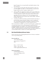
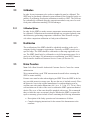
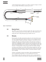
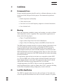
5698
Working Standard
Platinum Resistance Thermometer
User’s Guide
Rev. 272301
Copyright, © 2002. All rights reserved.
Hart Scientific, Inc.
799 E. Utah Valley Drive
American Fork, Utah 84003-9775
Telephone (801) 763-1600 • Fax (801) 763-1010
Internet: http://www.hartscientific.com
E-Mail: [email protected]
Table of Contents
1
Before You Start . . . . . . . . . . . . . . . . . . . . . . . . . . . . . . . . 1
1.1 Symbols Used . . . . . . . . . . . . . . . . . . . . . . . . . . . . . . . . . . . . . . . . . . 1
1.2 Safety Information. . . . . . . . . . . . . . . . . . . . . . . . . . . . . . . . . . . . . . . . 2
1.2.1
1.2.2
Warnings . . . . . . . . . . . . . . . . . . . . . . . . . . . . . . . . . . . . . . . . . . . . . . . . . . . . 2
Cautions. . . . . . . . . . . . . . . . . . . . . . . . . . . . . . . . . . . . . . . . . . . . . . . . . . . . . 3
1.3 Verifying SPRT Accuracy . . . . . . . . . . . . . . . . . . . . . . . . . . . . . . . . . . . . . 3
1.4 Hart Scientific Authorized Service Centers . . . . . . . . . . . . . . . . . . . . . . . . . . . . 4
2
Introduction . . . . . . . . . . . . . . . . . . . . . . . . . . . . . . . . . . 7
2.1 General . . . . . . . . . . . . . . . . . . . . . . . . . . . . . . . . . . . . . . . . . . . . . 7
2.2 Application. . . . . . . . . . . . . . . . . . . . . . . . . . . . . . . . . . . . . . . . . . . . 7
2.3 Calibration . . . . . . . . . . . . . . . . . . . . . . . . . . . . . . . . . . . . . . . . . . . . 8
2.3.1
Calibration Options . . . . . . . . . . . . . . . . . . . . . . . . . . . . . . . . . . . . . . . . . . . . . . . 8
2.4 Recalibration. . . . . . . . . . . . . . . . . . . . . . . . . . . . . . . . . . . . . . . . . . . 8
2.5 Return Procedure . . . . . . . . . . . . . . . . . . . . . . . . . . . . . . . . . . . . . . . . 8
3
Specifications . . . . . . . . . . . . . . . . . . . . . . . . . . . . . . . . . 9
3.1
3.2
3.3
3.4
4
Specifications . . . . . . . . . . . . . . . . . . . . . . . . . . . . . . . . . . . . . . . . . . 9
Construction . . . . . . . . . . . . . . . . . . . . . . . . . . . . . . . . . . . . . . . . . . . 9
Electrical Circuit. . . . . . . . . . . . . . . . . . . . . . . . . . . . . . . . . . . . . . . . . 10
Warranty . . . . . . . . . . . . . . . . . . . . . . . . . . . . . . . . . . . . . . . . . . . . 10
Installation . . . . . . . . . . . . . . . . . . . . . . . . . . . . . . . . . . 13
4.1 Environmental Issues. . . . . . . . . . . . . . . . . . . . . . . . . . . . . . . . . . . . . . 13
4.2 Mounting . . . . . . . . . . . . . . . . . . . . . . . . . . . . . . . . . . . . . . . . . . . . 13
4.3 Lead Wire Identification . . . . . . . . . . . . . . . . . . . . . . . . . . . . . . . . . . . . 13
5
Care and Handling Guidelines. . . . . . . . . . . . . . . . . . . . . . . . 19
5.1
5.2
5.3
5.4
6
SPRT Care . . . . . . . . . . . . .
SPRT Handling Guidelines . . . . .
Metal Ion Contamination of SPRTs .
Devitrification of Fused Silica Glass
.
.
.
.
.
.
.
.
.
.
.
.
.
.
.
.
.
.
.
.
.
.
.
.
.
.
.
.
.
.
.
.
.
.
.
.
.
.
.
.
.
.
.
.
.
.
.
.
.
.
.
.
.
.
.
.
.
.
.
.
.
.
.
.
.
.
.
.
.
.
.
.
.
.
.
.
.
.
.
.
.
.
.
.
.
.
.
.
.
.
.
.
.
.
.
.
.
.
.
.
.
.
.
.
.
.
.
.
.
.
.
.
.
.
.
.
.
.
.
.
19
19
20
21
Operation . . . . . . . . . . . . . . . . . . . . . . . . . . . . . . . . . . 23
6.1 General. . . . . . . . . . . . . . . . . . . . . . . . . . . . . . . . . . . . . . . . . . . . . 23
i
6.2
6.3
6.4
6.5
6.6
7
Comparison Calibration of Other Instruments
Measuring Current . . . . . . . . . . . . . .
Immersion Requirements. . . . . . . . . . .
Thermal EMF . . . . . . . . . . . . . . . . .
Cooling Rates at High Temperatures . . . . .
.
.
.
.
.
.
.
.
.
.
.
.
.
.
.
.
.
.
.
.
.
.
.
.
.
.
.
.
.
.
.
.
.
.
.
.
.
.
.
.
.
.
.
.
.
.
.
.
.
.
.
.
.
.
.
.
.
.
.
.
.
.
.
.
.
.
.
.
.
.
.
.
.
.
.
.
.
.
.
.
.
.
.
.
.
.
.
.
.
.
.
.
.
.
.
.
.
.
.
.
.
.
.
.
.
.
.
.
.
.
.
.
.
.
.
.
.
.
.
.
.
.
.
.
.
23
23
24
24
24
Accessories . . . . . . . . . . . . . . . . . . . . . . . . . . . . . . . . . . 27
7.1 Case. . . . . . . . . . . . . . . . . . . . . . . . . . . . . . . . . . . . . . . . . . . . . . . 27
7.2 SPRT Termination . . . . . . . . . . . . . . . . . . . . . . . . . . . . . . . . . . . . . . . 27
8
Troubleshooting . . . . . . . . . . . . . . . . . . . . . . . . . . . . . . . 29
8.1 Troubleshooting . . . . . . . . . . . . . . . . . . . . . . . . . . . . . . . . . . . . . . . . 29
ii
Figures
Figure 1
Figure 2
Figure 3
Figure 4
Figure 5
Figure 6
5698 Working Standard Platinum Resistance Thermometer . . . . . . . . . . . . . . . . . . . 7
Standard Dimensions. . . . . . . . . . . . . . . . . . . . . . . . . . . . . . . . . . . . . . . 10
Liquid Bath Installation . . . . . . . . . . . . . . . . . . . . . . . . . . . . . . . . . . . . . 14
Water Triple Point Cell in an Ice Bath Dewar. . . . . . . . . . . . . . . . . . . . . . . . . . . 15
Hart 9114 Metrology Furnace with SPRT in Fixed Point Cell. . . . . . . . . . . . . . . . . . . 16
SPRT Circuit Schematic . . . . . . . . . . . . . . . . . . . . . . . . . . . . . . . . . . . . . . 17
iii
Tables
Table 1
iv
International Electrical Symbols . . . . . . . . . . . . . . . . . . . . . . . . . . . . . . . . . . 1
v
1 Before You Start
1
Before You Start
1.1
Symbols Used
Table 1 lists the International Electrical Symbols. Some or all of these symbols
may be used on the instrument or in this manual.
Table 1 International Electrical Symbols
Symbol
Description
AC (Alternating Current)
AC-DC
Battery
CE
DC
Double Insulated
Electric Shock
Fuse
PE Ground
Hot Surface (Burn Hazard)
Read the User’s Manual (Important Information)
Off
On
5698
1
1 Before You Start
Symbol
Description
Canadian Standards Association
CAT II
1.2
OVERVOLTAGE (Installation) CATEGORY II, Pollution Degree 2 per IEC1010-1 refers to
the level of Impulse Withstand Voltage protection provided. Equipment of OVERVOLTAGE
CATEGORY II is energy-consuming equipment to be supplied from the fixed installation.
Examples include household, office, and laboratory appliances.
Safety Information
Use this instrument only as specified in this manual. Otherwise, the protection
provided by the instrument may be impaired.
The following definitions apply to the terms “Warning” and “Caution”.
• “Warning” identifies conditions and actions that may pose hazards to the
user.
• “Caution” identifies conditions and actions that may damage the instrument being used.
1.2.1
Warnings
To avoid personal injury, follow these guidelines.
General
• DO NOT use this instrument for any application other than calibration
work. Use of the instrument outside the designed use may subject the user
to unknown hazards.
• DO NOT use this instrument in environments other than those listed in
the user’s guide. Use of the instrument in inappropriate environments may
subject the user to unknown hazards or damage the instrument.
• Follow all safety guidelines listed in the user’s guide.
• Calibration Equipment should only be used by Trained Personnel.
Electric Shock
• DO NOT use this instrument to measure the temperature of any hazardous live component. Electric shock may occur.
2
Hart Scientific
1 Before You Start
Burn Hazard
• Use of this instrument at high temperatures for extended periods of time
can cause the handle to become hot.
1.2.2
Cautions
• DO NOT remove the label from the handle. The delicate nature of the instrument is described on the label.
• Read Section 5 entitled, “Care and Handling Guidelines”, before removing the SPRT from the shipping box or case. Incorrect handling can damage the SPRT and void the warranty.
• If the SPRT has been calibrated, follow the procedure outlined in Section
1.3, Verifying SPRT Accuracy, (or your quality procedure) for verifying
the accuracy of your SPRT before placing the instrument in service.
• DO NOT subject the SPRT to mechanical shock.
• Use of the SPRT at temperature greater than 500°C requires a specified
minimum cooling rate in order to prevent damage to the SPRT. Refer to
Section 6.6, Cooling Rates at High Temperatures.
• Keep the shipping container in case it is necessary to ship the SPRT. Incorrect packaging of the SPRT for shipment can cause irreparable
damage.
1.3
Verifying SPRT Accuracy
This section is applicable only if the SPRT has been calibrated.
Before using your SPRT, verify that its behavior has not changed significantly
from the most recent calibration (as can sometimes occur from mechanical
shock during shipping, for example). To verify your SPRT, check the SPRT at
the triple point of water (0.01°C) or in a well-constructed ice bath, by following
these steps:
5698
1.
Connect the SPRT to a calibrated readout.
2.
Properly prepare a triple point of water cell (TPW) or ice bath. Ensure
that the SPRT is pre-chilled prior to measurement. (Contact a Hart Scientific Authorized Customer Service Center if unsure how to do this.)
A triple of water cell is preferred. Ice baths should use distilled water
and crushed ice made with distilled water in a Dewar flask or thermos
3
1 Before You Start
bottle. The ratio of ice-to-water should be such that the mixture is firm
after preparation.
3.
Set your readout to read in ohms rather than temperature. Place your
pre-chilled SPRT in the TPW or ice bath and allow it to stabilize. (Remember a TPW is at 0.01°C and an ice bath is at 0°C.)
4.
If using a TPW cell, compare the resistance value on your readout with
the resistance value at TPW given on the probe’s certificate. If using an
ice bath, compare the resistance value on your readout with the resistance indicated on the certificate for 0°C. (You may have to use the
SPRT’s temperature versus resistance table to get the SPRT’s calibrated
resistance value at 0°C.)
5.
Considering the SPRT’s uncertainty specification and the uncertainty of
the thermometer readout, determine whether or not it is within tolerance, as specified in your quality requirements, of the data on its most
recent Report of Calibration. If it is, it may be placed in service.
Hart recommends that an SPRT be periodically checked against a standard such
as a triple point of water cell (or well-constructed ice bath if an ITS-90
fixed-point standard is not available). The verification interval depends on how
the SPRT is handled, how much it is used, and your documented experience
with it. Your probe should also be checked any time you suspect it may have received mechanical shock or whenever its accuracy appears suspect.
1.4
Hart Scientific Authorized Service Centers
Please contact one of the following authorized Service Centers to coordinate
service on your Hart product:
Hart Scientific, Inc.
799 E. Utah Valley Drive
American Fork, UT 84003-9775
USA
Phone: +1.801.763.1600
Telefax: +1.801.763.1010
E-mail: [email protected]
Fluke Nederland B.V.
Customer Support Services
Science Park Eindhoven 5108
5692 EC Son
4
Hart Scientific
1 Before You Start
NETHERLANDS
Phone: +31-402-675300
Telefax: +31-402-675321
E-mail: [email protected]
Fluke Int'l Corporation
Service Center - Instrimpex
Room 2301 Sciteck Tower
22 Jianguomenwai Dajie
Chao Yang District
Beijing 100004, PRC
CHINA
Phone: +86-10-6-512-3436
Telefax: +86-10-6-512-3437
E-mail: [email protected]
Fluke South East Asia Pte Ltd.
Fluke ASEAN Regional Office
Service Center
83 Clemenceau Avenue
#15-15/06 Ue Square
239920
SINGAPORE
Phone: +65-737-2922
Telefax: +65-737-5155
E-mail: [email protected]
When contacting these Service Centers for support, please have the following
information available:
• Model Number
• Serial Number
• Complete description of the problem
5698
5
2 Introduction
2
Introduction
2.1
General
The Hart Standard Platinum Resistance Thermometer (SPRT) is designed to be
the best primary standard interpolating instrument converting resistance to
temperature. With full calibration options, ITS-90 coefficients can be used with
your 1590, 1560, or 1529 Hart thermometer readout. With drift rate typically
around ±3 mK, this SPRT gets you from –200°C up to 661°C.
The 5698 is hand constructed at Hart by experts with years of SPRT manufacturing experience. Each SPRT is carefully annealed at the appropriate temperatures and precisely tested for stability. Convection prevention discs are used to
reduce stem errors caused by thermal radiation. The sensing element is
fabracated using high purity platinum wire wound in a strain free design on a
fused silica cross frame. A fused silica sheath is pressure sealed with a special
argon/oxygen mixed gas and fitted with a terminal box handle with a strain relieved connection to the four wire cable. Gold plated spade lugs terminate the
wires.
2.2
Application
The 5698 SPRT is a working standard. A working standard is defined in terms
of transfer of the ITS-90 from a standards laboratory to a customer’s laboratory.
Working standards are calibrated in a standards lab using known intrinsic
values.
Figure 1 5698 Working Standard Platinum Resistance Thermometer
5698
7
2 Introduction
2.3
Calibration
In order for any instrument to be used as a standard it must be calibrated. The
SPRT may be purchased calibrated or non-calibrated. Hart Scientific has the capability of performing fixed-point calibrations traceable to NIST. The 5698 can
be economically calibrated using the comparison method or any one of several
fixed point calibrations matching ITS-90 subranges.
2.3.1
Calibration Options
In order for the SPRTs to make accurate temperature measurements, they must
be calibrated. Calibration can be attained through any recognized primary standard laboratory performing temperature calibrations. Hart Scientific can provide either comparison calibration or fixed-point calibrations.
2.4
Recalibration
The recalibration of the SPRTs should be scheduled according to the user’s
company Quality Assurance requirements. Generally, an SPRT is used over a
specific range. The SPRT should be calibrated over the range applicable to its
use. The SPRT should only be calibrated over its full temperature range if it is
used over its full range. For information on recalibrating your SPRT, contact a
Hart Scientific Authorized Customer Service Center (see Section 1.4).
2.5
Return Procedure
Note: Call a Hart Scientific Authorized Customer Service Center for a return
authorization.
We recommend that a good TPW measurement be made before returning the
SPRT to ensure stability.
Extreme care must be taken when shipping an SPRT. Place the SPRT in the factory provided protective storage case. Be sure the case is latched securely. Place
the protective case in the original manufacturer’s wooden shipping crate or
wooden crate with similar dimensions (44 ½ in. x 11 3/4 in. x 11 3/4 in.). Place
soft insulation on all sides of the crate to cushion the SPRT against mechanical
shocks. The cover of the crate should be attached with screws. We recommend
that you label the crate as extremely fragile. Whether the SPRT is returned for
repair or warranty, please include a letter containing the following information
• Description of the faulty operation and circumstances of failure.
• Complete shipping instructions for the return of the thermometer to the
customer.
8
Hart Scientific
3 Specifications
3
Specifications
3.1
Specifications
3.2
Temperature Range
–200°C to 661°C
Nominal RTPW
25.5Ω (±0.5Ω)
Current
1.0 mA
Resistance Ratios
W(234.315K) ≤ 0.844235
W(302.9146K) ≥ 1.11807
Sensitivity
0.1Ω/°C
Drift Rate
<0.006°C/100 hours at max temperature (typically < 0.003°C)
Diameter of Pt Sensor
Wire
Protective Sheath
0.003" (0.07 mm)
Lead Wires
Four sensor wires
Fused Silica Glass
Diameter: 0.28" (7 mm)
Length: 19.1" (485 mm)
Construction
Construction of the 5698 is shown in Figure 2 and explained below.
The 5698 covers the range from –200°C to 661°C. The 25.5Ω sensor element is
5698
9
3 Specifications
crafted using high purity platinum wire wound in a strain free design on a fused
silica cross frame. The 5698 has a sensitivity of 0.1Ω/°C.
3.5"
(89 mm)
Strain Relief
19.1"
(485 mm)
Protecting Tube
Terminal Box
(Fused Silica)
.28"
(7 mm)
Terminal
(Gold-Plated)
Lead Wire
85"
(2159 mm)
6"
(152 m
m)
Figure 2 Standard Dimensions
3.3
Electrical Circuit
The SPRT is provided with a terminal box handle. The eight-foot cable has four
Teflon_coated wires enclosed in a silicon rubber jacket with a stainless steel
spring strain relief. Gold plated spade lugs terminate the wires.
3.4
Warranty
Hart Scientific, Inc. (Hart) warrants this product to be free from defects in material and workmanship under normal use and service for a period as stated in
our current product catalog from the date of shipment. If your SPRT was calibrated by Hart, Hart also warrants the validity of the data on the certificate of
calibration accompanying your probe. However, because probes are subject to
change from mishandling, vibration, and other forms of mechanical shock, Hart
does not warrant the behavior of your probe once it has left Hart’s control. (See
Section 1.3, Verifying Probe Accuracy, for procedures for initially checking
your probe upon receipt at your facility.)This warranty extends only to the original purchaser and shall not apply to any product which, in Hart’s sole opinion,
has been subject to misuse, alteration, abuse or abnormal conditions of operation or handling.
Software is warranted to operate in accordance with its programmed instructions on appropriate Hart products. It is not warranted to be error free.
Hart’s obligation under this warranty is limited to repair or replacement of a
product which is returned to Hart within the warranty period and is determined,
10
Hart Scientific
3 Specifications
upon examination by Hart, to be defective. If Hart determines that the defect or
malfunction has been caused by misuse, alteration, abuse or abnormal conditions or operation or handling, Hart will repair the product and bill the purchaser for the reasonable cost of repair.
To exercise this warranty, the purchaser must forward the product after calling
or writing a Hart Scientific Authorized Service Center for authorization (see
Section 1.4). The Service Center assumes NO risk for in-transit damage.
THE FOREGOING WARRANTY IS PURCHASER’S SOLE AND EXCLUSIVE REMEDY AND IS IN LIEU OF ALL OTHER WARRANTIES, EXPRESS OR IMPLIED, INCLUDING BUT NOT LIMITED TO ANY IMPLIED
WARRANTY OR MERCHANTABILITY, OR FITNESS FOR ANY PARTICULAR PURPOSE OR USE. HART SHALL NOT BE LIABLE FOR ANY
SPECIAL, INDIRECT, INCIDENTAL, OR CONSEQUENTIAL DAMAGES
OR LOSS WHETHER IN CONTRACT, TORT, OR OTHERWISE.
5698
11
4 Installation
4
Installation
4.1
Environmental Issues
Primary standard equipment should be used in a calibration laboratory or other
facility specifically designed for this purpose. Environmental requirements
include:
• Stable temperature and humidity.
• Clean, draft-free area.
• Low noise level: low radio frequency, magnetic or electrical interference.
• Low vibration levels
4.2
Mounting
Most often temperature standards, primary and secondary, are used to calibrate
other temperature-sensitive equipment. Three representative applications are
shown in the following figures.
• Figure 3 Liquid Bath Installation
• Figure 4 Water Triple Point Cell in an Ice Bath Dewar
• Figure 5 Hart 9114 Metrology Furnace with SPRT in Fixed Point Cell
The SPRT must be mounted carefully to avoid any damage to the sheath or sensor. If the fluid bath used does not have a lid designed for SPRT insertion,
clamps should be used to ensure the handle and cable are not immersed. If
metal comparison blocks are used in the bath, maintain a close fit between the
SPRT sheath and the well in the comparison block. However, allow for the thermal expansion and contraction of the SPRT sheath and block when determining
block well tolerances.
For applications where the fluid in the bath is not compatible with the SPRT
(e.g. salt), the SPRT can be slid into a thin walled metal sheath for protection.
Ensure that the sheath is clean inside. The gap between the protective sheath
and the SPRT should not be any larger than 0.003 in. (0.08 mm).
At high temperatures, the SPRT is subject to metal ion contamination. If a
metal equilibration block is used in a furnace above 700°C, protective shielding
such as thin wall platinum tubing or high purity ceramic is advised.
4.3
Lead Wire Identification
The SPRT is equipped with a four-wire cable (see Figure 6). Four lead wires
are used to prevent measurement errors due to lead wire resistance. For proper
5698
13
4 Installation
24"
7007 Tank with
Long Stem SPRTs
Figure 3 Liquid Bath Installation
14
Hart Scientific
4 Installation
SPRT
Precooling
Access Hole
Lid
Thermometer
Guide Tube
Water Vapor
Dewar
Flask
Borosilicate
Glass
Reentrant
Thermometer Well
Water from
or Alcohol
Ice
Bath
Water
Solid (Ice)
Water
Liquid
Metal
Bushing
Soft
Pad
Ice Bath or
Maintenance Bath
Cushion
Outer
Canister
Figure 4 Water Triple Point Cell in an Ice Bath Dewar
5698
15
4 Installation
SPRT
Thermal Guard Assembly
Main Controller
SPRT Equilibration
Block
PRT Sensor
419.03 C
SET
DOWN
UP
EXIT
Top Zone
Heater
Top Zone
Controller
419.03 C
SET
DOWN
UP
TOP END ZONE
EXIT
Main Heater
Differential TCs
Freeze-Point
Cell
PRIMARY ZONE
Cell Support
Container
Differential TCs
Thermal Block
(3 zone subdivision)
Bottom Zone
Controller
419.03 C
SET
DOWN
UP
EXIT
BOTTOM END ZONE
Bottom Zone
Heater
Water Cooling
Coils
Supercooling
Gas Supply
(Argon)
Figure 5 Hart 9114 Metrology Furnace with SPRT in Fixed Point Cell
16
Hart Scientific
4 Installation
measurement, the readout device should be equipped to handle four-terminal
resistors.
The lead wire colors are red, black, white, and blue. Lead wire pairs attached to
each end of the sensor are identified by heat shrink tubing. Red and black wires
have red heat shrink tubing. Blue and white wires have black heat shrink tubing
(see Figure 6 for details).
The circuit is connected in true four terminal configuration. Therefore, there is
no distinction between voltage (sense) and current (source) leads.
White
Red
BLACK
RED
Blue
Black
Rx
Figure 6 SPRT Circuit Schematic
5698
17
5 Care and Handling Guidelines
5
Care and Handling Guidelines
Caution: Read before removing the SPRT from the case.
5.1
SPRT Care
The 5698 Standard Platinum Resistance Thermometer (SPRT) is an extremely
delicate instrument. Great care must be taken in handling the SPRT to maintain
calibration accuracy. Vibration or shock may cause the resistance to increase. A
slight tap to the SPRT tip as it is removed from an instrument can cause a
change in Rtpw as high as 1 mK. At high temperatures, the SPRT may become
contaminated if inserted into metal blocks. This contamination can effect the
condition of the sensor if the contamination invades the sensor degrading the
purity of the platinum wire. The fused silica sheath is very fragile and also susceptible to contamination. Once a SPRT is contaminated, it can contaminate
other standards equipment. (Copper contamination shows as red smudged on
the sheath.) Any contamination can cause devitrification of the sheath at high
temperatures. The fused silica sheath should not be handled with bare hands.
Cotton gloves or other suitable methods should be used in handling the SPRT.
The sheath should always be cleaned with 200 proof Ethyl Alcohol or other
suitable solvent before exposure to high temperatures. Correct handling of
the SPRT will prolong the life expectancy. When not in use, the SPRT should
be stored in its protective case.
5.2
5698
SPRT Handling Guidelines
1.
DO keep the SPRT as clean as possible. Always remove any fluid from
the sheath as soon as possible after taking the SPRT from a bath. Ensure that the fluid and SPRT have cooled sufficiently to prevent a safety
hazard. To remove any possible contaminants, always wipe the sheath
with ethyl alcohol or other solvent before submitting the SPRT to high
temperatures.
2.
DO immerse the SPRT in the appropriate liquid for the temperature
range. If a dry block is used, the well diameter should allow the SPRT
to comfortably slip in and out without excess movement. For best results, immerse the SPRT as deep as possible to avoid “stem effect” (the
temperature error caused by the conduction of heat away from the sensor). Do not submerge the handles.
3.
DO allow sufficient time for the SPRT to stabilize before making measurements. This allows for the best accuracy.
4.
DO use the correct drive current with the SPRT to prevent error in temperature or resistance.
19
5 Care and Handling Guidelines
5.3
5.
DO anneal the SPRT at a temperature slightly higher than the maximum temperature at which the thermometer will be used when it has
been subjected to mechanical or temperature shock. The SPRT should
also be annealed before calibration. The SPRT should be annealed at
675°C.
6.
DO use the protective case provided or other protection when the thermometer is not in use.
7.
DON’T subject the thermometer to any physical shock or vibration.
8.
DON’T subject the thermometer to temperatures above the highest
specified operating temperature.
9.
DON’T expose the thermometer’s handle or cables to extreme temperatures.
10.
DON’T submerge the handle or cable in liquids.
Metal Ion Contamination of SPRTs
Since the acceptance of ITS-90, information has been accumulating about contamination of SPRTs. ITS-90 extended the range of the SPRT as an interpolation device and new problems manifested themselves. Metal ion contamination
is one of the new problems and can start at approximately 700°C.
At high temperatures the lattice structure of most metals becomes open. This
allows energetic metal ions to come off the surface, analogous to steam rising
from hot water. Since the molecular activity increases with temperature, so does
the amount of ion loss and the risk of contamination. Ion transfer occurs at different temperatures for different metals. Copper, nickel, iron, and manganese
are metals that have been attributed to causing contamination. In addition, the
fused silica lattice structure also becomes open at these high temperatures. This
allows the fused silica to become transparent to these metal ions permitting the
transfer of these ions from adjacent metal surfaces to the pure platinum wire of
the SPRT sensor. The contaminated platinum behaves unpredictably, resulting
in a loss of stability and calibration.
Contamination can be spread by an “infected” SPRT to other primary standards
analogous to a virus. Therefore, it is very important to avoid contamination as
much as possible to ensure the longevity of the SPRT itself and to decrease the
spread to other standards.
Isolation of sensitive materials can prevent contamination. Pure platinum foil is
being used by some experts to intercept the ions before they reach the SPRT.
Silicon carbide is also used by some experts to shield the SPRT because it is
less expensive than platinum foil. Information on contamination effects and
prevention is still being gathered by experts in the field.
20
Hart Scientific
5 Care and Handling Guidelines
5.4
Devitrification of Fused Silica Glass
Devitrification is a natural process with quartz materials. The fused silica is utilized in a glass (non-crystalline) state. The most stable state for fused silica is
crystalline. Therefore, devitrification is the tendency of the fused silica to return
to its most stable state. If the fused silica is kept extremely clean and free of
contamination, devitrification occurs only at high temperatures. The process occurs more rapidly and at lower temperatures when the glass is contaminated by
alkaline metals (Na, K, Mg, and Ca). The alkalis found in normal tap water can
trigger the process.
Note: There is conflicting opinion among the experts as to whether the process
can be stopped. Some say that once the process starts, it does not stop. Others
indicate that once the alkali is removed, the process of devitrification stops.
Removal of the devitrification is not practical as it requires drastic measures
and is potentially dangerous to the instrument and/or the user.
Devitrification starts with a dulling or opacity of the fused silica sheath. It develops into a rough and crumbling surface. Devitrification ultimately weakens
the fused silica until it breaks or is otherwise no longer useful.
The best cure for contamination and devitrification is prevention. Being aware
of the causes and signs of contamination can help the user take the steps necessary to control contamination of the SPRT. Keep your SPRT clean and avoid
contact with metals at temperatures above 700°C.
5698
21
6 Operation
6
Operation
6.1
General
For best results, be familiar with the operation of the calibration bath or furnace
and the readout instrument. Be sure to follow the manufacturer’s instructions
for the readout instrument and the calibration bath or furnace.
6.2
Comparison Calibration of Other Instruments
The uniformity and stability of the bath and the degree of accuracy required determine the number of temperature measurements necessary. However, to follow “good” practice procedures, always measure the triple point of water (Rtp)
after each temperature measurement. This provides the most accurate measurement of the ratio:
Wt =
6.3
Rt
Rtp
Measuring Current
The 5698 SPRT has a specified drive current. The recommended current is
listed in the specifications and below.
Suggested Drive Current
Model
Resistance
Drive Current
5698
25Ω
1 mA
Errors caused by self-heating of the element need to be minimized. Allowing
sufficient time for the SPRT to stabilize and the heat to be dispersed into the
surrounding medium will provide the most accurate results.
The Report of Calibration provided with the SPRT represent data that has been
extrapolated. For example, on a 5698 measurements are made at 1 mA and 1.4
mA. These measurements are then extrapolated to zero current. This can be
done graphically by plotting i² vs. R and extrapolating to zero power or by using the following equation:
R0 = R1 −
i12 ( R2 − R1 )
i22 − i12
where:
R0 = Zero current resistance
R1 = Resistance measured at current i1
5698
23
6 Operation
R2 = Resistance measured at current i2
6.4
Immersion Requirements
Stem effect can cause measurement errors for SPRTs not immersed in the fluid
at least six inches. This error is due to heat lost or gained by the sensing element through the thermometer stem. In addition, heat losses occur due to radiation losses from the sensing element to the housing. The sand-blasted finish on
the fused silica sheath is designed to mimimize losses due to radiation piping.
Convection prevention discs also provide multiple radiation shields along the
lead wires. Convection discs and the quartz insulation on lead wires cause some
shunt resistance at very high temperatures. However, the effect of the shunt resistance is insignificant. Full immersion is recommended in a furnace or freeze
point cell.
The immersion depth for primary standards is dependent on several factors including accuracy requirements and type of liquid. Therefore, we recommend an
8 inch minimum immersion depth.
The exact immersion depth required can be determined by performing a gradient test taking measurements approximately every 1/2 inch (1.27 cm) until
there is a significant difference in readings. Allow the thermometer to stabilize
at each new depth. Plot the results to see the stem effect.
6.5
Thermal EMF
Two factors contribute to thermal EMF, chemical consistency and physical consistency. Variations in chemical structure due to impurities and discrepancies in
crystal structure can contribute to thermal EMF. These factors are minimized by
annealing the full length of wire before construction of the SPRT.
Likewise, connection to extension lead wires and readout instruments can be a
source of thermal EMF. The thermal EMF is caused by a difference in temperature between two connections. If the two connections are the same temperature,
there will be little or no thermal EMF effects. However, if there is a substantial
temperature difference between connections, the thermal EMF effects will be
significant. Therefore, cover or insulate any exposed bridge or galvanometer
terminals to lessen the source of error. The effects of thermal EMF can be
reduced by using an AC bridge or a DC bridge with reversible current.
6.6
Cooling Rates at High Temperatures
The equilibrium concentration of point defects in the pure platinum wire increase exponentially to the increase in temperature. If a high cooling rate (i.e.,
removing a SPRT from a high temperature and cooling it to room temperature
in less than a minute) occurs above 500°C, some of the point defects in the platinum wire become trapped in the crystalline structure causing a slight increase
24
Hart Scientific
6 Operation
in resistance. This slight increase in resistance can be reversed by annealing the
SPRT. To avoid this problem, slowly cool the SPRT at a rate of roughly
150°C/hour above 500°C before removing to room temperature.
The SPRT can be safely removed from an instrument at 500°C or less and
cooled to room temperature without concern for the cooling rate.
5698
25
7 Accessories
7
Accessories
7.1
Case
The SPRTS are shipped in a protective case. The SPRT should be stored in this
case when not in use. The SPRT should be shipped in this case when returning
(see Section 2.5, Return Procedure).
7.2
SPRT Termination
The 5698 SPRTs are terminated with gold plated lugs.
5698
27
8 Troubleshooting
8
Troubleshooting
8.1
Troubleshooting
In the event that the SPRT appears to function abnormally, this section may
help to find and solve the problem. Several possible problem conditions are described along with likely causes and solutions. If a problem arises, read this
section carefully and attempt to understand and solve the problem. If the SPRT
seems faulty or the problem cannot otherwise be solved, contact a Hart Scientific Authorized Service Center for assistance (see Section 1.4).
Problem
Solution
Data changes
Slight mechanical shock can cause temperature errors as much as
2mK. If this is observed, first measure and record the Rtpw. Next anneal the
SPRT at 675°C overnight (12 hours). Measure the Rtpw again. The annealing
should decrease the Rtpw. Repeat the annealing, Rtpw measurement cycle several times. If the RTPW returns to the proper value, the SPRT may be returned
to service. If the SPRT does not returen to the proper RTPW value but is stable,
return for recalibration. When the Rtpw is stable, recalibrate the SPRT. If the
Rtpw does not stabilize, contact a Hart Scientific Authorized Service Center for
assistance (see Section 1.4.)
Severe mechanical shock can permanently damage the SPRT. If annealing the SPRT does not resolve the data change, contact a Hart Scientific
Authorized Service Center for assistance (see Section 1.4).
Oxidation of the platinum sensor may occur after prolonged use between 200 and 450°C. Rtpw will show an increase. To reduce the effects of
oxidation, anneal the SPRT at the appropriate temperature as described
above. Measure the Rtpw again. Repeat the annealing, Rtpw measurement cycle
several times. This annealing process should return Rtpw to within calibration
tolerances. If the Rtpw is within calibration tolerance, the SPRT is usable. If the
Rtpw is not within calibration tolerance, but it is stable, recalibrate the SPRT.
Data unstable
Connection may not be made. If the data is unstable at the Triple Point of
Water (TPW), check the connection first. If this action does not fix the problem
contact a Hart Scientific Authorized Service Center for assistance (see Section
1.4). The SPRT may be damaged and need repair.
Electrical noise in the system. If the data is unstable at high temperatures, it may be due to electrical noise in the system. Reduce the temperature
and observe the data. If it is stable, electrical noise is interfering with the
measurements at high temperatures. Check the grounding of the readout device and the heat source. A faulty ground on either device could interfere with
high temperature measurements.
5698-25
29
8 Troubleshooting
30
Problem
Solution
Temperature readout different
than expected, e.g. the heat
source is set at 300°C, the SPRT
measures 275°C
Measure the SPRT resistance at TPW. If the resistance of the SPRT is less
than the rated resistance, there may be a short in the sensor. If the resistance
of the SPRT is only a few ohms, there may be a short in the four lead-wires. If
the SPRT is open, the resistance will be “Out of Limits” or in the kilo-ohm or
mega-ohm range. Contact a Hart Scientific Authorized Service Center for assistance (see Section 1.4)
Hart Scientific