1
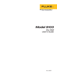
9101 Zero Point
Dry-Well
User Manual
Rev. 4A0801
Hart Scientific, LLC • 799 E. Utah Valley Drive • American Fork, UT 84003-9775 • USA
Phone: +1.801.763.1600 • Telefax: +1.801.763.1010 • E-mail: [email protected]
www.hartscientific.com
Subject to change without notice. • Copyright © 1991 • Printed in USA
Rev. 4A0801
Table of Contents
1 Before You Start . . . . . . . . . . . . . . . . . . . . . . 1
1.1
1.2
Symbols Used . . . . . . . . . . . . . . . . . . . . . . . . . 1
Safety Information . . . . . . . . . . . . . . . . . . . . . . . 2
1.2.1
1.2.2
1.3
Warnings . . . . . . . . . . . . . . . . . . . . . . . . . . . . . . . . 2
Cautions . . . . . . . . . . . . . . . . . . . . . . . . . . . . . . . . . 3
Hart Scientific Authorized Service Centers . . . . . . . . . . . 3
2 Introduction . . . . . . . . . . . . . . . . . . . . . . . . 5
3 Specifications and Environmental Conditions . . . . . . 7
3.1
3.2
Specifications . . . . . . . . . . . . . . . . . . . . . . . . . 7
Environmental Conditions . . . . . . . . . . . . . . . . . . . 7
3.3
Warranty . . . . . . . . . . . . . . . . . . . . . . . . . . . . 8
4 Quick Start . . . . . . . . . . . . . . . . . . . . . . . . 9
4.1
4.2
Unpacking . . . . . . . . . . . . . . . . . . . . . . . . . . . 9
Set up . . . . . . . . . . . . . . . . . . . . . . . . . . . . . 9
4.3
Power . . . . . . . . . . . . . . . . . . . . . . . . . . . . . 9
5 General Operation . . . . . . . . . . . . . . . . . . . . 11
5.1
5.2
Set up. . . . . . . . . . . . . . . . . . . . . . . . . . . . . 11
Cooling . . . . . . . . . . . . . . . . . . . . . . . . . . . . 11
5.3
Measurement . . . . . . . . . . . . . . . . . . . . . . . . . 11
6 Test Probe Calibration . . . . . . . . . . . . . . . . . . 13
6.1
Calibration Methods . . . . . . . . . . . . . . . . . . . . . 13
6.1.1
6.1.2
6.2
Comparison Calibration. . . . . . . . . . . . . . . . . . . . . . . . . 13
Calibration of Multiple Probes . . . . . . . . . . . . . . . . . . . . . 14
Dry-Well Characteristics . . . . . . . . . . . . . . . . . . . 14
6.2.1
6.2.2
Vertical Gradient . . . . . . . . . . . . . . . . . . . . . . . . . . . . 14
Stabilization and Accuracy . . . . . . . . . . . . . . . . . . . . . . . 14
7 Calibration Procedure . . . . . . . . . . . . . . . . . . 15
8 Maintenance . . . . . . . . . . . . . . . . . . . . . . . 17
9 Troubleshooting . . . . . . . . . . . . . . . . . . . . . 19
i
1
Before You Start
1
1.1
Before You Start
Symbols Used
Table 1 lists the International Electrical Symbols. Some or all of these symbols may be used on the instrument or in this manual.
Table 1 International Electrical Symbols
Symbol
Description
AC (Alternating Current)
AC-DC
Battery
CE Complies with European Union Directives
DC
Double Insulated
Electric Shock
Fuse
PE Ground
Hot Surface (Burn Hazard)
Read the User’s Manual (Important Information)
Off
On
1
9101
User’s Guide
Symbol
Description
Canadian Standards Association
CAT
OVERVOLTAGE (Installation) CATEGORY II, Pollution Degree 2 per
IEC1010-1 refers to the level of Impulse Withstand Voltage protection
provided. Equipment of OVERVOLTAGE CATEGORY II is energy-consuming equipment to be supplied from the fixed installation. Examples include household, office, and laboratory appliances.
C-TIC Australian EMC Mark
1.2
Safety Information
Use this instrument only as specified in this manual. Otherwise, the protection provided by the instrument may be impaired.
The following definitions apply to the terms “Warning” and “Caution”.
• “Warning” identifies conditions and actions that may pose hazards to
the user.
• “Caution” identifies conditions and actions that may damage the instrument being used.
1.2.1
Warnings
To avoid personal injury, follow these guidelines.
• Before initial use, or after transport, or after storage in humid or
semi-humid environments, or anytime the instrument has not been energized for more than 10 days, the instrument needs to be energized
for a “dry-out” period of 2 hours before it can be assumed to meet all of
the safety requirements of the IEC 1010-1. If the product is wet or has
been in a wet environment, take necessary measures to remove moisture prior to applying power such as storage in a low humidity temperature chamber operating at 50 degree centigrade for 4 hours or more.
• Use only a grounded AC mains supply of the appropriate voltage to
power the instrument. The dry-well requires a maximum of 1 amp,
50/60 Hz, 115/230 VAC (±10%).
• DO NOT connect this unit to a non-grounded, non-polarized outlet.
• DO use a ground fault interrupt device.
• HIGH VOLTAGE is used in the operation of this equipment. SEVERE
INJURY or DEATH may result if personnel fail to observe safety precautions. Before working inside the equipment, turn power off and disconnect power cord.
• DO NOT use this unit in environments other than those listed in the
user’s manual.
2
1
Before You Start
• DO NOT use this unit for any application other than calibration work.
• Follow all safety guidelines listed in the user’s manual.
• Calibration Equipment should only be used by Trained Personnel.
1.2.2
Cautions
To avoid possible damage to the instrument, follow these guidelines.
• Operate the instrument in room temperatures between 5-50°C
(41-122°F). Allow sufficient air circulation by leaving at least 6 inches
of space between the instrument and nearby objects. Overhead clearance needs to allow for safe and easy insertion and removal of probes
for calibration.
• The dry-well is a precision instrument. Although it has been designed
for optimum durability and trouble free operation, it must be handled
with care. The instrument should not be operated in excessively wet,
oily, dusty, or dirty environments. It is important to keep the wells of
the instrument clean and clear of any foreign matter. Do not operate
near flammable materials.
• DO NOT use fluids to clean out the well.
• If a mains supply power fluctuation occurs, immediately turn off the instrument. Power bumps from brown-outs and black-outs could damage
the instrument. Wait until the power has stabilized before re-energizing the instrument.
1.3
Hart Scientific Authorized Service
Centers
Please contact one of the following authorized Service Centers to coordinate
service on your Hart product:
Hart Scientific, Inc.
799 E. Utah Valley Drive
American Fork, UT 84003-9775
USA
Phone: +1.801.763.1600
Telefax: +1.801.763.1010
E-mail: [email protected]
Fluke Nederland B.V.
Customer Support Services
Science Park Eindhoven 5108
3
9101
User’s Guide
5692 EC Son
NETHERLANDS
Phone: +31-402-675300
Telefax: +31-402-675321
E-mail: [email protected]
Fluke Int'l Corporation
Service Center - Instrimpex
Room 2301 Sciteck Tower
22 Jianguomenwai Dajie
Chao Yang District
Beijing 100004, PRC
CHINA
Phone: +86-10-6-512-3436
Telefax: +86-10-6-512-3437
E-mail: [email protected]
Fluke South East Asia Pte Ltd.
Fluke ASEAN Regional Office
Service Center
83 Clemenceau Avenue
#15-15/06 Ue Square
239920
SINGAPORE
Phone: +65-737-2922
Telefax: +65-737-5155
E-mail: [email protected]
When contacting these Service Centers for support, please have the following information available:
• Model Number
• Serial Number
• Voltage
• Complete description of the problem
4
2
Introduction
2
Introduction
The Hart model 9101 zero point dry-well is a precision instrument which
maintains a constant temperature at 0°C. It can be used to provide a stable
zero reference for thermocouples or for calibrating temperature probes.The
9101 has three wells so that multiple probes may be calibrated and compared at once.
The 9101 uses solid-state electronics to control the temperature of an aluminum block. The block temperature is monitored with a high sensitivity thermistor sensor. The controlling circuit adjusts the current to thermoelectric
modules which cool the block maintaining a stable temperature. Since the
current to the cooling modules is constant DC there is no problem with induced EMF noise in the user’s probes or thermocouples due to switching
Figure 1 9101 Zero Point Calibrator
5
9101
User’s Guide
transients of the cooling circuits. Because the temperature control is done
with solid-state electronics the 9101 is rugged and stable. The zero point
dry-well will not be damaged by subfreezing temperatures during shipping
or storage.
The 9101 is calibrated at the factory for NIST traceable accuracy. It may also
be easily calibrated in the field to the user’s own standard.
6
3
Specifications and Environmental Conditions
3
3.1
3.2
Specifications and Environmental
Conditions
Specifications
Temperature
0°C
Accuracy
±0.02°C typical, ±0.05°C maximum (18°C–25°C ambient)
Stability
±0.005°C
Temperature
Coefficient
±0.005°C/°C amb.
Stabilization
Time
Approximately 30 minutes (the ready lamp indicates stable control at
0°C)
Operable
temperature
range
5 to 27°C, 40 to 80°F
Accuracy
temperature
range
18 to 25°C, 64 to 77°F
Cooling time:
15 to 30 min., Depending on ambient
Well
3 wells, 2 outside wells .25" dia. X 6" deep, center well .280" dia x
6" deep
Power
115 VAC (±10%)1 A or 230 VAC (±10%) 0.5 A, 50/60 Hz, 125 W
Dimensions
12.25"H x 8.5”W x 5.75"D (311 x 216 x 146 mm)
Environmental Conditions
Although the instrument has been designed for optimum durability and
trouble-free operation, it must be handled with care. The instrument should
not be operated in an excessively dusty or dirty environment. Maintenance
and cleaning recommendations can be found in the Maintenance Section of
this manual.
The instrument operates safely under the following conditions:
• temperature range: 5–50°C (41–122°F)
• ambient relative humidity: maximum 80% for temperature <31°C, decreasing linearly to 50% at 40°C
• pressure: 75kPa–106kPa
• mains voltage within ±10% of nominal
• vibrations in the calibration environment should be minimized
• altitude does not effect the performance or safety of the unit
7
9101
User’s Guide
3.3
Warranty
Hart Scientific, Inc. (Hart) warrants this product to be free from defects in
material and workmanship under normal use and service for a period as
stated in our current product catalog from the date of shipment. This warranty extends only to the original purchaser and shall not apply to any
product which, in Hart's sole opinion, has been subject to misuse, alteration,
abuse or abnormal conditions of operation or handling.
Software is warranted to operate in accordance with its programmed instructions on appropriate Hart products. It is not warranted to be error free.
Hart's obligation under this warranty is limited to repair or replacement of a
product which is returned to Hart within the warranty period and is determined, upon examination by Hart, to be defective. If Hart determines that
the defect or malfunction has been caused by misuse, alteration, abuse or
abnormal conditions or operation or handling, Hart will repair the product
and bill the purchaser for the reasonable cost of repair.
To exercise this warranty, the purchaser must forward the product after calling or writing a Hart Scientific Authorized Service Center (see Section 1.3)
for authorization. The Service Centers assume NO risk for in-transit damage.
THE FOREGOING WARRANTY IS PURCHASER'S SOLE AND EXCLUSIVE REMEDY AND IS IN LIEU OF ALL OTHER WARRANTIES, EXPRESS OR IMPLIED,
INCLUDING BUT NOT LIMITED TO ANY IMPLIED WARRANTY OR
MECHANTABILITY, OR FITNESS FOR ANY PARTICULAR PURPOSE OR USE.
HART SHALL NOT BE LIABLE FOR ANY SPECIAL, INDIRECT, INCIDENTAL, OR
CONSEQUENTIAL DAMAGES OR LOSS WHETHER IN CONTRACT, TORT, OR
OTHERWISE.
8
4
Quick Start
4
4.1
Quick Start
Unpacking
Unpack the dry-well carefully and inspect it for any damage that may have
occurred during shipment. If there is shipping damage, notify the carrier
immediately.
Verify that the following components are present:
• 9101 Dry-well
• 2130, Well tube sizing kit
• Power Cord
• User’s Guide
• Report of Calibration
• Calibration Label
4.2
Set up
Place the 9101 zero point dry-well upright on a flat stable surface. The area
around the instrument must be clear to allow adequate air circulation. For
best results operate the dry-well in room of constant temperature between
18 to 25°C (64 to 77°F) free from drafts. Stable ambient temperatures allow
stable well gradients and less drift.
Turn on the power to the calibrator by toggling the power switch on. The
fan should begin quietly blowing air through the instrument. The amber
LED will light when the unit is energized. The green LED will light when
the unit is ready to use. The unit is not at the correct temperature until the
green LED is illuminated.
4.3
Power
Connect the power cord provided into the instrument and plug the other
end into a power socket of specified voltage. Normally this will be 115 VAC,
+10%, 50/60 Hz. If specified upon ordering the instrument may optionally
be configured to operate at 230 VAC (±10%).
9
5
General Operation
5
5.1
General Operation
Set up
Place the 9101 zero point dry-well upright on a flat stable surface. The area
around the instrument must be clear to allow adequate air circulation. For
best results operate the dry-well in room of constant temperature between
18 to 25°C (64 to 77°F) free from drafts. Stable ambient temperatures allow
stable well gradients and less drift.
5.2
Cooling
Turn on power by pressing the switch on the top of the instrument to the on
position. Notice that the amber POWER indicator light turns on and the fan
begins circulating air. The dry-well will begin to cool the well until it
reaches 0°C and stabilizes. Typically it takes 15 to 30 minutes for the block
to reach 0 and stabilize, longer at higher ambient temperatures. When the
block has reached 0 and stabilized the green READY indicator light will turn
on and the instrument is ready for use.
5.3
Measurement
When the instrument is ready insert the probe into one of the three well
holes at the top of the instrument. The probe should be inserted the full
depth of the well since the temperature is most accurate at the bottom. The
probe must make good contact with the bottom of the well. A little heat
conduction grease on the probe may help. It also helps to apply a small
constant sideways and downwards force on the probe. After inserting the
probe allow approximately 10 minutes for the temperature to stabilize. At
this point the probe may be measured for accuracy or used as a stable zero
reference.
11
6
Test Probe Calibration
6
Test Probe Calibration
For optimum accuracy and stability, allow the calibrator to warm up for 10
minutes after power-up and then allow adequate stabilization time after
reaching the set-point temperature. After completing calibration, allow the
block to cool before switching the power off.
6.1
Calibration Methods
Never introduce any foreign material into the probe hole of the insert.
Fluids, etc., can leak into the calibrator causing damage to the calibrator or binding and damage to your probe.
6.1.1
Comparison Calibration
Comparison calibration involves testing a probe against a similar reference
probe. The advantage to this method is that better accuracy can be
achieved since errors due to dry-well inaccuracy, stem effect, and drift can
be reduced.
After inserting the probes to be calibrated, allow sufficient time for the
probes to settle and the temperature of the dry-well to stabilize.
It is best if both the reference probe and the probe under test are the same
size and construction. Using probes with different lengths, diameters and
materials will have different stem effects causing an unknown temperature
difference. All dry-wells have horizontal and vertical gradients that change
with temperature . This is an unknown variable which can be factored out if
probes are the same type, length, diameter, and material. Probes should be
inserted to the same depth in the well.
The following procedure can be used to calibrate a probe against a reference while eliminating error due to temperature gradients between wells.
• Place the reference probe in one well.
• Place the probe to be calibrated, the unit under test (UUT), in another
well.
• With the reference inserted into one well and the probe under test inserted into a second well, make measurements of each.
• Swap the locations of the reference probe and probe under test. Allow
plenty of time for thermal settling.
• Make another set of measurements of the reference probe and the
probe under test.
• Average the two measurements of the reference probe. Average the
two measurements of the probe under test. Averaging the two measurements in this way eliminates error due to temperature gradients
between the two wells.
13
9101
User’s Guide
• Compare the averaged measurement of the probe under test with the
averaged measurement of the reference probe.
• For best results repeat the test several times at the same temperature
and at different temperatures.
This method can be used with different types of probes but the user must
determine the uncertainty of the measurement.
6.1.2
Calibration of Multiple Probes
Fully loading the calibrator with probes increases the time required for the
temperature to stabilize after inserting the probes. Be sure that the temperature has stabilized before starting the calibration.
Multiple probes may be calibrated simultaneously using either the direct or
comparison calibration method. Stem effect will cause less error in the comparison calibration method than with the direct calibration method.
6.2
Dry-Well Characteristics
Understanding the thermal characteristics of the dry-well calibrator can
help you achieve the best accuracy and efficiency possible.
6.2.1
Vertical Gradient
There is a temperature gradient vertically in the test well. The heater has
been applied to the block in such a way as to compensate for nominal heat
losses out of the top of the dry-well and minimize vertical temperature gradients. However, actual heat losses will vary depending on the number and
types of probes inserted into the calibrator and the block temperature. For
best results, insert probes the full depth of well.
6.2.2
Stabilization and Accuracy
The stabilization time of the dry-well calibrator will depend on the conditions and temperatures involved. Typically, the dry-well will be stable to
0.1°C within 5 minutes of reaching the set-point temperature as indicated
by the display. Ultimate stability will be achieved 10 to 20 minutes after
reaching the set temperature.
Inserting a cold probe into a well will require another period of stabilization
depending on the magnitude of the disturbance and the required accuracy.
For example, inserting a ¼ inch diameter room probe at temperature into a
sleeve at 300°C will take approximately 5 minutes to be within 0.1°C of its
set-point and will take 10 minutes to achieve maximum stability.
Decreasing the time required for the calibration process can be accomplished by knowing how soon to make the measurement. It is recommended that typical measurements be made at the desired temperatures
with the desired test probes to establish these times.
14
7
Calibration Procedure
7
Calibration Procedure
The user may easily calibrate the 9101 zero point dry-well at any time to
agree more closely with a particular standard thermometer. To calibrate the
instrument insert the standard probe into the center well as discussed in
Section5.3 and allow the temperature to stabilize. At the back of the 9101 is
a small hole covered by a “calibration void if removed” sticker, which allows
access to a trimmer potentiometer used to set the temperature. Insert a
small adjustment tool or screwdriver through the hole and slowly turn the
trimmer until the standard measures 0.0°C. Allow a few minutes between
adjustments to allow time for the temperature to change and stabilize.
15
8
Maintenance
8
Maintenance
The calibration instrument has been designed with the utmost care. Ease of
operation and simplicity of maintenance have been a central theme in the
product development. Therefore, with proper care the instrument should require very little maintenance. Avoid operating the instrument in an oily,
wet, dirty, or dusty environment.
• If the outside of the instrument becomes soiled, it may be wiped clean
with a damp cloth and mild detergent. DO NOT use harsh chemicals on
the surface which may damage the paint.
• It is important to keep the well of the calibrator clean and clear of any
foreign matter. DO NOT use fluid to clean out the well.
• The dry-well calibrator should be handled with care. Avoid knocking
or dropping the calibrator.
• DO NOT slam the probe stems into the well. This type of action can
cause a shock to the sensor.
• If a hazardous material is spilt on or inside the equipment, the user is
responsible for taking the appropriate decontamination steps as outlined by the national safety council with respect to the material.
• If the mains supply cord becomes damaged, replace it with a cord with
the appropriate gauge wire for the current of the instrument. If there
are any questions, call a Hart Scientific Authorized Service Center for
more information.
• Before using any cleaning or decontamination method except those
recommended by Hart, users should check with a Hart Scientific Authorized Service Center to be sure that the proposed method will not
damage the equipment.
• If the instrument is used in a manner not in accordance with the
equipment design, the operation of the dry-well may be impaired or
safety hazards may arise.
17
9
Troubleshooting
9
Troubleshooting
If the amber LED on the top of the unit is off
• Check that there is power to the unit. If there is power to the unit, contact a Hart Scientific Authorized Service Center for further assistance.
19