1
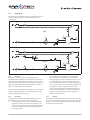
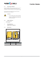
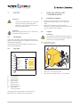
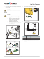
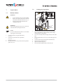
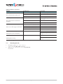
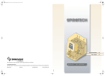
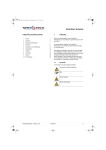
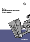
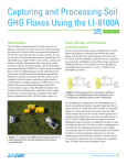
1
English
User Manual
PREFACE
TABLE OF CONTENT
/i
1
Preface
21
2
Introduction
22
3
Technical specifications
24
4
Safety
26
5
Installation and commissioning
26
6
Use
30
7
Failures
32
8
Maintenance
35
9
Guarantee
37
10
CE statement
37
All rights reserved. No part of this manual may be duplicated
and/or made public through the Internet, by means of printing,
photocopying, microfilm or in any other way without prior
written permission from Spirotech bv.
This manual has been composed with the utmost care. Should,
however, this manual contain any inaccuracies, Spirotech bv
cannot be held responsible for this.
This user manual deals with the installation, commissioning and
operation of the SpiroVent Superior types S4A and S4A-R.
Always carefully read the instructions before installation,
commissioning and operation. Keep the instructions for future
reference.
1.1
Symbols
Throughout the instructions the following symbols are used:
Warning or important note
Advice
Risk of electric shock
Risk of burning
User Manual - version 1.1
English
21
2
INTRODUCTION
2.1
Overview of the unit
A
B
C
D
E
F
R
S
Q
T
P
U
O
V
E
G
H
I
N
J
M
K
L
Superior S4A-R
A
B
C
D
E
F
G
H
I
J
K
L
M
N
22
Deaeration vessel
Automatic air vent
SmartSwitch
Inlet line
Solenoid valve
Outlet line
Screws
Valve behind pressure gauge
Pressure gauge
Pressure switch
Float switch (type S4A-R)
Drain connection
Pump
Pressure sensor (type S4A-R)
O
P
Q
R
S
T
U
V
English
Control unit
Filter
Cover
Aeration nipple
Refill connection (type S4A-R)
Float valve (type S4A-R)
Overflow (type S4A-R)
Refill reservoir (type S4A-R)
User Manual - version 1.1
2.2
Operation
The figure below schematically shows the operation of the unit.
The letter indications comply with the main figure on the
previous page.
D
P
C
PS
E
B
S4A
J
PS
R
M
PI
I
A
F
M
D
H
L
P
C
PS
K
S
LS
T
E
B
V
S4A-R
E
J
PS
N
R
M
PI
I
PT
A
F
M
2.2.1
General
The Superior is a fully automatic vacuum degasser for
installations filled with fluid. The fluid contains dissolved and
undissolved gases. The function of the unit is to remove these
gases from the installation until the concentration of undissolved
gases has reached an absolute minimum. Problems caused by
gases in the installation are thus eliminated.
2
Type S4A-R has an integrated refill automat. The refill automat
maintains continuous pressure in the installation. For this the
unit adds degassed fluid, if necessary.
2.2.2
Degassing
The unit starts up daily with the degassing process at a time
indicated by the user. The process knows two phases:
1
The rinsing phase: The fluid flows from the installation
through the solenoid valve (E) into the vessel (A). The
pump (M) continuously pumps the (degassed) fluid from
the vessel into the installation. Here the degassed fluid
absorbs gases again.
User Manual - version 1.1
H
L
The vacuum phase: The solenoid valve (E) regularly
closes, starting the vacuum phase. The continuously
running pump (M) provides underpressure in the vessel
(A). The underpressure causes the release of the gases
dissolved in the fluid, which are collected at the top of the
vessel. The solenoid valve (E) opens again, starting a new
rinsing phase. The gases collected in the vessel are
removed from the installation through the automatic air
vent (B). The SmartSwitch (C) ensures that degassing is
stopped as soon as the amount of dissolved gases has
reached the minimum level.
2.2.3
(Re)fill
Type S4A-R continuously checks the system pressure. The refill
process starts and stops automatically at the set values. Filling of
the system can also be started by an external signal overruling
the internal control of refilling.
English
23
2.3
Operating conditions
The unit is suitable for use in systems filled with clean water or
mixtures of water with a maximum of 50% glycol. Use in
combination with other fluids may result in irreparable damage.
The unit should be used within the limits of the technical
specifications as given in chapter 3.
WARNING
•
•
2.4
•
•
In case of doubt, always contact the supplier.
In case of a contaminated system fluid, a dirt
separator is to be installed in the main return
line of the installation.
Scope of delivery
1x SpiroVent Superior
1x User manual
TECHNICAL
SPECIFICATIONS
3.1
Dimensions
490
3
340
340
/i
Height [mm]
Width [mm]
Depth [mm]
490
340
340
24
English
User Manual - version 1.1
3.2
General specifications
/i
S4A
S4A-R
Max. system volume
25
m3
25 m3
Empty weight
15 kg
16 kg
Volume of degassing vessel
2l
2l
Inlet connection
Swivel G½” Bi
Swivel G½” Bi
Outlet connection
Swivel G½” Bi
Swivel G½” Bi
Noise level
52 dB(A)
52 dB(A)
Refill connection
n/a
Swivel G¾” Inside
Overflow connection
n/a
G1” Bu
S4A
S4A-R
230 V ± 10% / 50 Hz
230 V ± 10% / 50 Hz
Absorbed power
100 W
100 W
Nominal power consumption
0.5 A
0.5 A
Protection
3.15 A(T)
3.15 A(T)
Protection class
IP X4D
IP X4D
Max. load of potential-free contact (unit failure)
24 V / 1 A
24 V / 1 A
External refill signal (supplied voltage)
n/a
5 Vdc
S4A
S4A-R
1 - 4.5 bar
1 - 4.5 bar
Ambient temperature
0 - 40 °C
0 - 40 °C
Maximum pressure
10 bar
10 bar
Refill flow
n/a
50 l/hr
System fluid temperature
0 - 90 °C.
0 - 90 °C
Refill pressure
n/a
min. 0.5 bar
Refill fluid temperature
n/a
0 -30 °C
3.3
Electrical specifications
/i
Supply
voltage1)
1) 60 Hz on request
3.4
Other specifications
/i
System
pressure1)
(with closed valve behind pressure gauge)
1) 1.5 - 4.5 bar at 60 Hz
3.5
Building Management System (BMS)
The unit has been provided with one auxiliary contact for
communication with a BMS.
/i
Signal
S4A
S4A-R
Unit failure
Potential-free
Potential-free
User Manual - version 1.1
3.6
External refill control
If an external device controls the refill, feed in a cable and
connect this to connector J8. The control will sense an external
(potential free) contact as signal to start filling untill the contact
is released again. This can also be regulated indirectly with
BMS.
English
25
4
SAFETY
WARNING
•
•
Installation and maintenance of the unit should
only be carried out by qualified personnel.
Remove the voltage and pressure from the unit
before starting the activities.
WARNING
There are hot parts below the cover. Let the unit cool
down before starting the activities.
4.1
5
INSTALLATION AND
COMMISSIONING
5.1
Installation conditions
•
•
•
5.2
4.2
Unpack
WARNING
Do not hoist this equipment after the packaging has
been removed. The use of hoisting belts, chains and
hooks may cause irreparable damage.
CE marking
The unit has a CE marking. This means that the unit has been
designed, constructed and tested in compliance with the current
safety and health regulations.
Provided that the user manual is adhered to, the unit can be
safely used and maintained.
Install the unit on a frost-free, well-ventilated place.
Electrically connect the unit to a 230 V / 50 -60 Hz
socket.
Make sure the expansion system has the proper
dimensions. The water displacement in the unit can cause
pressure variations in the installation.
The unit is supplied in a box.
1.
Remove the packaging.
A
B
Type plate
A
B
C
D
E
SPIROVENT SUPERIOR
Article-No.:
Type:
Power input:
Voltage / Frequency:
IP class:
Pressure PS:
Temperature TS:
F
Serial no.:
Year of manufacture:
G
Spirotech bv - The Netherlands
H
I
A
B
C
D
E
F
G
H
I
A
Weight:
2.
3.
4.
Loosen the screws (A).
Remove the cover (B) from the unit.
Move the unit to the place where it is to be installed.
Article number
Type of the unit
Absorbed power
Supply voltage
Protection class
System pressure
System temperature
Serial number
Year of construction
The type plate has been applied on the inside of the unit.
Remove the cover to read the data on the type plate.
26
English
User Manual - version 1.1
5.3
Installation and mounting
5.3.2
CAUTION
Mechanical
•
•
Install the unit in accordance with the local
guidelines and rules.
Install the unit as bypass on the main
transport line of the installation.
Installation
> 500mm
A
B
NOTE
•
•
•
Preferably install the unit at the point in the
installation with the lowest temperature. Here
the most dissolved gases are found in the
fluid.
Make sure when installing that the operating
panel is always easily accessible.
Make sure that the you maintain a
minimal distance for service and repair
as indicated in the drawing below.
A
B
1.
•
2.
10cm
•
Make two branch lines ½” (A) on the side of the main
transport line. The distance between them should be at
least 500 mm.
Insert a valve (B) in each branch. With this the unit can be
depressurised.
CAUTION
Make sure that the valves are opened before putting
the unit into operation.
10cm
The area at the right of the unit at the
location of the "hole"S4" must be kept
free and uncovered at all times for means
of ventilation.
G
5.3.1
Mounting
B
A
E
A Ø8
C
F
D
NOTE
As seen from the direction of the volume flow, the
first branch is the inlet into the unit.
3.
4.
•
•
Wall mounting: Mount the unit to a flat, closed wall using
the holes (A). Make sure that the mounting can carry the
filled unit (empty weight +2 kg).
Floor mounting: Place the unit on a flat surface, against a
flat, closed wall.
User Manual - version 1.1
Connect the line (B) to the flexible outlet line (C).
Connect the line (A) to the flexible inlet line (D).
For type S4A-R:
1.
Insert a cut-off valve (E) in the supply line of the refill
fluid.
2.
Connect the supply line to the refill connection (F) of the
unit.
English
27
3.
Connect the overflow (G) to a drainpipe connected to the
sewage system.
2.
Insert the wires as indicated in the connector.
CAUTION
Make sure that the lines leave the unit at the rear.
Electrical
CAUTION
•
Preferably use a wall socket for the power
supply to the unit. This should always be
accessible.
Mount an all-pole main switch (contact
opening >= 3mm) if the unit is directly
connected to the power supply.
Use supply cables with the correct
dimensions.
Always replace a defect fuse by a fuse of the
same value. See § 3.3.
•
•
•
4
3.
Insert the connector.
J8
A
J9
J10
L N PE
4
3 2 1
J10
/i
1.
Feed a 3-core supply cable through swivel (A) and
connect this to connector J10.
1
7 mm
T >70°C
connector
contact
connection
J9
1 and 2
Failure
J8
1 and 2
External refill
4.
2
If a BMS is used, connect a BMS cable to connector J8
and/or J9.
L
N
PE
3
28
English
User Manual - version 1.1
5.4
Commissioning
5.4.1
Preparation
Follow the procedures given below for entering the required
parameters.
CAUTION
E
C
•
The start-up routine starts automatically
when the unit is switched on for the first
time.
Press EXIT to go back one step in the menu
while programming.
D
•
A
1.
2.
3.
B
Open valve (A) behind the pressure gauge (B)
Open the valves (C and D) in the inlet and outlet lines.
Open the valve (E) in the refill line.
5.4.2
Set date en time
1.
Press ON/OFF.
2.
Select a language using S and T. Press ENTER.
3.
Set the date using S and T. Press ENTER.
4.
Set the day using S and T. Press ENTER.
5.
Set the time using S and T. Press ENTER.
Filling the unit
1.
Press ENTER. The unit starts filling.
2.
Wait for 50 seconds until Initial filling in
process disappears.
3.
Press EXIT two times.
Start up
NOTE
The green LED "OK" indicates that the unit is ready
for use. The degassing starts by default daily at
08:00 hours.
A
B
C
Check function
D
A
B
C
D
E
F
G
H
I
I
D
H
E
G
F
On/off
Display
Status report in operation / OK
Up
Confirm / Enter
Menu
Down
Cancel / Exit
Status report failure
E
1.
2.
3.
4.
User Manual - version 1.1
A
English
D
B
Manually start the unit, see § 5.4.2.
Check the indication of the pressure gauge (B). This
should alternately display overpressure and underpressure.
Close the valve (A) behind the pressure gauge.
Place cover (C) back onto the unit. Slide the bottom of the
cover in the recess (E).
29
5.
Fasten the cover with the screws (D).
5.5.2
NOTE
The SmartSwitch will automatically turn off the
unit when the concentration of dissolved gases has
reached the minimum level.
NOTE
If manually switched off, the process must be
manually switched on again.
1.
5.5
Install and operate
5.5.1
Install
Manual operation
2.
Set the user parameters
1.
Press MENU. Select Settings using S and T. Press
ENTER.
2.
Select the parameter to be changed using S and T. Press
ENTER.
3.
Change the setting using S and T. Press ENTER.
4.
Repeat steps 2 and 3, if necessary.
5.
Repeatedly press EXIT to return to the status report.
Press MENU. Select User menu > Manual
operation using S and T. Press ENTER.
Select Manual operation start or Manual
operation stop using S and T. Press ENTER.
5.5.3
Switch on again
Follow the procedure described below after the unit has been
switched off.
1.
Press ON/OFF.
2.
Press ENTER two times. The unit starts filling.
3.
Wait for 50 seconds until Initial filling in
process disappears.
4.
Press EXIT two times.
/i
NOTE
The green LED "OK" indicates that the unit is ready
for use.
Parameter
Description
Language
Language for the display texts.
Date
The current date.
Weekday
The current weekday.
Time
The current time.
Auto start
Time for starting the degassing process.
Block.time, day
Time for stopping the degassing
process.
Block.time week
Days of the week on which the unit is
not working.
Selected days are marked with an *.
After having changed this parameter,
select Store using S or T. Press
ENTER.
Block.time year 1
Period per year during which the unit is
not working.
Block.time year 2 3
See Block.time year 1.
Max. Psystem *)
Pressure at which the unit stops.
Psystem
desired*)
Pressure at which the refilling stops.
Refill on
at*)
Pressure at which the refilling starts.
Refill alarm
after*)
Max. refill freq.*)
*) Applies to type S4A-R
Continuous refilling time (0 - 255 min.;
0 = switched off).
Maximum number of times per day that
refilling is allowed
(0 - 10 times; 0 = switched off).
5.5.4
Reading the memory
During operation the following data are stored in the memory:
•
Accumulative running hours
•
Degassing history
•
Fault history
•
Refill history (only on type S4A-R).
The memory can be read in the following way:
1.
Press MENU. Select User menu > History using S
and T. Press ENTER.
2.
Select Fault history or Action history using
S and T. Press ENTER.
3.
Select an item using S and T. Press ENTER.
4.
Repeatedly press EXIT to return to the status report.
5.5.5
Reading data
The following general data have been stored in the memory of
the unit:
•
Unit type
•
Software version
•
Installation date.
The general data can be read in the following way:
1.
Press MENU. Select User menu > General data
using S and T. Press ENTER.
2.
Select an item using S and T. Press ENTER.
3.
Repeatedly press EXIT to return to the status report.
6
USE
6.1
General
•
30
English
The display lighting automatically dims after no key has
been pressed for 5 minutes. Press a key to activate the
lighting.
User Manual - version 1.1
•
While stopping the process a stop procedure is started,
making sure that the unit stops in a safe situation
(overpressure).
When the pump has not run for 96 hours, an automatic
pump test is run at the first next Auto start.
Press ON/OFF to switch off the unit. Press ON/OFF again to
switch on the unit again.
•
•
6.2
•
•
At low fluid temperatures condensation may occur at
certain parts. The condensation is drained through the
openings in the frame.
For type S4A-R:
The refill flow is about 50 litres per hour.
Status reports
/i
Report
Description
LED indication
Auto pump test
The unit runs a pump test.
Green
End of degassing
The stop procedure is in process.
Green
Degassing
The degassing process is in process.
Green
Process stopped
The unit has been stopped manually.
None
Standby
The unit is waiting for a starting signal.
Green
Failure
The unit has stopped because of a failure. Remedy the failure before
resetting the unit, see § 7.4.
Red
Refill (only on S4A-R)
The unit is refilling fluid.
Green
End of refilling
U s e r M a n u a l - v e r s io n 1 . 1
English
31
7
FAILURES
7.1
Remedy failures
7.2
C
WARNING
•
•
•
F
WARNING
There are hot parts below the cover. Let the unit
cool down before starting the activities.
1.
2.
3.
4.
32
Localise the failure using the failure table,
see § 7.3.
If necessary, put the unit out of operation,
see § 7.2.
Remedy the failure.
Reset the unit, see § 7.4 or put the unit into operation
again, see § 5.5.3.
B
A
In case of failure always warn the installer.
Remove the voltage and pressure from the
unit before starting the activities see § 7.2.
Pressing ON/OFF does not remove the
voltage from the unit.
NOTE
In case of a failure the red LED is lit. The failure
report appears in the display.
Putting out of operation
D
E
1.
2.
3.
4.
5.
6.
7.
English
Take the plug out of the wall socket and switch off the
main switch. Make sure that switching on the voltage
unintentionally is not possible.
Close the valves (B) in the inlet pipe and (A) in the outlet
pipe.
Close, if applicable, the valve (C) in the refill supply line
as well.
Connect a drain line (E) to the drain connection (D).
Open the drain connection (D).
Open the aeration nipple (F)
Drain the unit through the drain connection (D).
User Manual - version 1.1
7.3
The letter indications comply with the main figure in § 2.1. An
overview of the replacement parts has been included in § 8.2.
Failure table
General
Problem
Possible cause
Correction
Err 5 Inlet flow
The solenoid valve (E) in the inlet line
does not open.
Replace (a part of) the solenoid valve.
A valve in the inlet line is closed.
Open the valve.
The filter (P) is clogged.
Clean the filter.
The pressure switch (J) is defect.
Replace the pressure switch.
The solenoid valve (E) does not close
(inlet pipe).
Replace (a part of) the solenoid valve.
The valve in the outlet line is closed.
Open the valve.
The outlet line has been obstructed.
Remove the obstruction.
The pump (M) does not run.
Check the pump.
The unit sucks in air during the vacuum
phase.
Replace the automatic air vent.
The pressure switch (J) is defect.
Replace the pressure switch.
The content of dissolved gases has not
reached the minimum yet.
Check whether there is a possibility of
gases entering the installation.
The SmartSwitch (C) is defect.
Replace the SmartSwitch.
The SmartSwitch (C) is defect.
Check whether gas is released through the
valve. Replace the SmartSwitch if the
valve does not work.
The automatic air vent (B) is defect.
Replace the automatic air vent.
The flow in the inlet line has been
blocked.
Err 6 Flow
The flow in the outlet line has been
blocked .
The unit runs continuously and does not
switch off automatically.
The SmartSwitch does not seem to work.
The unit runs maximally 10 min. per
degassing period. Gases remain in the
installation.
The SmartSwitch does not seem to work.
User Manual - version 1.1
English
33
Applies specifially to type S4A-R
Problem
Possible cause
Correction
Err 1 Psystem too low
A failure in the installation.
Provide a system pressure of > 1 bar.
There is a leak in the installation.
Repair the leak.
The pressure sensor (N) is defect.
Replace the pressure sensor.
Err 2 Psystem too high
A failure in the installation.
Provide a system pressure that is below
the set value.
The system pressure exceeds the set
maximum.
The set value is too low.
Increase the set value.
The pressure sensor (N) is defect.
Replace the pressure sensor.
A valve in the refill line is (partly) closed.
Open the valve.
The refill line has been obstructed.
Remove the obstruction.
The float switch (K) is defective.
Replace the float switch.
The float valve (T) is defective
Replace the float valve
There is a leak in the installation.
Repair the leak.
The system pressure is below 1 bar.
Err 10 Refill flow too low
There is no or little supply of refill fluid1).
Err 13 Refill freq. too high
Check the setting Max. refill
freq.
Refilling takes place too frequently.
Err 14 Refill too long
There is a leak in the installation.
Repair the leak.
Check the setting Alarm refill
after:
Refilling takes too long.
1) The refilling function remains active (type S4A-R only).
7.4
1.
2.
34
Resetting the unit
Press MENU. Select User menu > Manual
operation using S and T. Press ENTER.
Select Manual operation reset using S and T.
Press ENTER.
English
User Manual - version 1.1
8
MAINTENANCE
8.1
Periodic maintenance
1.
2.
Inspect and clean the filter (P) regularly.
Replace the automatic air vent (B) every two years.
8.2
Replacement parts
The letter indications comply with the main figure in § 2.1.
Article number
Letter
/i
Description
R16.181
M
Pump type MK309XE 50 Hz
R18.781
M
Pump type MK309XE 60 Hz
R18.782
M
Capacitor 50/60Hz
R18.748
Q
Cover
16.342
E
Solenoid valve (excluding coil)
16.343
E
Coil for solenoid valve
16.344
I
Pressure gauge
16.345
B
Automatic air vent
16.346
J
Pressure switch
R18.704
O
Control unit (S4A)
R18.705
O
Control unit (S4A-R)
16.349
C
SmartSwitch
R18.703
N
Pressure sensor (S4A-R)
16.355
P
Filter interior
16.351
T
Float valve
16.352
K
Float switch
User Manual - version 1.1
English
35
8.3
Maintenance card
/i
Type:
Serial number:
Installation date:
Installed by firm:
Installed by technician:
Inspection date:
Technician:
Initials:
Technician:
Initials:
Technician:
Initials:
Technician:
Initials:
Technician:
Initials:
Technician:
Initials:
Nature of the maintenance:
Inspection date:
Nature of the maintenance:
Inspection date:
Nature of the maintenance:
Inspection date:
Nature of the maintenance:
Inspection date:
Nature of the maintenance:
Inspection date:
Nature of the maintenance:
36
English
User Manual - version 1.1
9
GUARANTEE
•
9.1
Terms of guarantee
•
•
The guarantee lapses in cases of faulty installation,
incompetent use and/or non-authorised personnel trying to
make repairs.
Consequential damage is not covered by the guarantee.
The guarantee for Spirotech products is valid until 2 years
following the purchasing date.
10
CE STATEMENT
10.1
Declaration of conformity
/i
According to EN-ISO/IEC 17050:2004
Manufacturer
:Spirotech bv
Adress
:Churchilllaan 52
5705 BK Helmond
The Netherlands
Products
:SpiroVent Superior S4A / S4A-R
/i
We declare entirely on our own responsibility that these products comply with the following standards:
EN 12100-1, EN 12100-2, EN 809, EN 60204-1, EN60335-1,
EN 61000-3-2, EN 61000-3-3, EN 55014-1, EN 55014-2, EN 61000-6-1, EN 61000-6-2, EN 61000-6-3 and
EN 61000-6-4.
in accordance with the stipulations of:
-
Machine Directive 2006/42/EC
Low Voltage Directive 2006/95/EC
EMC Directive 2004/108/EC
Helmond, validated 1 July 2010,
Dr. D. Scholten
Managing Director
User Manual - version 1.1
English
37