1
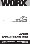
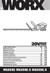
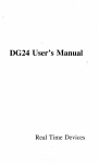
INSTRUCTION MANUAL
CAR.ON MODEL 2050
CONSTANT TEMPERATURE BATH
HEATED AND REFRIGERATED
Revised 5/15/00, Rev B
2050 Users ManuaLdoc
SPECIFICATIONS
Standard Features
Temperature Range
-15°C to 90°C
Temperature Control
±0.1 °C
Temperature Controller
Watlow 935 (digital display)
Cooling Capacity
1050 BTU/Hr or 300 W @ 20°C
External Pumping
12LPMat0'head
Work Area Dimensions
8"W x 2"F-B x 6.5"D
External Dimensions
13.5"Wxl3.5"F-Bxl4"H
Heater
750W
Fittings
Quick disconnects
Safeties
Over temperature shutoff (factory set)
Reservoir Capacity
1.4 Gallons
Reservoir Lid
Stainless Steel
Batb. Material
Stainless Steel
Shipping weight
49 lbs
Cabinet Material
Stainless Steel, powder coated metal
Feet
6 vinyl
Warranty
12 months parts & labor
2050B115V
2050W115V
2050W230V
now
now
170W
115V,60Hz, 10A
115V,60Hz, 10A
230V, 50/60Hz, 5A
Audio & visual
Audio & visual
Lpw fluid level alarm
...
Audio & visual .
Audio & visual
Approvals
-
Features
Compressor size
Power
Over temperature alarm
Revised 5/15/00, rev B
-
2050 Users ManuaLdoc
CE Marked
INSTALLATION
Unpacking: This CARON product has been completely tested, cjeaned and carefully packed for
shipment. Please be careful when unpacking.
Please examine the bath carefully. Should any damage be found, notify the delivering carrier
immediately. Report any shortages to the CARON Service Department at 800-648-3042.
Locating the 2050 Series Bath: The bath must be located in a dry, clean and level area. It is also very
important that air is allowed to move from the top of the bath through the unit and out the back freely.
This will help provide years of trouble-free operation.
Power: PLEASE READ CAREFULLY! For personal safety this bath must be properly grounded. The
power cord of this bath is equipped with a grounded plug which mates with a standard grounded wall
outlet.
Revised 5/15/00, rev B
2050 Users ManuaLdoc
SYSTEM
WARNING: DO NOT OPERATE THIS BATH WITHOUT SUFFICIENT LIQUID IN THE
RESERVOIR OR SEVERE DAMAGE COULD OCCUR.
Please read operating instructions before 6perating the bath.
Note: Do not overfill bath; please allow for the addition of product
1. Power Switch:
This switch controls power to the CARON Model 2050 Bath.
2. Refrigeration Switch:
When in the "on" position, a built-in refrigeration unit will also be energized. Do not operate this
bath before reading operation instructions on pg. 5 of this manual.
3. High Temperature and Low Liquid Level Safety Sensors:
A. (2050B Models only) A temperature sensor located on the heater sheath and independent
control circuit act as an over-temperature safety shut-off. Strategically located, this sensor may
also trip if the fluid is low. However, it will not detect an empty or low reservoir upon startup!
B. (2050W Models only) An over-temperature safety thermostat protects against an overtemperature condition. This not only removes power to the heaters but also signals the overtemperature condition to the user via an audible sound and red warning light A float switch
trips when the fluid level is not high enough. It also shuts off power to the heater, sounds an
alarm and illuminates a red warning light.
4. Main Temperature Control:
The CARON Series 2050 Bath has been equipped with an extremely sensitive and accurate temperature
control. This control is sensitive to ± 0.1 °C. A 1/32 DIN panel-mounted, digital indicating temperature
controller is used. It uses a 100Q RTD immersion probe to sense process fluid temperature. The
controller is microprocessor based with a PID control algorithm that drives a switched DC output in a
•pulse-width-modulated fashion. A second output is set as a ±5°C tracking alarm about the process set
point. Outputs for this alarm are both an indicator light on the controller and a switched DC voltage that
•can be used to drive an optional remote alarm relay.
Revised 5/15/00, rev B
2050 Users ManuaLdoc
5. Heat Pilot Lamp:
When the main temperature control is injecting heat into the bath for control purposes, the controller
signals a light for output 1 of the controller.
6. External Circulation:
Provided by an independent full flow stainless steel pump. This p'ump will deliver in excess of 11 LPM
while adequately maintaining internal circulation.
Revised 5/15/00, rev B
2050 Users ManuaLdoc
OPERATION
WARNING: DO NOT OPERATE THIS BATH WITHOUT ADEQUATE LIQUID
OR SEVERE DAMAGE COULD OCCUR.
WARNING: DO NOT OVERFILL THE BATH - damage to the bath could occur!
ALLOW FOR THE ADDITION OF PRODUCT!
1. Filling the bath reservoir
Fill the bath with an appropriate fluid. 2050W models should be filled until the low liquid level alarm
shuts off.
Water is recommended as the fluid medium for applications requiring temperatures above
10°C. To help keep the bath clean, add 5 milliliters of bleach or algaecide to the bath before starting.
Methanol or a solution of antifreeze and water are recommended for temperatures below 10°C. Follow
the directions on the antifreeze container for the proper mix.
NOTE: Observe liquid level of bath to safeguard against overflow: damage to the unit could occur!
NOTE: Operation of the unit in temperature ranges at or near 0°C may cause the hygroscopic antifreeze or
ethylene Glycol to attract water into the reservoir. In areas of high* ambient humidity this could cause the
reservoir fluid to overflow.
Control System
The control system is comprised of a Watlow 935 1/32 DIN Controller. The display panel consists of a
power and refrigeration switch. 2050W models also have a low liquid level indicator light and overtemperature indicator light.
2. Emptying the bath
To empty the bath, simply remove the 1/8" plug located on the lower left side of the bath.
3. Connecting Power:
Revised 5/15/00, rev B
2050 Users Manual-doc
t
Check all switches to be sure they are in the "off" position. Plug the line cord into a suitable outlet (verify
correct voltage).
4. Setting Controls:
Set main control to the desired operating temperature. Turn on power switch. Turn on the refrigeration
switch (REF) for operating at temperatures below 60°C. Allow the reservoir to stabilize 1 hour before
adjusting the operating temperature. The safety control has been mounted behind the control panel and
calibrated at 90°C. For re-calibration of the controller please see Field Calibration Section, pg. 9.
Note: External circulation begins immediately when power is Jturned ON!
5. Making External Circulation Connections:
With the unit turned off, connect your external instrument to the male quick disconnects. Insert the male
quick disconnects into the female quick disconnects mounted on the bath's reservoir. When quick
disconnects are in place and the unit is turned on, the external circulation pump will function and
externally pump liquid at the outlet side of the pump. Be certain to connect the circulator's male
quick-disconnects to your instrument's inlet and outlet circulation lines before turning the unit on.
Revised 5/15/00, rev B
2050 Users ManuaLdoc
CONTROLLER PARAMETERS
Operations Menu
Set
Aut =
ALO =
Ahl =
CnF9 =
5
no
Setpoint
Auto-tune
Alarm Low
Alarm High
Configuration Menu
PED Menu
Pbc =
Ctc =
It
dE
CAL =
7.5
1.7
2.0
.75
0
Proportional Band 1
Cycle Time Cool 1
Integral Function
Derivative Function
Calibration Offset
20°C
no
-5
Configuration Menu
In
Rtd
C F =
°C
rL
-17.0
rh
90.0
Otl
=
Heat
Ot2 =
ALM
dISP =
Ac
ALtY =
d£nc
AhYS =
5
LAt =
no
SDL =
no
FAIL =
0
SLOC =
no
tA9 =
(Blank)
Input Type
Celsius/Fahrenheit
Input Range Low
Input Range High
Output 1 Function
Output 2 Function
Display Default
Alarm Type
Alarm Hysteresis
Alarm Latch
Alarm Silencing
Failure Mode
Set Point Lock
Lockout Tag
ROUTINE MAINTENANCE
Cleaning the bath: The bath interior should be cleaned with a general purpose laboratory disinfectant such
as Cole-Parmer #G-08796-00 lab algaecide.
Cleaning the refrigeration unit: Twice a year the dirt that has built up on the outside of the compressor
and fan should be vacuumed or blown off. This permits a free flow of air around the refrigeration unit and
allows it to operate more efficiently. In areas where there is a high particulate content in the air, the
refrigeration unit should be cleaned more often.
Revised 5/15/00, rev B
2050 Users ManuaLdoc
TROUBLESHOOTING
Problem: Bath power will not energize
Possible Causes:
1. Line cord not plugged in
2. No current at receptacle
3. Defective line cord
4. Defective power switch
5. Built-in fuse defective
Problem: Bath will not cool
Possible Causes:
1. Control set incorrectly
2. Thermal overload on compressor
3. Defective starting relay on compressor
4. Defective refrigeration circuit
5. No circulation in bath
6. Refrigeration Switch not on
Problem: Bath will not heat
Possible Causes:
1. Control set incorrectly
2. Defective temperature control
3. Heater burned out
4. Over temperature alarms
5. Low liquid level
Problem: Over-temperature safety energized
Possible Causes:
1. Incorrectly set
2. Liquid temperature too high
3. Defective control
4. Low fluid level (2050B model only)
Problem: Erratic Control
Possible Causes:
1. Inadequate circulation
2. Bad sensor
3. Defective control
4. Heater defective
5. Bath going in and ourt of alarm condition
Problem: Low Liquid Level Energized (2050W models only)
Possible Causes:
1. Low liquid level
2 Defective control
Problem: Alarm Energized (2050W models only)
Possible Cause:
1. Overtemperaure situaion
2. Low liquid level
Revised 5/15/00, rev B
2050 Users ManuaLdoc
TEMPERATURE CONTROL FIELD CALIBRATION
Note: This CARON Bath has been completely calibrated and tested in every aspect of its
capabilities. Please call the CARON Service Department should any problem or question develop
regarding this product's operation.
Go to the PID Menu on your WATLOW 935 User's Manual
1. Go first to the Operations Menu by pressing up / \
and down
arrow keys simultaneously for three seconds.
2. Scroll through the Operations Menu with up and down arrow keys until you see the
PJDJ prompt.
3. While pressing SET to display NO choose YES with the up and down arrow keys.
4. Release the SET key to see the first PID prompt.
5. Using the down arrow, scroll through the PID menu until you see the CAL prompt.
6. To view and change the calibration setting, push and hold in the SET button. Use the
up or down arrows to acheive the desired calibration.
7. To exit simultaneously, press and hold up and down arrow keys for three seconds or
refer to pg 14 of your WATLOW 935 User's Manual.
8. Refer to your WATLOW 935 user Manual for additional assistance or call CARON
Service at 740-373-6809.
Revised 5/15/00, rev B
2050 Users ManuaLdoc
10
D
B
: 8YS otsavnat
OATB
A
08-30-09
05-12-40
E30V
1PH
I_ 1
„,„
5A
S2LJL
MJWL RELEASE
R S M O O C D WRES
RSUOVCD CAP Z *
/OOGD I I X . JT MOOGL
W/A
2090Wa22Q_9
20S0FAUO-
MAIN PdVER
L 2
NOTES
!.
LAST CONDUCTOR USED I S 21
RFI POWER RLTER INSTALLED
ON JT MODEL ONLY
VATLDV 935
750 V
IMMERSION
HEATER
ALARM
2
DVERTEMP
THERMOSTAT
OVER TEMP
LEVEL SWITCH
LOW LEVEL
t——^•NAJ' ' ""
iRr——'
REF-SVITCH
COMPRESSOR
CONDENSER FAN
,
86
PUMP MOTOR
8 A
CAR@N
"Tour Thermal Solution Team
P.O. Box 715. U o t t t a . OH 4S7S0
PN 740373^909
FAX 74037.13700
B
MOOEL#! 2O50W
SCA1& t : 1
oca
SHEET SEE:
C
CHKU at:
DATE:
SHEET : 1 OF 1
TDLffiANCS UNLESS OIHERWEE NOTED:
APP:
UATERIAU N/A
OAIE
X. ± .1
OfWWN 3ft BJUYES
RUSH: N/A
A
PART ft205CW«250
a 2oso zx>i WATLOW U S EIECTWCL SOHEMAHC
X ' ± .05
X ± \'
X ± J '
XC ± J1
D
A
B
ia t
115V
n«e
an
(K-M-CO
9»
1 PH
LI
NOTES
at at-.
D
Btt DESOBPTOfe
WCJW. RELEASE
ECN i
N/A
10 A
L
2
1. LAST CONDUCTOR USD) IS 19
4
8
OVER-TEMP
CONTROLLER
CAR@N
T o u r Tharmal Solution Team*
PO. 9en 719. MarMta. ON 46790
PH T4O_573.8OO»
FAX 740 J 7 + J 7 9 0
20503
DRAWN Bf: B, OOTTEPER
CHKTJ: at-.
APP:
MATBWAb
FINISH: W/A
B
PACT £33508.115
1ITU5 2 0 9 0 a*SIC H 5 v WA1U3W 93S OECIRICAI. SCHEMATIC
N/A
QATE: as-as-oo
QATE:
OATC:
SOLE t : 1
SHEET SEE
C
SHEET : 1 OF 1
TOEfWCES UNLESS OIHEWKE NOTEft
X. ± .1
X ± r
X
t JB
XC i
Jtt
JC ± JS *
CARON PROCIUCTS
Limited Warranty
CARON PRODUCTS & SERVICES, INC. (herein after CARON) hereby warrants that equipment
manufactured by CARON is free from defects in materials and workmanship when the equipment is used
under normal operating conditions in accordance with the instructions provided by CARON, as follows:
COVERED:
- Parts and labor for a period of one (1) year from date of delivery, expiring on \rl~ \ ^ ~ ~ O |
Any part found defective will be either repaired or replaced at CARON's discretion, free of charge by
CARON in Marietta, OH. Parts that are replaced will become the property of CARON.
- This service includes diagnosis and correction of individual CARON product malfunctions, failures and ma
consist of temporary procedures to be followed by the customer while a permanent solution is sought.
- If CARON factory service personnel determine that the customer's unit must be returned to the factory,
CARON, at its sole discretion, could provide a loaner unit for the customer's use while the customer's unit is
being serviced. CARON would ship the loaner to the customer, and back, plus ship the customer's unit to
the factory and back. CARON will pay all ground shipping charges via UPS or other common carrier.
- CARON will have the right to inspect the equipment and determine the repairs or replacement parts
necessary. The customer will be notified within a reasonable time after inspection of any costs incurred thai
are not covered by this warranty prior to initiation of any such repairs.
NOT COVERED:
- Cost of express shipments; Federal Express, UPS next day air, UPS second day air or any other express
shipment charges.
,
- Any customer modification of this equipment or any repairs undertaken without the prior written consent o
CARON will render this limited warranty void.
- CARON is not responsible for consequential, incidental or special damages. In no event will CARON be
responsible for damages more than the price of the product.
- Repairs necessary because of the equipment being used under other than normal operating conditions o
for other than its intended use.
- Repairs or replacements of parts due to the customer's failure to follow normal maintenance instructions.
- Force Majeure or acts of God.
This writing is a final and complete integration of the agreement between CARON and the custome
CARON makes no other warranties, express or implied, of
merchantability, fitness for a particular purpose or otherwise, with respect to the goods sold undei
this agreement This warranty can not be altered unless CARON agrees to an alteration in writing.
Any changes or modifications to this limited warranty must be in writing and signed by both partie
No course of dealing, course of performance or trade usage, except as expressly stated herein, sh
be recognized to vary or modify this contract
THIS WARRANTY IS GOVERNED BY OHIO LAW
CARON PRODUCTS & SERVICES, INC. PRODUCTS LANE
Caron Warranty.doc
12/02/99
CE Compliant Product
Declaration of Conformity
C€99
Caron Products and Services, Inc.
P.O. Box 715
Marietta, OH 45750 USA
Declares that the following product:
Designation:
Model Number
Classification:
Rated Voltage:
Rated Frequency:
Rated Power Consumption:
Series 2050
2050W JT
Electrical equipment intended for residential, commercial
and light industrial environments.
220-240 ~ (ac)
50/60 Hz
5 amps
Meets the essential requirements of the following European Union Directive(s) using the
relevant section(s) of the normalized standards and related documents shown:
89/336/EEC Electromagnetic Compatibility Directive
EN 50082-1
1992
IEC 801-2
IEC 801-3
IEC 801 -4
1984
1984
1988
EN 55011
1998
EMC Generic immunity standard, Part 1: Light
industrial environment.
Electrostatic discharge
Radiated susceptibility
Electrical fast transients
Group 1, Class B Emissions Requirements for
Industrial, Scientific or Medical equipment.
73/23/EEC Low- Voltage Directive
EN 61010-1
1993
Safety requirements for electrical equipment for
measurement, control, and laboratory use.