1
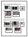
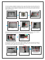
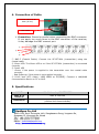
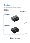
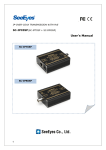
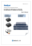
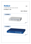
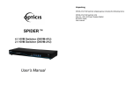
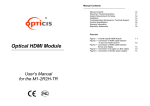
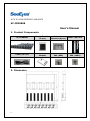
8 CH IP-LINK RECEIVER SUB-RACK
SC-IPR0808
User's Manual
1. Product Components
SC-IPR0808
Mount Bracket
(2 pcs)
Adapter’s
Bracket (8 pcs)
Multi Tap Cord
Cable (3C-2V)
Instruction
Manual
Round bolt
4X4 (8EA)
Round bolt
3X6 (16EA)
2. Dimension
0
3. How to assemble the SC-IPR0808 Sub-Rack
1) Fix the two pieces of mount bracket at each side of the sub-rack using the
4x4 round bolts as below.
4X4 round bolt
Sub-rack left/right side
Tighten the bolt as above.
The head of the bolt should
face up to inner side of the
rack.
Mount bracket
Fix the rack using the mount
bracket
2) Remove the left side cover of SC-IPR0801 (receiver) as below. Fix the SCIPR0801 at the front of the sub-rack using flat headed bolt to the same direction
indicated by the arrow. When tighten the receiver use the flat headed bolt of the
SC-IPR0801. Please be careful not to miss the 4 pieces of 3x8 flat headed bolt.
SC-IPR0801 (Receiver)
Fix the SC-IPR0801 receiver
into the sub-rack to the
arrow’s direction.
1
Remove the side cover.
Remove the flat
headed bolt (3X8)
and keep them
aside.
Tighten the receiver using the
flat headed bolts
3) Put the power adapter’s bracket at the rear side of the sub-rack and then fix
the bracket to the sub-rack using the small 3X6 round bolt. Put the two pieces of
power adapter at the adapter’s bracket and then fix the second bracket using the
same bolt as below.
Bracket for the power adapter
First, locate the rear side
brackets.
Round headed bolt
(3X6)
Put two power adapters
as indicated the above
arrow.
Fix the bracket.
Install the second bracket
and fix the adapter
4) Connect the 3 Pin terminal block with the harness cable of the power adapter
and then connect the terminal block to the receiver (SC-IPR0801).
+
5) Connect the power cord to the power adapter and then connect the plug of
the adapter to the multi tap cord located at the back side of the sub-rack. Finally,
tidy up the power cables using the cable ties.
Power cord of the power
adapter
Connect the power cord to the
adapter
Connect the power plug to
the multi tap cord.
2
4. Connection of Cable
Coaxial Cable for IP
data (3C-2V)
UTP Cable
※ Precaution: Please be careful when connecting the BNC connector.
If you apply too much force to the BNC connector of the receiver,
it may damage the BNC connect port.
①
②
③
④
① BNC-F (Coaxial Cable): Connect the SC-IPT0801 (transmitter) using the
coaxial cable.
② Green LED: The Green LED is on if the SC-IPT0801 (transmitter) is connected
correctly.
③ Power LED
- Green: if the power is supplied to the transmitter over the coaxial cable
correctly.
- Red flickering: if the power is not supplied correctly.
④ RJ-45 Jack (UTP cable): LAN/ WAN or PC(NVR). Connect a LAN/WAN
communication device or PC or NVR.
5. Specifications
MODEL
Max. # of
Receiver
Dimension
SeeEyes Co.,Ltd
3
8ch Sub-rack / SC-IPR0808
Max. 8 receivers
430(W) ⅹ 66(H) ⅹ 470(D) mm
(without the mount bracket)
#502~506, Sunil Technopia, 440, Sangdaewon-Dong, Jungwon-Gu,
Sungnam-Si, Gyeonggi-Do, Korea
TEL : +82-(0)31-777-3508
FAX : +82-(0)31-777-3512
EMAIL : [email protected]
http://www.sscctv.com/eng