1
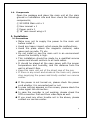
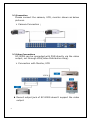
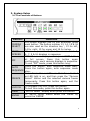
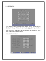
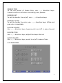
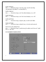
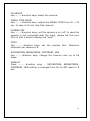
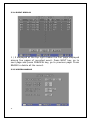
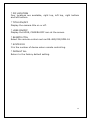
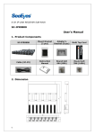
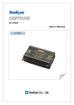
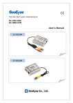
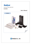
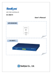
9 CHANNEL DIGITAL COLOR SPLITTER SC-90DS User's Manual SC-90DS Precaution and Safety Guidelines Please read this manual carefully and fully understand the portions of the installation and operation instructions prior to installing and using the product. Should you have any part of them not understandable or if you have any problem during your installation or in using it, please contact us. Reproduction of this instruction or any part thereof without permission is strictly prohibited. You must read the precautions required for safe operation prior to using it and operate it correctly. Please understand that the contents of this operating instruction may differ slightly due to functional improvement of a product and based on the specification chosen by the user. You can use this product easier and more conveniently if you use the function of the product only after reading this operating instruction carefully. CAUTION RISK OF ELECTRIC SHOCK DO NOT OPEN CAUTION : TO REDUCE THE RISK OF ELECTRIC SHOCK, DO NOT REMOVE COVER. NO USER SERVICEABLE PARTS INSIDE. REFER SERVICING TO QUALIFIED SERVICE PERSONNEL. The lightning flash with arrowhead symbol within an equilateral triangle, is intended to alert the user to the presence of uninsulated “dangerous voltage“ within the product‟s enclosure that may be of sufficient magnitude to constitute a risk of electric shock to persons. The exclamation point within an equilateral triangle is intended to alert the user to the presence of important operating and maintenance (servicing) instructions in the literature accompanying the product. ※ WARNING: To reduce the risk of fire or electric shock, do not expose this apparatus to rain or moisture. 1 1. Overview 1.1 Overview With this splitter monitor can display various quads, sequence, etc. video signal from the 9 number of video inputs at SC-90DS. It displays the name of channel, date and time as well as event such as loss. 1.2 Functions User- Friendly POP UP menu It is easy to access the MENU with the user friendly interface. Minimized button, LED display Easy to run through the minimized buttons at front panel. As LED shows the current working status of this equipment, it is convenient to run & see. Connect with 9pcs of cameras as well as real time display of 9 splits Auto Sequencer Auto sequence of full screen display is available as per setting. Date, time, channel & current status display with OSD Freeze It is available to see the stop frame each and all at the 9 splits mode. Loss alarm and event record In case of loss at video input, it display, alarm and record the event. 1:1 full screen display 1:1 scale full screen display is available as per the user‟s selection. Playback Connecting with VCR input playback the recorded video. Various Interface Various interface such as 9 ports of video inputs, monitor output, VCR inputs. As it has 75Ω BNC to connect DVR easily, no need the video distribution amplifier. Remarkable Feature With the optimal circuit and chip designing, it is very stable and able to apply the various applications. 2 RS-232/485 Remote control is available through RS-232/485 COM. Combining with our DVR controller, it is available to control & watch the eight sites with the real time. 1.3 Specifications Model No. Video Input Video Output Function Monitor Out Loop Thru Rec. Out Date / Time Camera Title Sequence Split OSD Loss Motion Detect Resolution Power Weight Dimension 3 SC- 90 DS 9 Channels of cameras & VCR BNC Type, Auto termination, 1.0Vp-p 75 Ω Yes Yes No Built-in RTC (accuracy : ±1 min./month) Y/M/D, H/M/S Max. 8 character (Eng, Num, *) display /CH, On / Off Set (Off ~ 30 Sec.) per channel Exclude the loss channel automatically 1/2/4/7/9 OSD position set OSD on/off Loss displays & buzzer & record the event No 500 TVL 100 ~ 240V, 50/60Hz, 16W 3.50 kgs 430 (W) x 44(H) x 350(D) 1.4. Components Open the package and place the main unit at the plain ground or installation site and then check the followings components; ① SC-90DS Main unit x 1 ② User manual x 1 ③ Power cord x 1 ④ 19” rack mount wing x 2 2. Installation 2.1 Precautions Make sure not to supply the power to the main unit before install it. Avoid any heavy impact, which cause the malfunctions. Avoid the place where the magnetic material, radio wave such as radio, TV, etc. Do not install or use the main unit in an environment where the humidity is high. This installation should be made by a qualified service person and should conform to all local codes. It should be placed at the open space with the proper temperature and humidity, and the distance from the wall is at least 15cm. Keep this main unit out of the direct rays of the sun. If there is any smell and smoke at the main unit, please stop supplying the power and kindly contact our service center. If the power is not turned on, please check the power cord whether it is connected well or not. In case nothing appears on the screen, please check the video signal line connection. In case the recorder is not working, please check the VCR connection first and then video tape as well. If you meet any other trouble not in the above, please contact our service center. 4 2.2 Connection Please connect the camera, VCR, monitor shown as below pictures. Camera Connection ; 2.3 Other Connections SC-90DS can be connected with DVR directly via the video output, not through VDA(Video Distribution Amp). Connection with Monitor, VCR Record output jack of SC-90DS doesn‟t support the video output. 5 3. System Setup 3.1 The Functions of Buttons Buttons Functions Full screen displays one by one whenever press CAMERA each button. The button number 13, 14, 15 & 16 SELECT are also used as the direction key ; 13 for left, 14 for right, 15 for upper and 16 for below. MULTI Whenever press the button the screen divide 2, SCREEN 4, 7, 9 & 16 displays in sequence. POP UP screen displays when press “PIP” button at full screen. Press this button again PIP continuously, each camera displays in sequence. To exit “PIP” mode, press this button long. Press this button, auto sequence mode start. AUTO Press the button again, auto sequence mode SEQUENCE stop. Press this button and “Freeze Mode” is activated as LED light is on, and then press the “Camera FREEZE Select” button and the selected camera freeze temporarily. Press this button again, exit the freeze mode. To playback the VCR, press this button. LIVE P.B To exit this mode, press this button again. MENU “SETUP MENU” display when press this button. At „SETUP MENU‟ status select the „MENU‟ by ENTER press the „ENTER‟. 6 3.2 SETUP MENU The above screen displays when press “MENU” button at the front panel. Move the menu by click the ↑↓ direction keys and go into sub menu when click MENU key. You can see the function of sub menu at the bottom, too. Press the EXIT key to exit the previous menu. 3.2.1 SYSTEM/DISPLAY 7 FREEZE TIME To set the period of freeze time, use ←,→ direction keys. Freeze function is off when the setting time passed. BORDER SET To set the border line on/off, use ←,→ direction keys. BORDER COLOR To set the border line color, use ←,→ direction keys. White and gray color is available. BUZZER ON/OFF Use ←,→ direction keys, beep sound is on /off in case of event. BUZZER TIME Use ←,→ direction keys, adjust the beep interval. EVENT ON/OFF Use ←,→ direction keys, event is on/off in case of loss. 3.2.2 DATE/TIME 8 DATE FORMAT Use ←,→ direction keys, set the year, month and day. (YY/MM/DD, DD/MM/YY or MM/DD/YY) DATE DISPLAY Use ←,→ direction keys, set the date display on or off. TIME DISPLAY Use ←,→ direction keys, set the time display on or off. DATE SETTING Use ←,→ direction keys, adjust year, month and date. TIME SETTING Use ←,→ direction keys, adjust hour, minute and second. Positioning the Date/Time Use ←,→ direction keys, positioning the date and time at „right top‟ or „left top‟. 3.2.3 CHANNEL/CAMERA SETUP 9 CH SELECT Use ←,→ direction keys, select the camera. DWELL TIME SETUP Use ←,→ direction keys, adjust the DWELL TIME from 00 ~ 30 sec. In case of 00 set, skip that channel. CAMERA SET Use ←,→ direction keys, set the camera is on /off. In case the camera is not connected with the input, please set this port OFF so that it doesn‟t display the “Loss”. TITLE Use ←,→ direction keys, set the camera title. Maximum character per camera is 8. SATURATION, BRIGHTNESS, CONTRAST, HUE Use ←,→ direction keys, change the channel color up to 64 steps. DEFAULT Press ←,→ direction keys , SATURATION, BRIGHTNESS, CONTRAST, HUE setting is changed from On to OFF about 0.5 sec. 10 3.2.4 EVENT DISPLAY 1 / 5 displayed at the top right means the first page displayed among five pages of recorded event. Press NEXT key, go to next page and press PREVIEW key, go to previous page. Press ERASE to delete all the record. 3.2.5 MISCELLANEOUS 11 * PIP LOCATION Four locations are available, right top, left top, right bottom and left bottom. * TITLE ON/OFF Display the camera title on or off. * LOSS ON/OFF Display the LOSS, CAMERA OFF icon at the screen. * REMOTE CTRL Select the remote control such as RS-485/232/SDM-16 * SYSTEM ID It is the number of device when remote controlling. * DEFAULT ALL Return to the factory default setting. 12 4. Warranty Certificate This product has passed thorough quality control and test, and if this gets broken during normal use, we provide 12 months warranty service. Model No. Serial No. Distributor Date you purchased Place you purchased Warranty Period Name Purchaser Address • Please • Please One (1) year from the date of purchase check this warranty indication first. contact your distributor after checking out any defect in the products. • The standard for repairing, replacement or reimbursement follows Customer. • Warranty content any defect under normal use within the warranty service period we give you free repair service according to the warranty certificate. • We charge you with the fee of parts and service despite of free warranty service period. Any breakage made without care such as: - Breakage or trouble made by natural disaster. - Breakage or trouble made by breaking the product guide or manual. - Breakage or trouble made by wrong power voltage or frequency. - When you want to reassemble for full system or replace parts within warranty service period. - When unauthorized person modified or made damage on the product trying to repair it. • Please note that we don‟t support the breakage after warranty service period is expired. If the customer wants to get it repaired, we charge them with the fee. • The specification is subject to change without prior notice for quality improvement. 13 [ MEMO ] 14 SeeEyes Co.,Ltd is the New Corporate Name of Samsung CCTV Service Co.,Ltd SeeEyes Co.,Ltd #502~506, Sunil Technopia, 440, Sangdaewon-Dong, Jungwon-Gu, Sungnam-Si, Gyeonggi-Do, Korea TEL : +82-(0)31-777-3508 FAX : +82-(0)31-777-3512 EMAIL : [email protected] http://www.sscctv.com/eng 15