1
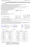
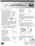
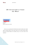
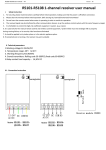
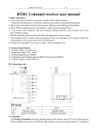
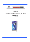
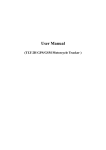
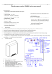
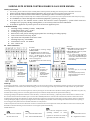
SLIDING GATE OPENER CONTROL BOARD SL1600 USER MANUAL
A5
I Safety Instruction
1.
2.
For security, please read instructions carefully before initial operation; making sure that the power is off before connection.
Please clear the memory before initial operation. (Ref.: Erasing ALL learned/memorized Transmitters)
3. Do not learn the remote control when motor is operating in order to avoid mis-operation.
4.
The received signal may be interfered by other communication devices. (e.g. the wireless control system with the same frequency range)
5. It is forbidden to control the high-risk coefficient equipment / system. (e.g. cranes)
6. It is used only for the manual remote control and wireless control equipment / system which must not
endanger life or property during running failure, or its security risks have been eliminated.
7. It should be applied in dry indoor place or in the electric appliance place.
II Technical Index
1. Working voltage: 220VAC/110VAC,50Hz/60HZ
2. Temperature range: -20℃ to 60℃
3. Loading capacity: 1HP, 250VAC
4. Built-in fuse: 10A, please exchange appropriate fuse according to loading capacity
5. Time of Soft-start & soft-stop: 4S/6S
6. Operation time: adjustable from 10S to 130S
7. Working frequency: 433.92MHz
8. Transmitters stored: 30 -300PCS
9. Size : 150*77*38
III Wire connection
As shown:
A:【12\13】Connector for photocell
protection switch NC contact
B:【10\11】24VAC output can power
supply the photocell.
C: If no need of using photocell,
make connector【12\13】short
circuit with terminated line(the
connector is short circuit when
leave factory)
As shown:
A: 【 1\2\3\4 】 For working voltage
220VAC\110VAC;
B:【5\6】Connector for flash lamp
C: 【8】Connector for motor common
port 1; 【 7 】 Connector for motor
running port 1; 【 9 】 Connector for
motor running port 2.
D: 【7/9】Connector for motor starting
capacitance.
As shown:
DIP switch 2 in
OFF position,
connector
【14\15\16】for
limit switch is
Normal Open
As shown:
DIP switch 2 in
ON position,
connector
【14\15\16】for
limit switch is
Normal Close
As shown:
Connector 【17\18\19\20\21】
for external
close/stop/open/loop control,
control systems is the same as
using transmitter。
IV Set up
4.1 Learning transmitters:Press the learning button, LED is on, enters into the learning / memorizing transmitter process; Press the same button
twice, LED blinks for several times, then off. The learning process is successful. (Ignore this step if transmitter already matches the opener before
delivery):
4.2 Erasing transmitter: Press the learning button, continue pressing for 8s until LED turns off; Release learning button, LED will be on (about 1s)
and then off; the erasing process is successful. (Ignore this step if transmitter already matches the opener before delivery)
4.3 Opening/closing limit adjustment: Remote control the door ( or move the door manually ) , adjust the position of limit device to make sure the
door would touch the limit switch when open or close the door .LED LD5/DL6 in the controller will be off when limit device touches limit switch
4.4 Running time/waiting time adjustment: « Adjust potentiometer T. Normal to change the running time (10-130s) of motor .Adjust it to make the
running time slightly longer (1-2s) than opening time that it needs. Adjust potentiometer T. Wait to change the time that between door opening to
auto-closing(10-130s).This function is available when DIP 1 is at ON position .
4.5 Photocell protection function test: Photocell connector connects the NC contact of photocell switch , DL7 LED turn on after the connection, And
DL7 LED turn off when blocking out the transmit or receive signal of photocell artificially
4.6 DIP Switch set
DIP1:
ON: Auto-close
is effective
V Operation
Instruction
OF: Auto-close is off
DIP3:
DIP2:
ON:External limit NC switch
OFF:External limit NO switch
ON or OFF can change the current
operating
direction
of
motor
(opener can be chosen to install on
right side or left side of the door)
DIP4:
ON:Three button control
OF:Single button control
5.1 Three button control process (DIP 1 at ON position)
STOP
Press transmitter button 1
Press transmitter button 3
键
键
OPEN
Open
Press
Max
limit
transmitter
running
point
button 2
CLOSE
Photocell
Close
Max
protection
limit
running
point
time
time
Press
transmitter
button 2
5.2 Single button control process (DIP 1 at OFF position)
STOP
Press transmitter button 1
OPEN
Press
Open
Max
transmitter
limit
running
button 1
point
time
Description :
Single
button
control
,
press-open-press-stop-press-st
op; Only the learned button is
effective in the transmitter,
original button is not effective
any more when a new button
has been learned in the same
transmitter
(For
example,
button 1 was learned firstly,
button 2 or 3 has been learned
of the same transmitter
afterwards , then button 1 was
not effective any more)
STOP
Press transmitter button 1
键
CLOSE
Model
Press
Close
Photocell
Max
transmitter
limit
protection
running
button 1
point
Frequency
Code
Transmitter stored
time
Voltage
Model
Frequency
Code
Transmitter stored
Voltage
SL1600
433.92Mhz
Rolling
30
220VAC
SL1620
433.92Mhz
Rolling
30
110VAC
SL1601
433.92Mhz
Rolling
300
220VAC
SL1621
433.92Mhz
Rolling
300
110VAC
SL1602
433.92Mhz
Fixed
60
220VAC
SL1622
433.92Mhz
Fixed
60
110VAC
SL1603
433.92Mhz
Fixed
600
220VAC
SL1623
433.92Mhz
Fixed
600
110VAC