1
ICN 2005
Intelligent Conference System
User Manual
DIGITON Ltd.
ICN 2005
Intelligent Conference System
Copyrights
All rights reserved!
No part of this User Manual can be copied, forwarded or translated without the written permit
of the author (DIGITON Ltd.).
Printed in Hungary
May, 2007
Version: 1.4.
2/66
Contents
1.
GENERAL INFORMATION ........................................................................................ 5
1.1. INTRODUCTION .............................................................................................................. 5
1.2. CONFERENCE SYSTEM SERVICES .................................................................................... 5
1.2.1. Core functions.......................................................................................................... 5
1.2.2. Transmitting interpreted speeches........................................................................... 6
1.2.3. Voting facility .......................................................................................................... 6
1.2.4. Chip card identification........................................................................................... 6
2.
SYSTEM ELEMENTS ................................................................................................... 7
2.1. CENTRAL UNIT PEP 3001.............................................................................................. 7
2.1.1. General introduction ............................................................................................... 7
2.1.2. Operation guide ..................................................................................................... 10
2.1.3. Power supply ......................................................................................................... 12
2.1.4. System arrangement and control........................................................................... 12
2.1.5. DIP switches .......................................................................................................... 12
2.1.6. Technical data ....................................................................................................... 13
2.1.7. Connectors............................................................................................................. 14
2.2. MICROPROCESSOR CONTROL UNIT PEP 3002 .............................................................. 16
2.2.1. General introduction ............................................................................................. 16
2.2.2. Operation guide ..................................................................................................... 18
2.2.2.1. Offline operation mode.................................................................................................18
2.2.2.2. Operation mode "Conference control" .........................................................................18
2.2.2.3. Operation mode "Menu"...............................................................................................19
• Conference mode (operation mode for giving the word) ........................................19
• Start vote (starting the vote) ....................................................................................20
• Vote time (time available for voting) ......................................................................21
• Attendance check (checking presence) ...................................................................21
• Start priority (introducing a banning issued by the chairman) ................................22
• DU renumber (readdressing) ...................................................................................22
• Offline .....................................................................................................................23
2.2.3. „CALL” (help request of the interpreter).............................................................. 23
2.2.4. Technical data ....................................................................................................... 23
2.2.5. Connectors............................................................................................................. 24
2.3. CHANNEL DECODER PEP 3006.................................................................................... 24
2.3.1. General introduction ............................................................................................. 24
2.3.2. Operation guide ..................................................................................................... 26
2.3.3. Technical data ....................................................................................................... 27
2.3.4. Connectors............................................................................................................. 27
2.4. POWER SUPPLY UNITS ETP 315 AND ETP 370 ............................................................ 28
2.4.1. General introduction ............................................................................................. 28
2.4.2. Operation guide ..................................................................................................... 28
3/66
2.4.3. Technical data ....................................................................................................... 30
2.4.3.1. Power unit ETP 315..................................................................................................... 30
2.4.3.2. Power unit ETP 370..................................................................................................... 30
2.4.4. Connectors............................................................................................................. 31
2.4.4.1. Power unit ETP 315..................................................................................................... 31
2.4.4.2. Power unit ETP 370..................................................................................................... 31
2.5. CHAIRMAN UNIT HEP 300 .......................................................................................... 32
2.5.1. General introduction ............................................................................................. 32
2.5.2. Operation guide..................................................................................................... 32
2.5.2.1.
2.5.2.2.
2.5.2.3.
2.5.2.4.
2.5.2.5.
Basic functions and transmission of the interpreted languages ................................... 34
Voting possibility......................................................................................................... 35
Chip card identification ............................................................................................... 36
Programming the unit .................................................................................................. 36
Fast addressing............................................................................................................. 37
2.5.3. Technical data ....................................................................................................... 37
2.5.4. Connectors............................................................................................................. 38
2.6. DELEGATE UNITS HEP 301V AND HEP 301VR ......................................................... 39
2.6.1. General introduction ............................................................................................. 39
2.6.2. Operation guide..................................................................................................... 39
2.6.3. Technical data and connectors.............................................................................. 41
2.7. DELEGATE UNIT HEP 301........................................................................................... 42
2.7.1. General introduction ............................................................................................. 42
2.7.2. Operation guide..................................................................................................... 42
2.7.3. Programming the unit ........................................................................................... 44
2.7.4. Technical data and connectors.............................................................................. 45
2.8. INTERPRETER DESK HEP 303 ...................................................................................... 45
2.8.1. General introduction ............................................................................................. 45
2.8.2. Operation guide..................................................................................................... 45
2.8.3. Preparatory steps for programming the interpreter unit ...................................... 49
2.8.4. Programming the interpreter unit when interpreters work alone (single mode) .. 50
2.8.5. Programming the interpreter unit in the case of interpreters working in pairs
(twin mode) ........................................................................................................................ 52
2.8.6. Using the interpreter unit ...................................................................................... 53
2.8.7. Technical data ....................................................................................................... 54
2.8.8. Connectors............................................................................................................. 55
3.
PLACING, CABLING AND SETTING UP THE UNITS OF THE SYSTEM ...... 56
3.1.
3.2.
3.3.
3.4.
3.5.
3.6.
4.
4/66
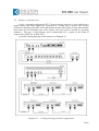
GENERAL INTRODUCTION ............................................................................................ 56
MINIMAL CONFIGURATION .......................................................................................... 57
MINIMAL CONFIGURATION EXTENDED WITH A CONTROL UNIT .................................... 58
NORMAL CONFIGURATION........................................................................................... 59
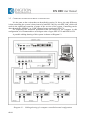
COMPUTER CONTROLLED NORMAL CONFIGURATION ................................................... 60
COMPUTER CONTROLLED SPECIAL CONFIGURATION.................................................... 61
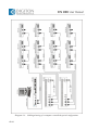
CO-OPERATION WITH INTERPRETATION SYSTEM INFRAPLEX 2005 .... 63
1. GENERAL INFORMATION
1.1. INTRODUCTION
ICN 2005 (ICN = Intelligent Congress Network) is the further developed version of the
previous popular conference system ICN 2000 of DIGITON Ltd. With preserving the
successful design, with significant service extension, the new ICN 2005 conference system is
a favourable value rate representing solution.
The new 32-channel communication system ensures transmission for 31 digital audio
channels and 1 data communication channel. The audio channels offer a voice quality that
meets all the demands with the aid of a transmission of 16 bit/48kHz PCM. The audio
channels can be freely distributed between the languages interpreted and the active
microphones. This means that with the aid of conference system ICN 2005 even such a
system serving 23 languages can be set-up – that meets the interpretation requirements of the
European Union.
When developing the system one of the most important aspects was the principle of modular
extendibility. The cabling and power supply structure can be flexibly adapted from the simple
meetings of a few participants up to Parliamentary systems that serve several hundreds of
people. The delegate units are produced in three different versions, starting with the simple
one that allows the presentation of speeches and ensures loudening, through the model that is
equipped with an LC graphic display, up to the model that ensures chip card identification.
Naturally all these types can be incorporated into the same system.
1.2. CONFERENCE SYSTEM SERVICES
1.2.1. Core functions
The basic sets of the delegate units of the conference system contain a microphone
(HEP 301), a loudspeaker and a "word-requesting" button. The excellent audio quality and
speech understanding is ensured by a decentralised, controlled audio amplification technology
solution. The built-in microphone of the delegate unit has ”cardioid" direction-characteristics
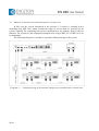
in order to ensure interference-free operation. In the basic set-up (Diagram 1) the system is
made up of a central unit (PEP 3001), chairman (PEP 300) and delegate units (PEP 301..). In
this set-up the system can be operated only in automatic mode. With the aid of power unit
ETP 315 maximum 15, while with the aid of power unit ETP 370 maximum 70 delegate units
can be connected to the system. The maximum number of active microphones that can be
used simultaneously can be set with the aid of central unit PEP 3001.
The main characteristics of the system are the following:
- simple operation
- fast installation
- excellent speech understanding
- aesthetic appearance
- multi-dialogue communication
- several types of microphone activating operation modes
- possibility of connecting external audio recording units
- receiving of the signals of external audio sources
- receiving the signal of external room audio amplifiers
- room-audio output for the purpose of external loudening
- connection of an external participant from a phone line
5/66
1.2.2. Transmitting interpreted speeches
Unit HEP 301 of the conference system allows the simultaneous transmission of even
30 different language interpretations. Channel 31 broadcasts the floor-voice, while channel 32
is for data communication. According to the international prescriptions in each interpreter
booth work facilities have to be ensured for two interpreters simultaneously, for this reason 2
interpreter units are required in each booth. Therefore in the system each interpreter has an
independent interpreter unit, which ensures interpreter shifting within the booth. The system
does also support the interpretation mode of several relay languages.
Naturally the interpreter system is capable of operation if 1 interpreter unit is installed
in each booth.
The translated languages may be listened with the aid of the headphones that is
connected to the delegate unit. Selecting the language and setting the audio volume can be
achieved with the aid of the press-buttons of the delegate unit.
1.2.3. Voting facility
Units HEP 301V of the conference system are equipped with backlit graphic LC
displays, which also ensure a three press-button voting facility for the participants, in addition
to transmitting the interpreted languages. Using chairman unit HEP 300 or processor-based
control panel PEP 3002 it is possible to implement only simultaneous, secret and nameless
voting, while with computer control unit PEP 3004 it is possible to conduct also different
polls, with names and without names, simple and weighted voting as well.
It is possible to read from the graphic LC display of the delegate unit the remaining time
while it is possible to vote and also the result of the vote.
Selecting the interpreted languages and setting the adequate audio volume can be also
done with the aid of the graphic display, which simultaneously displays the abbreviated name
of the selected language as well.
1.2.4. Chip card identification
Units HEP 301VR of the conference system – in addition to the functions that are
described in sections 1.2.3. – have a chip card reader as well, with the aid of which it is
possible to identify the participants with chip cards independently of their delegation desk. It
is only practical to order such a system together with the control unit. In chip card operation
mode it is possible to ask word or vote only after inserting the chip card into the device.
6/66
2. SYSTEM ELEMENTS
2.1. CENTRAL UNIT PEP 3001
2.1.1. General introduction
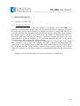
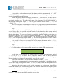
Central unit PEP 3001 is the core element of conference system ICN 2005. It is
required for all the possible configurations. It is the task of the unit to synchronise the system
and to generate the floor audio channel. It is possible to connect to a single PEP 3001 device
even 400 participant and interpreter units, provided the system is adequately set up. Through
the analogue inputs of the unit it is possible to mix the signals of external audio sources as
well to the floor audio, and from its outputs it is possible to connect the signal of the floor
audio channel to an external amplifier or voice recording equipment. The two coaxial output
located on device are for driving the infrared radiators.
The central unit in addition to the above controls the word giving of the word, voting
and it indicates to the speakers the „SLOWLY PLEASE” request of the interpreters. The
"waiting list" is also managed by the central unit, which contains the list of those units, which
did not get the word due to the available channels being occupied. Whenever an occupied
channel is freed the first unit on the waiting list is moved among the units that have got the
word.
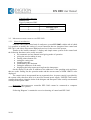
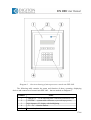
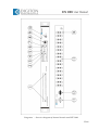
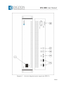
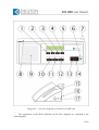
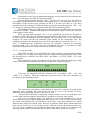
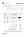
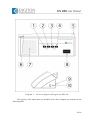
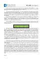
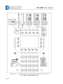
Diagram 1 of the next page shows the overview drawing of unit PEP 3001.
7/66
Diagram 1 - Overview sketch of unit PEP 3001
8/66
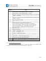
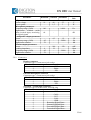
The following table contains the name and function of those operator and display
components and connectors of central unit PEP 3001, which are marked in Diagram 1.
Number
1
2
3
4
5
6
10
Name
„SYSTEM” – volume regulator of the system
„LINE” – volume regulator of the line level input
„EXT. MIC.” – volume regulator of the external microphone input
„TAPE” – volume regulator of the tape recorder input
„TELEPHONE” – volume regulator of the phone input
„LANG. EXT.” – volume regulator of the external language input
„NOM LIMIT” – switch setting the number of microphones that
may be switched on simultaneously
„SPEAKERS” – volume regulator of the loudspeakers of the units
Output control display of the signal forwarded to the loudspeakers
of the units
„MAIN” – volume regulator of the line level output
11
Outgoing control meter of the line level output
12
„HEADSET” – volume regulator of the headset output
13
Status indicating LEDs
14
Headset connector
15
„POWER” – supply voltage main switch (it has a function only
when ETP 315 is applied)
16
„DC 30V” – supply voltage connector for connecting unit ETP 315
17
„SYSTEM 1” – system connector
18
„SYSTEM 2” – system connector
19
„INFRA OUT” – coaxial outputs to the infrared radiators
20
„TAPE OUT” – output for a voice recording device
21
„TAPE IN” – input for a voice recording device
22
„EFFECT OUT” – output for connecting an external device
23
„EFFECT IN” – input for connecting an external device
24
„EXT. LANG. IN” – connector of external language input
25
„TEL. OUT” – connector of phone output
26
„TEL. IN” – connector of phone input
27
„LINE OUT” – connector of line level output
28
„LINE IN” – connector of line level input
29
„EXT. MIC. IN” – input connector of external microphone
7
8
9
9/66
2.1.2. Operation guide
Starting up the operation of the central unit – after connecting power unit ETP 315 – is
done with power voltage switch marked „POWER” (15), the execution of which is indicated
by green photo-diode „POWER” (13) of the device. After switching on, yellow photo-diodes
„REMOTE” and „NOM LIMIT” (13) flash alternatively on the front panel of the central unit
for some seconds – during the period of synchronising –, and then after synchronisation is
completed both go out.
During operation the flashing of LED marked „REMOTE” (13) indicates data
transmission, while the flashing of LED marked „NOM LIMIT” (13) indicates a
synchronisation error.
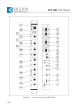
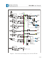
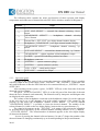
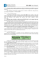
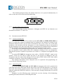
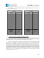
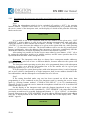
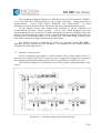
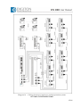
Unit PEP 3001 also contains a 6 channel analogue mixer, the block scheme of which is
presented in Diagram 2 of the next page. The signal entered through the inputs of the mixer
(„SYSTEM”, „LINE”, EXT. MIC.”, „TAPE”, „TELEPHONE”) can be mixed to the
collecting bus ("NORMAL BUS") of the floor voice with volume regulators (1-5) that belong
to these inputs. The Floor Voice generated this way on one side is forwarded to channel 0 of
the PPM modulator of the unit, and on the other side it appears on outputs marked „LINE
OUT” (27) and „TAPE OUT” (20) of the device.
The volume regulator of mixer marked „SYSTEM” (1) regulates the aggregated signal
of the switched on microphones of the conference system, which signal is subsequently
forwarded to the collecting bus ("NORMAL BUS") of the floor voice. The level of the floor
voice signal ("FLOOR") that is forwarded from here to the built-in loudspeakers of the
conference system can be regulated with volume regulator marked „SPEAKERS” (8). The
level of the signal forwarded to the loudspeakers – that may be controlled with the control
meter (9) located next to the regulator – has to be set in such a manner that the red colour
LED should flash only for a short while even in the case of louder voices.
The level of the floor voice signal appearing on output marked „LINE OUT” (27) can
be set to the value desired with the volume regulator marked „MAIN” (10) located on the
front panel, which can be also visually checked on the control meter (11) that is located next
to the regulator. The level of the outgoing signal has to be set in such a manner, that the red
colour LED of the control meter should flash for a very brief time only in the case of very
loud voices, and it should not be lit continuously. This output can be used for controlling the
floor loudspeakers of the given room.
With the aid of the headset connected to the headset socket (14) of the front panel the
floor voice ("FLOOR") can be checked acoustically as well. The volume of the signal
forwarded to the headset can be set to the desired value with the aid of the volume regulator
"HEADPHONE" (12) that is located next to the connector.
The central unit allows the receiving of external phone lines as well. However a special
connecting cable is needed for this, prepared for this purpose. The signal that goes to the
headset of the hand-speaker of the phone device has to be introduced to input „TEL. IN” (26)
of unit PEP 3001, the volume of which can be set with volume regulator marked
„TELEPHONE” (5). And to the input of the hand-speaker of the phone device receiving the
signal of the microphone output marked „TEL. OUT” (25) of the central unit has to be
introduced.
It is also possible to mix the input signals of PEP 3001 to an "EFFECT BUS", and from
there to forward the mixed signal to an external unit (e.g. excitation inhibitor) through
connector „EFFECT OUT” (22). The signal given out to the external unit can be re-entered
into the central unit with the aid of connector „EFFECT IN” (23).
10/66
Vcc
EFFECT BUS
NORMAL BUS
FLOOR
DIRECT/ TELEPHONE BUS
MAIN adj.
NORMAL (OFF)
-40dBV
EXT.MIC. adj.
2. DIP
EFFECT (ON)
0dBV
HEADPHONES
adj.
LINE OUT
SPEAKERS
adj.
NORMAL (OFF)
LINE adj.
TAPE OUT
-10dBV
0dBV
1. DIP
EFFECT (ON)
Digitally controlled
by NOM. ATT.
0dBV
A
D
SYSTEM BUS
HEADPHONES
TEL. adj.
TEL. OUT
0dBV
0dBV
EFFECT OUT
0dBV
NORMAL (OFF)
-10dBV
TAPE adj.
CH0
3. DIP
EFFECT (ON)
D
A
INFRA OUT
A
NORMAL (OFF)
SYSTEM adj.
D
4. DIP
EFFECT (ON)
CH1
CH2
CH3
CH4
CH5
CH6
PPM modulator
INFRA OUT
CH1-CH6
A
D
INSERT control
0dBV
EXT.LANG. adj.
CH1
Diagram 2 - Block scheme of the analogue part of central unit PEP 3001
11/66
The level of the external language entered into input marked „EXT. LANG. IN” (24)
can be set to the desired value with volume regulator marked „LANG. EXT.” (6). The signal
connected here appears on language channel 1 in case this function is switched on with DIP
switch 7 located at the bottom of the device.
Information related to the other cables that are to be connected to unit PEP 3001
(system cable and coaxial cable) is included in Section 3.
2.1.3. Power supply
−
−
−
The following power units ensure the power supply voltage of the system:
When using unit ETP 315 the power supply voltage gets into the system through central
unit PEP 3001, which ensures the power supply of maximum 15 units through 2 different
branches.
In the case of unit ETP 370 the power supply voltage goes directly to the system cable,
which together with unit PEP 3001 ensures the power supply of maximum 70 units
through 3 branches.
With using several ETP 370 units it is possible to establish a system that consists of
maximum 400 units.
2.1.4. System arrangement and control
Only one PEP 3001 unit can be used in the system. The PEP 3001 central unit has two
system cable connectors („SYSTEM 1” and „SYSTEM 2”), which allows the installation of
the units on two branches. Both branches have to be continuous, which can only consist of the
own elements of system ICN 2005 and their connected cables.
The PEP 3001 central unit is capable of executing the following basic controlling tasks itself:
− The number (from 1 to 30) of simultaneously switched microphones can be set („NOM
LIMIT”)
− 2 different automatic word giving methods can be selected
− Managing voting started by the Chairman
− Controlling the infra-modulator
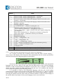
2.1.5. DIP switches
The DIP switches located at the bottom of the device and their functions are included in the
following table.
Number of
the switch
1
2
3
4
5
6
7
8
12/66
Name
LINE IN
EXT. MIC. IN
TAPE IN
SYSTEM BUS IN
SYSTEM BUS OUT
LINE OUT
EXT. LANG.
Word giving method
Switch setting
Off
for „NORMAL BUS”
for „NORMAL BUS”
for „NORMAL BUS”
for „NORMAL BUS”
NOM damping off
NOM damping off
Switched off
Automatic 1
On
for „EFFECT BUS”
for „EFFECT BUS”
for „EFFECT BUS”
for „EFFECT BUS”
NOM damping on
NOM damping on
Switched on
Automatic 2
The meaning of the names included in the above table is the following:
„NORMAL BUS”/„EFFECT BUS”
It can be selected with DIP switches of serial numbers 1–4 in such a manner that the
signals of inputs „LINE IN”, „EXT. MIC. IN”, „TAPE IN” and „SYSTEM BUS IN” should
be forwarded to either the „NORMAL BUS” or the „EFFECT BUS”.
NOM damping:
In its switched on condition it changes the volume of the loudspeakers of the delegate
units depending on the number of active microphones, in order to avoid acoustic pop noise (as
the number of active microphones increases it reduces the volume of the loudspeakers of the
delegate unit). With switch 5 this attenuation is introduced on output marked „SYSTEM BUS
OUT” that is at the signal that is forwarded to the built-in loudspeakers of the delegate units,
while with switch 6 for example NOM attenuation can be activated on output „LINE OUT”
(27) that is for amplifying the floor voice.
EXT. LANG:
When DIP switch 7 is switched on, the signal forwarded to input connection marked
„EXT. LANG. IN” (24) is introduced to channel 1 of the system, while if it is switched off,
then channel 1 can be used for the interpreted languages.
Word giving methods
With DIP switch 8 it is possible to select from the following two different ways of
giving the word:
Automatic 1:
The microphone of the word-asking participant is immediately and automatically
switched on, if there is available free channel within the system. In contrary cases, if there is a
lower priority speaker, then the word will be taken away from the that lower priority speaker,
which has talked for the longest, and in the rest of the cases the word asking participant is
included in the waiting list.
Automatic 2:
The microphone of the word asking participants is immediately and automatically
switched on, if there is a free channel available within the system. In contrary cases, if there is
an identical or lower priority speaker, then the word is taken away from the one that has
talked for the longest, and in the rest of the cases the word asking participant is included in
the waiting list.
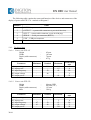
2.1.6. Technical data
Height
Width
Depth (with connectors)
Mass
:
:
:
:
44 mm (1 HE)
482 mm (19”)
108 mm
1450 g
13/66
Parameter
DC parameters
Power voltage
Power uptake
Inputs parameters
„LINE IN” input level
„LINE IN” impedance
„TELEPHONE IN” input level
„TELEPHONE IN” impedance
„EFFECT IN” input level
„EFFECT IN” impedance
„TAPE IN” input level
„TAPE IN” impedance
„EXT. LANG IN” input level
„EXT. LANG IN” impedance
„EXT. MIC. IN” input level
„EXT. MIC. IN” impedance
„EXT. MIC. IN” input noise level
to the value desired with an 150 Ώ
drive (E.I.N.)
Outputs parameters
„LINE OUT” output level
„TELEPHONE OUT”output level
„EFFECT OUT” output level
„TAPE OUT” output level
Load impedance for outputs
Relation of signal-noise at the
outputs (EXT. MIC. volume
reduced)
Frequency range (-3dB)
Headset output parameters
Power
Load impedance
Frequency range (-3dB)
Signal-noise ratio
Minimum Nominal Maximum Measurement
unit
16
3
48
-
55
4
V
W
-
0
20
0
20
0
20
-10
20
0
20
-40
20
+6
+6
+6
-4
+6
-34
-
dBu
kOhm
dBu
kOhm
dBu
kOhm
dBu
kOhm
dBu
kOhm
dBu
kOhm
-
-124
-
dBu
-
0
0
0
-10
1
+6
+6
+6
-4
-
dBu
dBu
dBu
dBu
kOhm
88
90
-
dB
20
-
20000
Hz
8
45
70
90
32
-
200
22000
-
mW
Ohm
Hz
dB
2.1.7. Connectors
Power supply voltage
Type of connector: DC power connector
Number of contacts
Function
1
VCC
2
GND
14/66
Audio frequency inputs and outputs
LINE IN, TEL. IN, EXT. LANG. IN, EXT. MIC. IN
Type of connector: XLR socket
Number of contacts
Function
1
GND
2
Audio 3
Audio +
LINE OUT, TEL. OUT
Type of connector: XLR plug
Number of contacts
1
2
3
Function
GND
Audio Audio +
EFFECT IN, EFFECT OUT
Type of connector: 6.3 mm stereo jack socket
Number of contacts
Function
1
GND
2
Audio 3
Audio +
TAPE IN, TAPE OUT
Type of connector: RCA socket
Number of contacts
1
2
Function
GND
Audio
HEADPHONE - headset connector
Type of connector: 6.3 mm stereo jack socket
Number of contacts
Function
1
GND
2
Right
3
Left
System cable connector
SYSTEM 1, SYSTEM 2
Type of connector: D-SUB9 socket
Number of contacts
Function
1
GND
2
CAN+
3
VCC
4
CAN5
GND
6
Returning Digital data +
7
Returning Digital data 8
Forwarded Digital Data +
9
Forwarded Digital Data 15/66
Coaxial cable connector
INFRA OUT
Type of connector: BNC
Number of contacts
1
2
Function
PPM data signal
GND
2.2. MICROPROCESSOR CONTROL UNIT PEP 3002
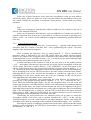
2.2.1. General introduction
Unit PEP 3002 is the control unit of conference system ICN 2005, with the aid of which
it is possible to modify the setting of several functions that are integrated into central unit
PEP 3001, and it does also ensure additional services for the user of the system.
Thanks to the backlit contrast LC display and simple menu system of the control unit
the following functions can be easily accessed:
• two automatic and one manual word giving mode of operation
• giving the word or taking it away
• starting a three button vote
• setting the voting time
• checking presence
• prohibition by the chairman
• setting the addresses of the units
• displaying the help request arriving from the interpreters
On the display of the unit in addition to the addresses of the speaking units and those
that are on the waiting list, the operation mode and the current status of NOM LIMIT is also
displayed.
The control unit is incorporated into an ergonomic box, its power supply is provided by
the system cable, therefore there is no need for external power supply. Unit PEP 3002 can be
connected anywhere along the chain of the delegate and interpreter units serially concatenated
serially on the system cable.
Important! Microprocessor controller PEP 3002 cannot be connected to computer
controlled conference systems.
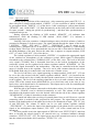
Following Diagram 3 contains the overview drawing of control unit PEP 3002.
16/66
Diagram 3 - Overview drawing of microprocessor control unit PEP 3002
The following table contains the name and function of those operating, displaying
devices and connectors of control unit PEP 3002 – that are marked on Diagram 3.
Number
Name
1
„PRIORITY” – LED indicating that a chairman prohibition is on
2
„SYSTEM” – system cable connector (9 pole D-SUB plug-socket)
3
4x20 character LC display with backlighting
4
„F1 – F4” – function buttons
5
Numeric keyboard
17/66
2.2.2. Operation guide
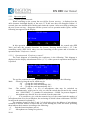
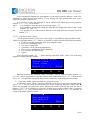
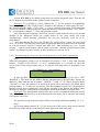
2.2.2.1. Offline operation mode
When switching on the system the text Offline System starting... is displayed on the
4x20 character backligth display of the unit (3). If this text does not disappear within 1-2
seconds, then one should check cabling and restart the system. After successful switching on
the text System starting... disappears and the system is set to operation mode Offline, and the
following text appears on the display.
Offline
Online
F1
F2
F3
F4
In this operation mode the conference system is controlled by the central unit (PEP
3001) and only the essential functions do operate. Pressing button Online („F1”) the
controlling centre (PEP 3002) takes over the controlling of the system and it switches to
operation mode "Conference control".
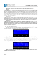
2.2.2.2. Operation mode "Conference control"
The basic diagram of controlling the conference is the following. This diagram is
displayed on the display when button Online („F1”) of the system in operation mode Offline
is pressed:
Mode:A1 Nom: 2 [
A5
>A4 P2
]
Menu
<
>
Mic
F1
F2
F3
F4
The top line contains the system parameters, and their meaning is the following:
Mode - From of giving the word, which may be
-M
- giving the word manually
- A1 - giving the word automatically No 1
- A2 - giving the word automatically No 2
Nom
- The number (from 1 to 30) of microphones that may be switched on
simultaneously, which can be only set with the switch that located in the central
unit „NOM LIMIT” (7) (number of microphones = NOM). In present diagram 2
microphones are allowed for to be switch on at the same time.
[ ] It is possible to give with the numeric keys of the control unit the number of
microphones that are to be switched on, the activating of which is done with button "ENTER"
located on the numeric keyboard (5).
The numbers located in lines 2 and 3 of the display gives the address of microphones
switched on and the address of those that are on the waiting list, while the letters preceding
them indicate their statuses according to the following:
„A” - Switched on microphone (active)
„P”
- Microphone on waiting list (passive)
18/66
In the mentioned diagram the microphones of the units with the address 5 and 4 are
switched on, while the unit with address 2 is on waiting list. The symbols that close in A4
shows the position of the cursor.
It is possible to enter the function of line 4 marked with labels by pressing function
buttons „F1” – „F4” (4) as follows:
Menu - it is possible to enter the menu by pressing button „F1”
</>
- it is possible to select from among the units that are displayed in lines 2 and 3 with
buttons „F2” and „F3”
Mic
- it is possible to give the word or take the word away from the selected unit with
button „F4”
2.2.2.3. Operation mode "Menu"
From operation mode "Conference controlling" it is possible to enter operation mode "
"Menu" by pressing button „F1”, where it is possible to select from the following sub-menus:
• Conference mode (operation mode for giving the word)
• Start vote (starting the vote)
• Vote time (voting time)
• Attendance check (checking attendance)
• Start priority (prohibition of the chairman)
• DU renumber (re-addressing)
• Offline
After pressing button „F1” – when entering operation mode "Menu" the following
diagram is displayed in the display:
>Conference mode<
Start vote
Vote time
Select ↑
↓
Exit
F1
F2
F3
F4
Moving between the submenu items (scrolling) can be achieved with buttons ↑/↓
(„F2/F3”) and it is possible to enter the selected item with button Select („F1”). With button
Exit („F4”) it is possible to return to the previous conference controlling operation mode.
•
Conference mode (operation mode for giving the word)
In Operation mode "Menu" selecting submenu Conference mode, then pressing button
Select („F1”) we may enter this sub-menu (see on the following diagram), where sign ◄
shows the currently set conference mode. Moving the cursor up/down and with the aid of
buttons „F2/F3” it is possible to select the relevant word giving method, and by pressing
button Select („F1”) the selected mode is set. With button Menu („F4”) it is possible to
return to the menu operation mode.
Manual◄
>Automatic1<
Automatic2
Select ↑
↓
F1
F2
F3
Menu
F4
19/66
In submenu Conference mode the following word giving methods may be set:
Manual:
Units of priority „0” will not get the word automatically, but will be put on a waiting list, and
the word can be given to them only from the control centre. However, units of higher priority
do get the word automatically. In the case of several higher priority units, and if there is no
free channel, then the word will be taken away from the lowest priority unit, who had spoken
for the longest period. If there are only units of higher priority switched on, then the word
requestor is put on a waiting list.
Automatic 1:
If there is a free channel, then the speaker automatically gets the word. If there is no free
channel, and if there are speakers of lower priority, then the word will be taken away from the
speaker who has spoken for the longest period, otherwise the speaker is put on a waiting list.
Automatic 2:
If there is a free channel, then the speaker gets the word automatically. If there is no free
channel, and provided there is a speaker of identical or lower priority, then from among them
the word will be taken away from the one who has been talking for the longest, otherwise the
speaker is put on the waiting list.
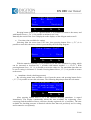
•
Start vote (starting the vote)
Selecting item Start vote from the menu, then pressing button Select („F1”) we can
enter this sub-menu. The diagram of this sub-menu is the following:
3 button vote
Start
F1
Menu
F2
F3
F4
It is possible with button Start („F1”) to start voting, while with button Menu („F4”), it
is possible to return to the menu.
After starting the vote, the following diagram is displayed on the screen. With the aid of
this screen it is possible to monitor the momentary status of the vote, and the time that is still
left for voting. With button Stop („F4”) voting can be interrupted at any time.
Yes
0
F1
Voting...
No Abst Time:
0
0
0:12
Stop
F2
F3
F4
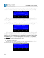
When the voting time is over, the result of voting appears on the display of the central
controller in the following form:
20/66
Vote results
Yes
No Abst
2
1
1
Menu
Restart
F1
F2
F3
F4
Keeping button Menu („F1”) pressed down, it is possible to return to the menu, and
with button Restart („F4”), it is possible to initiate a new vote.
Naturally the result of the vote is displayed on the displays of the delegate units as well.
•
Vote time (time available for voting)
Selecting from the menu item Vote time, then pressing button Select („F1”) it is
possible to enter this sub-menu, which is presented by the following diagram:
Vote time: 0:27
Menu
F1
-
+
Save
F2
F3
F4
With the numeric keyboard (5) it is possible to set the time available for voting, which
can be increased or decreased by 1 seconds with buttons marked -/+ („F2/F3”). With
pressing button Save („F4”) it is possible to store the value set. The maximum time that can
be set for voting is 4 minutes 15 seconds. Pressing button Menu („F1”) it is possible to return
to the menu.
•
Attendance check (checking presence)
By selecting menu item Attendance check from the menu, and pressing button Select
(„F1”) it is possible to enter this sub-menu. The following diagram presents this sub-menu:
Attendance check
Time remaining: 0:17
No. of attendee:
7
Menu
Exit
F1
F2
F3
F4
After pressing button Select („F1”) the function checking attendance is started
immediately. The display continuously shows the time available for registering (Time
remaining) and the number of those, who have already registered (No. of attendee). The time
available for checking presence is identical with the time that was previously set for voting,
and it cannot be set separately.
21/66
After the expiry of the period that is set for checking attendance, the following diagram
is displayed on the screen showing the number of registered participants (No. of attendee):
Attendance check
No. of attendee: 25
Menu
Exit
F1
F2
F3
F4
Pressing one of the buttons „YES”, „NO” or „ABST” can do checking attendance or
„ABST”. It is possible to return to the menu with button Menu („F1”), while with button Exit
(„F4”) it is possible to return to the conference controlling operation mode.
•
Start priority (introducing a banning issued by the chairman)
It is possible to enter this sub-menu by selecting menu item Start priority, then pressing
button Select („F1”). When entering this sub-menu the following diagram is displayed:
Priority mode
Reset
F1
Restore
F2
F3
F4
At this point on the units of priority „0” the red LED starts to flash, indicating that the
microphones of the given units are forbidden (they cannot be switched on). It is possible to
return from this prohibition with the aid of the control center in two ways to conference
controlling mode. By pressing button Restore („F4”) the microphones that have been
switched on prior to the prohibition issued by the chairman are switched on again, while by
pressing button Reset („F1”) the microphone of all the units of priority „0” is switched off.
Comment: By pressing button „PR” (Priority) located on the unit of the chairman,
naturally it is also possible to enter this operation mode.
•
DU renumber (readdressing)
Selecting item DU renumber from the menu, and pressing button Select („F1”) it is
possible to enter this menu, the diagram of which is the following:
Renumbering devices
Device number: 1
Menu
F1
22/66
-
+
Exit
F2
F3
F4
When entering the menu item all the photo-diodes (LED) of all the delegate and
chairman units of the system starts to flash and at this point it is possible to overwrite the
addresses of the units (reset). The starting address to be set can be selected with buttons -/+
(„F2/F3”) or it may be given by the numeric key-board (5). This address set will be given to
the unit the microphone button of which will be first pressed. When pressing the microphone
button of the next unit, the address of the given unit will be automatically one greater,
however it is also possible to give other address. After setting the addresses the units are
returning to their basic status. Pressing button Menu („F1”) it is possible to return to the
menu, while pressing button Exit („F4”) it is possible to return to the conference-controlling
mode.
•
Offline
Selecting the last item Offline of the menu, and pressing button Select („F1”), it is
possible to exit operation mode Online. In this case the controlling of the conference system is
taken over by central unit PEP 3001.
Pressing button Exit („F4”) it is possible to return to the conference controlling
operation mode.
2.2.3. „CALL” (help request of the interpreter)
With keeping button „CALL” of the interpreter unit for at least 3 seconds continuously,
the interpreters may ask technical assistance from the technician operating the system. In this
case on the display of the controlling unit the following diagram appears, which also indicates
the address of the interpreter unit that asks the help:
Call: interpreter
3
Exit
F1
F2
F3
F4
At the same time the complete display flashes as well in order to draw the attention of
the technician to the request. It is possible to exit from here with button Exit („F4”), and in
this case the assistance requests are deleted.
2.2.4. Technical data
Height
Width
Depth (with connectors)
Mass
Parameter
Power supply voltage
Power uptake
:
:
:
:
100 mm
157 mm
200 mm
691 g
Minimum
Nominal
Maximum
9
0,8
48
1
55
1
Measurement
unit
V
W
23/66
2.2.5. Connectors
The „SYSTEM 1” and „SYSTEM 2” marked connectors if the device are D-SUB9
plug and socket, the wiring of which is identical with the connectors of unit PEP 3001 of the
same marking (see section 2.1.7).
2.3. CHANNEL DECODER PEP 3006
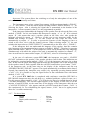
2.3.1. General introduction
The task of the channel decoder PEP 3006 is to decode all the 31 digital channels of the
ICN 2005 conference system into the analog format. The unit asures this way the possibility
of listening and recording simultaneously all translated languages. The languages appear in
RCA connectors marked “CH0-CH30” on the backboard of the unit in analog format. Tape
recorder and multichannel digital soundrecorder can be connected to these lines level sound
frequency outputs.
Aditionaly there is an analog line output “EXT LINE”on wich the preset channel can be
selected.
Using the connected headphones the channels of the system can be checked
acoustically.
The power supply of PEP 3006 is assured via system cables, it is not demanded another
external power supply source.
Important! For an adequate working the channel decoder has to be connected to the
„SYSTEM 2” plug of PEP 3001 basic unit.
One of the possible configurations of the system is showed in Diagram 12, section 3.4.
The channel decoder is built in a standard house (as the basic unit) to be inserted in
rack case.
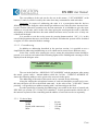
The Diagram 4 on the next page shows the overview drawing of channel decoder
PEP 3006.
24/66
Diagram 4 - Overview diagram of channel decoder unit PEP 3006
25/66
The following table contains the name and function of those operator and display
components and connectors of channel decoder PEP 3006, which are marked in Diagram 4.
Number
Name
1
„ACTIVE CHANNELS” –green LED indicating the active channel
2
„EXT. LINE SELECT” – external line channel selecting ”down”
button
3
„HEADPHONE
”down”button
4
External line („EXT. LINE”) two digits channel number display
5
Headphones („HEADPHONE”) two digits channel number display
6
„HEADPHONE SELECT” – headphones channel selecting ”up”
button
7
„EXT. LINE SELECT” – external line channel selecting ”up” button
8
„HEADPHONE” – volume regulator of the headphones output
9
„POWER” –green LED indicating switched on status
10
Headphones connector
11
„SYSTEM 1” – system connector (plug)
12
„SYSTEM 2” – system connector (socket)
13
„CH0 – CH30” – sound analog output
14
„EXT. LINE” – external line output
SELECT”
–
headphones
channel
selecting
2.3.2. Operation guide
Similary to the other units of the system, the connection of the PEP 3006 is possible
with dasy chain of the system cable via the „SYSTEM 1” and „SYSTEM 2” connectors. The
only main difference is that the PEP 3006 has to be connected directly to „SYSTEM 2” output
of PEP 3001.
After swiching on the system, a green „POWER” LED (9) on the front side of the unit
shows the swich on status.
The green „ACTIVE CHANNELS” LED (1) on the left part of the front side of the unit
shows the active channels used momently. The channels used by interpreter and delegate units
are displayed at the same time.
The volume of the headphones connected to the headphone output (10) on the right part
of the unit can be set to the adequate level with volume regulator of the output (8). By
pressing up and down the headphones channel selector buttons (3) and (6) marked
“HEADPHONES SELECT” is possible to listen the desired channel. The number of the
selected channel is visible on the two digits display, between the two press-buttons (5).
The signal wich appears on the „EXT LINE” (14) output of the unit can be adjustable
by pressing down respectively up the external channel selecting buttons (2) or (7) marked „„EXT LINE SELECT”. The chosed number of channels appears on the twoo digits display
(4) between the buttons.
In case of pressing the channel sellector buttons (3,4 and 6,7) longer the number of the
choosed channel is changing continuously up or down depending on the pressed buttons.
26/66
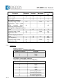
2.3.3. Technical data
Height
Width
Depth (with connectors)
Weight
:
:
:
:
Parameter
Minimum
DC parameters
Power voltage
16
Power uptake
2
Line level output parameters
Output level
Frequency range (-3dB)
20
Signal noise ratio (S/N)
70
Distortion (THD)
Headset output parameters
Power
Load impedancy
8
Frequency range (-3dB)
45
Signal noise ratio
70
44 mm (1 HE)
482 mm (19”)
108 mm
1150 g
Nominal
Maximum
Dimension
48
55
3
V
W
0
-
+6
20000
0,1%
dBu
Hz
dB
dB
90
32
-
200
20000
-
mW
Ohm
Hz
dB
2.3.4. Connectors
Audio frequency outputs:
CH0 – CH30, EXT. LINE
Type of connector: RCA socket
Number of contacts
1
2
Function
GND
Audio
HEADPHONE – headset connector
Type of connector: 6,3 mm stereo jack socket
Number of contacts
Function
1
GND
2
Right channel
3
Left channel
System cable connectors:
SYSTEM 1, SYSTEM 2
Type of connectors: D-SUB9 plug, D-SUB9 socket
See the PEP 3002 connector description as the same number of contacts
(section 2.2.5 respectively 2.1.7)
27/66
2.4. POWER SUPPLY UNITS ETP 315 AND ETP 370
2.4.1. General introduction
Power supply units ETP 315 and ETP 370 ensure the needed power voltage for the
units of conference system ICN 2005. Device ETP 315 ensures power supply for maximum
15 units, while device ETP 370 ensures power supply for maximum 70 units through 2 or 3
branches.
An arbitrary number of devices ETP 370 may be used within a system.
Important! To one branch maximum 35 units can be connected and the length of a
branch cannot exceed 100 meters. In respect of the number of the units each device
(controlling unit, delegate unit, chairman unit, interpreter unit, channel decoder) has to be
taken into consideration.
2.4.2. Operation guide
When using device ETP 315, the power voltage is introduced into the system through
central unit PEP 3001. This device is able to ensure the power supply of 15 units through 2
different branches. In the case of device ETP 370, the power is introduced into the system
directly. This device is able to ensure the power supply of max. 70 units, together with unit
PEP 3001 altogether through 3 branches.
By using several ETP 370 devices it is possible to set-up a system that contains max. 400
units.
Important! Each branch has to be continuous, and they may be made up of only the
own elements and cables of system ICN 2005. A closing element has to be inserted into the
free connector of the last unit of each branch, otherwise the system is not synchronised.
The overview drawing of power supply device ETP 370 can be seen on Diagram 5
located on the next page.
When using device ETP 370 a unit has to be connected to at least one of the outputs
marked „OUTPUT” (2), otherwise the system will not operate. A closing element has to be
inserted to the outputs of the system cables of PEP 3001 and ETP 370 that may be left free.
Controlling computer PEP 3004 can be connected to connectors marked „SERIAL” (4) or
„USB” (5) of the unit. In this case the PC program running under Windows XP executes the
controlling of the conference system.
On central unit PEP 3001a yellow colour LED labelled „REMOTE” indicates that the
controlling of the conference system had been taken over by controlling unit PEP 3002 or
PEP 3004. In one system at any one time only one ETP 370 device can be connected tot he
computer, and „SERIAL” (RS232) and „USB” controlling cannot be used simultaneously.
The „SERIAL” controlling cable should be connected only in switched off status.
Important! Units PEP 3002 and PEP 3004 cannot be used simultaneously for
controlling the system. At any one time only one controller can be connected to the system.
The value of Nom-limit can be set only from the central unit.
28/66
Diagram 5 - Overview diagram of power supply unit ETP 370
29/66
The following table contains the name and function of the devices and connectors of the
display of power unit ETP 370 – marked on Diagram 5.
Number
Name
1
„POWER” – power switch
2
„OUTPUT” – system cable connector (9 pole D-SUB socket)
3
„INPUT” – system cable connector (9 pole D-SUB plug)
4
„SERIAL” – serial port connector (RS232)
5
„USB” – USB port connector
6
Network connector socket
2.4.3. Technical data
2.4.3.1. Power unit ETP 315
Height
Width
Depth (with connectors)
Mass
Parameter
AC input voltage
AC input power
AC input frequency
DC output voltage
DC output power
AC input voltage
AC input power
AC input frequency
DC output voltage
DC output power
30/66
45 mm
145 mm
70 mm
475 g
Minimum
Nominal
Maximum
100
-
230
50
48
-
240
1,5
60
66
2.4.3.2. Power unit ETP 370
Height
Width
Depth (with connectors)
Mass
Parameter
:
:
:
:
:
:
:
:
Measurement
unit
V
A
Hz
V
W
88 mm (2HE)
482 mm (19”)
123 mm
3500 g
Minimum
Nominal
Maximum
88
47
41
-
230
50
48
-
264
5
63
56
310
Measurement
unit
V
A
Hz
V
W
2.4.4. Connectors
2.4.4.1. Power unit ETP 315
Power voltage
Type of connector: DC power voltage connector
Number of contacts
Function
1
VCC
2
GND
Grid connection
Connector type: IEC C14
Number of contacts
N
L
GND
2.4.4.2. Power unit ETP 370
Grid connector
Type of connector: IEC C14
Number of contacts
N
L
GND
Function
null
phase
protective ground
Function
null
phase
protective ground
INPUT, OUTPUT – system cable connector
Type of connector: INPUT - D-SUB9 plug, OUTPUT - D-SUB9 socket
Number of contacts
Function
1
GND
2
CAN+
3
VCC
4
CAN5
GND
6
Returning digital data +
7
Returning digital data 8
Forwarded digital data +
9
Forwarded digital data SERIAL – controller connector
Type of connection: RJ11 4/4
Number of contacts
1
2
3
4
Function
GND
TxD
GND
RxD
31/66
USB – controller connector
Type of connector: USB-B
Number of contacts
1
2
3
4
Function
+5V
USB DataUSB Data+
GND
2.5. CHAIRMAN UNIT HEP 300
2.5.1. General introduction
Chairman unit HEP 300 is one of the basic units of conference system ICN 2005. This
unit is put in front of the chairman conducting the conference.
The unit has a built-in microphone and loudspeaker, which allow the forwarding of the
voice of the chairman towards the other units of the system and simultaneously forwards the
voice of the other speakers to the chairman. The microphone switch located on the unit of the
chairman always switches on the microphone of the chairman immediately, independently of
the operation mode set. With the aid of the press buttons located on the unit it is possible to
switch on the prohibition issued by the chairman and to start voting as well. Voting is done
with the aid of the 3 press buttons located on the device. Device HEP 300 is suitable for
taking over maximum 30 interpreted languages and the room voice as well, which may be
listened to through the headset that is connected to the device. A chip card reader is also
included in the unit, with the aid of which it is possible to identify the user of the device in the
case of a computer controlled conference.
The backlit graphic LC display facilitates using the device and displays its current status
and the result of the vote.
The priority level of the units can be set, through this a priority order can be set between
the different level chairman, and vice-chairman units.
2.5.2. Operation guide
In ICN 2005 systems the chairman unit(s) can be connected with the aid of the 9 pole
D-SUB connectors (16) located on their backside and the installed system cables to the other
units and to the central unit. The units of the conference system starting with the central unit
(PEP 3001) are concatenated serially after each other, however, at the last unit a closing
element must be used.
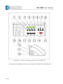
The overview diagram containing the displaying, operating devices of the chairman
unit can be seen on Diagram 6 on the next page.
32/66
Diagram 6 - Overview diagram of chairman unit HEP 300
The explanation of the labels indicated on the above diagram are explained in the
following table:
33/66
Number
Name
1
2
Head-set audio volume regulating button – downwards
Head-set audio volume regulating button – upwards
Selection button of the interpreted language channel forwarded to the
headset – downwards
Selection button of the interpreted language channel forwarded to the
headset - upwards
Backlit, graphic LC display
„VOTING START” – button for starting the vote
Indicating light at the end of the microphone arm:
Green colour lit continuously – microphone switched on
Green colour flashes – signal „SLOWLY PLEASE”signal coming from
the interpreter
Red colour continuously lit – asking the word status (waiting list)
Red colour flashes – prohibition issued by the chairman
Microphone arm
Built-in loudspeaker
„YES” – voting button – yes
„NO” – voting button – no
“ABST” – voting button – abstain
„PR” – button for prohibition issued by the chairman (priority)
“MIC” – button for asking the word
Chipcard reader
„SYSTEM” – system cable connector (9 pole D-SUB „plug-socket”)
Output connector of headset (3.5 mm stereo jack socket)
3
4
5
6
7
8
9
10
11
12
13
14
15
16
17
2.5.2.1. Basic functions and transmission of the interpreted languages
For a couple of seconds after switching on the system the label „System starting…”
can be seen on the display of the interpreter unit, subsequently after the system synchronises
itself the following basic diagram appears on the display.
On the left side of the display thee strip indicating the audio volume of the interpreted
languages can be seen, while on the right side the abbreviation of the selected language
channel is visible. From the built-in loudspeaker (9) the floor voice („FLOOR”) can be heard
always, the audio volume of which cannot be set by the user, it is available only from the
service menu as described in the following section.
It is possible to listen to the interpreted languages with the aid of the headset
connected to the headset socket located on the right side of the device (17), and it is possible
to set its audio volume to the desired level with the aid of press buttons marked (1) and (2).
Selecting the channel desired is done with press buttons marked (3) and (4). On the display of
the unit the abbreviated name of the current language can be seen at all times.
34/66
Information on the list of programmed languages can be found in section that has the
title „2.8.2. Interpreter unit HEP 303 Operation guide”.
Prior to speaking button marked „MIC” (14) has to be pressed, upon the effect of
pressing this button the LED located on the microphone arm (7) is lit with green colour, if the
microphone of the unit has been switched on and it is lit with red colour if it has been
introduced into the waiting list. With repeatedly pressing the word-asking button „MIC” (14)
it is possible to switch off the microphone and to delete the word asking status.
The flashing of the green light located on the microphone arm during the speech is the
-„SLOWLY PLEASE”– indication arriving from the interpreter, which is to draw the attention
of the speaker to talk slower.
When pressing button marked „PR” (13) the prohibition issued by the chairman is
switched on and with it the red indicating light located above the button is also switched on.
In such cases the microphones of all the delegate unit of priority level „0” are moved into
switched off status and the red indicating light flashes on the microphone arm. The
prohibition issued by the chairman does not refer to units that have priority levels of „1”, „2”
and „3”. Withdrawing the prohibition issued by the chairman is possible by repeatedly
pressing button „PR” (13), in this case the microphones that were in switched on status
before the prohibition issued by the chairman are switched on again.
2.5.2.2. Voting possibility
Units HEP 300, HEP 301V and HEP 301VR of the conference system are also suitable
for executing votes. Voting can be started from the computerised controller (PEP 3004), from
the microprocessor controller unit (PEP 3002), and button „VOTING START” (6) of the
chairman unit.
When starting the voting, the indicators of the units will display the following voting
image, on which in the middle the time that is still left from voting is displayed.
Votes may be submitted with three buttons of the set marked „YES”, „NO” and
„ABST” (10, 11 and 12). When the voting time expires the result of the vote is displayed on
the display in the following format:
The result of the vote appears on the display of each device with the exception of the
interpreter units. Naturally the result of the vote can be seen on the monitor of device
PEP 3004 and on the display of device PEP 3002 as well.
Controller PEP 3004 allows conducting voting by names, secret votes, and open votes
as well, while without computer controlling it is possible to keep only open voting.
In the case of voting by names it is possible to record each individual vote, can be
documented who pressed which button and when. In the case of secret voting upon pressing
any of the voting buttons the red LED above all the three voting press buttons is lit, which
indicates that voting took already place, however an outsider cannot know which button had
been pressed. In the case of open voting only the LED that is above the button pressed is lit.
The vote can be withdrawn by pressing the same button again and it can be changed with
pressing another button, but naturally only within the time that is available for voting.
35/66
After the end of voting by pressing any of the press buttons it is possible to step out
from the voting operation mode and then on the display of the unit again the basic diagram is
displayed.
The chairman can break the voting process or delete it within the voting time by
repeatedly pressing button „VOTING START”.
2.5.2.3. Chip card identification
Units HEP 300 and HEP 301VR of system ICN 2005 do also contain a chip card
reader as well, which are capable of identifying the participants of the conference with chip
cards independently of the place where they are. This is needed when the speeches and the
votes are identified, and naturally this operates only under computer control
(PEP 3004).
Only the chip cards that are delivered by DIGITON Ltd. can be inserted into the
above-mentioned units, otherwise failing operation may occur, or in extreme cases the
inserted foreign chip card or the device may be damaged.
The chip card has to be inserted into the slot (15) that has been built-into the device on
its right side for this purpose in the direction that is indicated by the arrow on the card in such
a manner that the contacts of the chip should be upward. The insertion of a wrong chip card is
indicated by the device through the display. After successful chip card identification the
subsequent events of asking the word and voting are evaluated together with the code that is
stored on the chip card. This way it is possible to weight, register, classify by rights the votes,
and to identify the speakers (see the description of the computer control program).
In the case of a vote that is initiated from the computer it is possible to select in the
control program chip card based voting. In this case an alarming diagram is displayed on the
display in case the chip card is not inserted into the device.
2.5.2.4. Programming the unit
When the microphone is switched off with simultaneously pressing the buttons
marked (1+4+11) it is possible to enter the service menu of the unit, in this case the following
labels can be seen on the display:
SPEAKER VOLUME:
DOWN
UP
PRIORITY LEVEL: 0
MODIFY BY YES BUTTON
UNIT ADDRESS:
DOWN 3
UP
In this menu the audio volume of the loudspeaker can be set to the desired level with
the aid of buttons (1) and (2). The actual level of the volume can be seen as a black band
under the „SPEAKER VOLUME”.
But the real volume of the loudspeaker depends on another parameter can be set by the
„SPEAKERS” control of the central unit PEP3001. The actual level can be seen as a small
arrow in the display of the delegate unit under the black „SPEAKER VOLUME” band.
The real sound volume - can be heard from the loudspeaker - is the average of the two
parameters mentioned above.
The priority level of the device can be set by pressing button „YES” (10) to the desired
level. In the system altogether 4 different priority levels can be set („0”, „1”, „2”, „3”), from
among which level „0” is the lowest, which is the default priority of the non-chairman speaker
units. The microphone of all units of this level of priority becomes dumb when prohibition
issued by the chairman is switched on, while the microphones of the units of priority levels
„1”, „2” and „3” remain switched on. This latter three priority levels allow the setting of the
priority order between the different position participants of the conference, which is important
primarily when the word is asked.
36/66
The own address of the unit can be also set in this menu („UNIT ADDRESS”) with
buttons (3) and (4), which is used by the units when they communicate with each other.
Important! In respect of addressing the units it is a prescription that the devices
following each other along the cable should get addresses one after the other increased oneby-one, because otherwise operation may become uncertain. It is forbidden to give the same
address to several units, since in this case when giving the word upon the word is asked the
microphone of all units that have the same address becomes active, but the voice of only one
of them will be heard.
It is possible to exit the service menu by pressing button marked „NO” (11), in this
case all the parameters that were set till then are stored, and when the system will be switched
on again, it will be started with these settings.
2.5.2.5. Fast addressing
In addition to addressing described in the previous section, it is possible to use a
simplified fast addressing/readdressing as well, which can be started in two different ways.
In the first version after entering the service menu the microphone button should be
pressed, as a result on each unit all the indicating lights will be flashing and a message will be
displayed on the delegate units:
REMOTE ADDRESSING BY HEP 301
ORIGINAL UNIT ADDRESS IS: 3
CURRENT ADDRESS IS: 2
The text in the 2nd line „ORIGINAL UNIT ADDRESS” and the parameter after means
the actual –preset earlier - internal address while the 3rd line „CURRENT ADDRESS IS”
shows the following address can be given to the next unit in the queue.
The addressing of the units in this mode can be executed for the following:
Along the cabling the microphone buttons of each unit should be pressed one-by-one,
this way the units will set to the default satus and – in the order of the „CALL/MIC” button
pressing – will get their own address starting with 1 and increasing to the final.
An other possibility of starting fast addressing is accessible in the menu of control unit
PEP 3002 (see section 2.2.2.3 Point „DU renumber”). In this operation mode with the aid of
the numeric keyboard of the controlling unit the address of each unit can be set separately.
2.5.3. Technical data
Height
Width
Depth (with connectors)
Mass
:
:
:
:
86 mm
310 mm
125 mm
1000 g
37/66
Parameter
Minimum
DC parameters
Power voltage
10
Power uptake
Microphone parmeters
Frequency range (-3dB)
100
Signal-noise ratio (with
closed
circuited
input,
60
measuring the digital signal)
Loudspeaker output parameters
Power
Frequency range (-3dB)
45
Signal-noise ratio
70
Headset output parameters
Power
Load impedancy
8
Frequency range (-3dB)
45
Signal-noise ratio
70
Nominal
Maximum
Measurement
unit
48
1,5
55
3
V
W
-
16000
Hz
-
-
dB
0,3
-
1,2
22000
-
W
Hz
dB
30
32
-
60
22000
-
mW
Ohm
Hz
dB
2.5.4. Connectors
Headset connector
Connector type: 6.3 mm stereo jack socket
Number of contacts
Function
1
GND
2
Right
3
Left
SYSTEM – system cable connector
Connector type: D-SUB9 socket, D-SUB9 plug
Number of contacts
Function
1
GND
2
CAN+
3
VCC
4
CAN5
GND
6
Returning digital data +
7
Returning digital data 8
Forwarded digital data +
9
Forwarded digital data 38/66
2.6. DELEGATE UNITS HEP 301V AND HEP 301VR
2.6.1. General introduction
Unit HEP 301V differs from chairman unit HEP 300 that was introduced in the previous
section only in respect of the following aspects:
- it does not contain a chip card reader unit
- no prohibition issued by the chairman button marked „PR”it does not have the
button „VOTING START”
Unit HEP 301VR differs from chairman unit HEP 300 that was introduced in the
previous section only in respect of the following aspects:
- no prohibition issued by the chairman button marked „PR”
- it does not have the button „VOTING START”
Beyond the above both delegate unit types are identical from all aspects with the
contents of section 2.5.
2.6.2. Operation guide
Delegate units HEP 301V and HEP 301VR differ from unit HEP 300 only in the
aspects that are described in section 2.6.1.
39/66
The overview drawing of the displays, operating tools and connectors of the delegate
units is included in the following Diagram 7.
Diagram 7 - Overview drawing of delegate units HEP 301V and HEP 301VR
The legend belonging to the markings indicated in the above drawing are introduced in
the following table.
40/66
Number
Name
1
Headset audio volume regulating button – downwards
2
Headset audio volume regulating button – upwards
3
Button for selecting the interpreted language channel forwarded tot he
headset – downwards
4
Button for selecting the interpreted language channel forwarded tot he
headset – upwards
5
Backlit, graphic LC display
6
---
7
Indicating light at the end of the microphone arm:
Green colour lit continuously – microphone is switched on
Green colour flashing – interpreter request „SLOWLY PLEASE”
Red colour lit continuously – word asking status (waiting list)
Red colour flashes – prohibition issued by the chairman
8
Microphone arm
9
Built-in loudspeaker
10
„YES” – voting button – yes
11
„NO” – voting button – no
12
“ABST” – voting button – abstain
13
---
14
“CALL/MIC” – button for asking the word
15
Chip card reader (only in units HEP 301V)
16
„SYSTEM” – system cable connector (9 pole D-SUB „plug-socket”)
17
Connector of headset output (3.5 mm stereo jack socket)
2.6.3. Technical data and connectors
The technical data and the connectors of delegate units HEP 301V and HEP 301VR
are the same as those that were described in sections 2.5.3 and 2.5.4.
41/66
2.7. DELEGATE UNIT HEP 301
2.7.1. General introduction
Delegate unit HEP 301 is one of the simplest basic units of conference system
ICN 2005. This unit is placed in front of the conference participants.
The unit has built-in microphone and loudspeaker, which allows the forwarding of the voice
of the participants to the loudspeaker of the other units of the system. It is possible to ask the
word with the aid of word asking button „CALL/MIC” (8), which depending on the operation
mode set and the occupation of the channels either switches the microphone on or it adds the
request to the waiting list.
Unit HEP 301 is also suitable for the forwarding of maximum 30 interpreted languages and
the floor voice, and these may be listened to through the headset connected to the device.
2.7.2. Operation guide
In systems ICN 2005, the delegate units may be connected to the other units or the
central unit with the aid of the 9-pole D-SUB connectors (9) and the installed system cables
located on their backside. The units of the conference system are concatenated one-by-one
serially starting from the central unit (PEP 3001), however, at the last unit a closing elements
must be used in all the cases.
The overview diagram containing the operating tools and connectors of the delegate
unit can be seen on Diagram 8 of the next page.
42/66
Diagram 8 - Overview diagram of delegate unit HEP 301
The legends of the marks that are included in the above diagram are included in the
following table.
43/66
Number
Name
1
Headset audio volume regulating button – downwards
2
3
Headset audio volume regulating button – upwards
Button for selecting the interpreted language channel that is forwarded
to the headset – downwards
4
Button for selecting the interpreted language channel that is forwarded
to the headset – upwards
5
6
Indicating light at the end of the microphone arm:
Green colour continuously lit – microphone switched on
Green colour flashing – indication arriving from the interpreter
„SLOWLY PLEASE”
Red colour continuously lit – word asking status (waiting list)
Red colour flashing – prohibition issued by the chairman
Microphone arm
8
Built-in loudspeaker
“CALL/MIC” – word asking button
9
„SYSTEM” – system cable connector (9 pole D-SUB „plug-socket”)
10
Output connector of headset (3.5 mm stereo jack socket)
7
Prior to speaking button labelled „CALL/MIC” (8) has to be pressed, and then if the
microphone is switched on, then the LED (5) located on the microphone arm is lit with green
light, and it is lit with red colour if it has been introduced into the waiting list. With repeatedly
pressing the word asking button „CALL/MIC” (8) it is possible to switch off the microphone
or to delete the word asking status.
The flashing of the green light of the microphone arm is an indication arriving from
the interpreters „SLOWLY PLEASE”, which is to draw the attention of the speaker to talk
slower.
It is possible to listen to the interpreted languages with a headset connected to the headset
socket (10) located on the right side of the device, and it is possible to set its audio volume to
the desired level with the aid of press buttons marked (1) and (2). Selecting the desired
channel to be heard is done with press buttons marked (3) and (4). The flashing of the
indicating lights located above the buttons indicates the end positions.
2.7.3. Programming the unit
It is possible to enter the service menu when the microphone is switched off, by
pressing buttons marked (1+2+4) simultaneously. Successful entry is indicated by the flashing
of the red LEDs located above buttons marked (3) and (4).
In the service menu the audio volume of the built-in loudspeaker can be set with
buttons marked (1) and (2), and the flashing of the LEDs located above them indicates the end
positions.
Delegate units HEP 301 can be addressed only with fast addressing described in
section 2.5.2.5. In order to enter this operation mode buttons (1+3+4) have to be pressed
simultaneously. In the case of successful entry all the indicating lights of all the units start to
flash. Subsequently the steps that were described in the previously mentioned sections are to
be followed.
44/66
The following diagram shows the buttons that have to be pressed simultaneously in
order to enter the service menu and fast addressing:
Service menu
Starting fast addressing
2.7.4. Technical data and connectors
The technical data and the connectors of delegate unit HEP 301 are identical, was
described in sections 2.5.3 and 2.5.4.
2.8. INTERPRETER DESK HEP 303
2.8.1. General introduction
The interpreter unit HEP 303 is used in systems ICN 2005 and INFRAPLEX 2005, its
task is to ensure the technical conditions that are needed for the interpreter working in the
interpreter booth. Its task is on one side to forward the floor voice or the voice of an other
interpreter to the headset of all the interpreters or to the loudspeakers that are incorporated
into the interpreter unit, and on the other side to transmit the text translated by the interpreters
with the aid of the incorporated microphone to the relevant channel of the system.
According to the international prescriptions two interpreter units have to be installed
into an interpreter booth, which allows the continuous working of the two interpreters.
Naturally the system is capable of operation even if there is 1 interpreter unit applied in each
booth.
In system ICN 2005 the interpreters may send a „SLOWLY PLEASE” signal to the
speaker, if they are not able to follow the pace of the speech. In addition to this, the
interpreters may also send a help asking Call to the units of PEP 3002 or PEP 3004, which
control the conference, if they need technical assistance.
The detailed description of the interpreter unit, its operation and programming are
covered by the following sections.
2.8.2. Operation guide
In systems INFRAPLEX 2005 and ICN 2005 the interpreter units can be connected to
each other and to the central unit with the aid of the 9 pole D-SUB connectors (17) located at
their back sides and the installed system cables. The units are concatenated serially starting
with the central unit (PEP 3001) however, at the last unit a closing element has to be used in
all the cases.
Diagram 9 on the following page contains the overview drawing of the displaying,
operating tools and connectors of the interpreter unit.
45/66
Diagram 9 - Overview drawing of interpreter unit HEP 303
The legend of the markings of the above drawing are included in the following table.
46/66
Number
1
Name
„FLOOR” – button for selecting the channel of the floor voice
2
”a” – button for selecting the channel of the freely configurable
language that is forwarded to the headset of the interpreter
3
”b” - button for selecting the channel of the freely configurable
language that is forwarded to the headset of the interpreter
4
„RELAY” – button for selecting the channel of the relay language
5
Backlit, graphic LC display
6
„BASS” – bass regulator
7
„TREBLE” – treble regulator
8
„VOLUME” – volume regulator
9
Microphone arm
10
Built-in loudspeaker
11
“A” – output selecting button
„CALL” – help calling button (if pressed for a longer period)
„SLOWLY PLEASE” – (when pressed for a short time)
“B” – output selecting button
„MICROPHONE” – three position microphone switch
Indicating light at the end of the microphone arm:
Green colour – microphone switched on (switch in position „ON”)
Red colour – momentary muting (switch in position „MUTE”)
Not lit – microphone switched off (switch in position „OFF”)
12
13
14
15
16
Connector of external microphone input (3,5 mm jack socket)
17
„SYSTEM” - System cable connector (9 pole D-SUB „connector
socket-plug”)
18
Connector of headset output (6,3 mm jack socket)
The 4 press buttons „INPUT SELECT” (1-4) located next to each other in the centre of
the interpreter unit are for selecting the signal going to the headset of the interpreter – it can
be either the floor voice or the voice of the other interpreter. By pressing button „FLOOR”
(1) it is possible to select the floor voice, and by pressing buttons marked „a” (2) and „b” (3)
it is possible to select the signal of a channel that is programmed in advance, while by
pressing button „RELAY” (4) it is possible to select the signal of the relay channel for the
headset that is connected to headset connector (18) of the interpreter unit. The volume of the
signal appearing in the headset can be set to the desired level with the aid of volume regulator
(8) that is located on the front panel, while the voice tone can set with the bass (6) and treble
(7) tone regulators also located here.
If the headset of the interpreter is not connected to the device, then the channel to be
interpreted will be broadcast through the built-in loudspeaker (10) of the interpreter unit, and
its volume and tone can be set with the aid of the turn-buttons mentioned above.
47/66
It has to be noted, that the above mentioned press buttons „INPUT SELECT” (1-4) in
the operation mode of programming the interpreter units do have other functions, the detailed
description of which can be found in Sections 2.8.4 and 2.8.5.
The interpretation of the interpreter is forwarded through the microphone located in the
microphone arm (9) and by pressing button "A" (11) and "B" (13) of the Output Selector
(„OUTPUT SELECT”) to a channel of the system that is determined in advance. An external
electret microphone may be also connected to the device through jack connector (16) located
on the side of the unit, in which case the own microphone of the interpreter unit is
disconnected.
The interpreter headphones is an accessory of interpreter unit HEP 303, for this reason
it is needless to separately order it. At the same time the interpreter units can be ordered - if
needed - with headsets (headphones with microphone) as well, (type HEP 303HS). The
headset can be connected with the aid of the external microphone (16) and the headset
connectors (18) located on the side of the unit.
On the graphic, backlit LC display (15) located on the front panel of the interpreter unit
information assisting the work of the interpreters do appear, its default setting is shown in the
following diagram:
>>> ENG <<< OUT
>FLOOR<
GER
HUN
FRA
HUN
The top line provides information about the statuses of the outputs. On the two sides of
the OUT label located in the middle, the abbreviation of the languages that are allocated to
output channels marked "A" and "B" set in advance can be seen (in this case ENG and HUN,
that is languages English and Hungarian are set for output channels "A" and "B"). In the
switched on status of the microphone ">>> .... <<<" appears at the currently active output
channel. Simultaneously, the indicating light located above the switched on output select
button is also lit. Switching the outputs can be done with pressing the output selecting press
buttons "A" (11) and "B" (13).
The following abbreviations may appear on the display: FLO = Floor (floor voice),
EXT = External language (the signal given to the input „EXT. LANG. IN” of unit PEP 3001)
or the abbreviations of the languages spoken at the conference (e.g. HUN = Hungarian, ENG
= English, FRA = French, etc.). When programming the interpreter units a language has to be
allocated to each used channel number.
In the bottom line of the display can be seen the abbreviations of the languages that may
be selected by the interpreter for its own headset. Selection can be done with buttons marked
"INPUT SELECT" (1) – (4), the name of the currently active channel can be seen highlighted
with marking > ..... <.
In the bottom part of the right side of the front panel of the interpreter unit there is a 3
position microphone switch (14) marked "MICROPHONE". In its bottom position marked
„OFF” the microphone is switched off, in this case the indicating lights (15) located at the
end of the microphone arm (9) and above the output selecting buttons (11 and 13) are not lit.
In its middle position marked „ON” the microphone is switched on and LED (15) located at
the end of the microphone arm (9) is lit with green light, and at the same time the indicating
light located above the active output selecting switch is also lit. In its top position „MUTE” –
which cannot be set for permanent - the microphone remains active, however, its signal is not
connected to the output channel. This function can be used for momentarily muting (cough
button) the channel. In this position the LED located in the microphone arm is lit with a red
light.
48/66
The languages or their abbreviations that are preprogrammed into the device are
included in the following table:
Language
Language
in English
abbreviation
in English
abbreviation
ALBANIAN
ARABIC
ARAMAIC
ARMENIAN
AZERBAIJANI
BULGARIAN
CHINESE
CROATIAN
CZECH
DANISH
DUTCH
ENGLISH
ESTONIAN
FINNISH
FRENCH
GEORGIAN
GERMAN
GREEK
HEBREW
HUNGARIAN
ICELANDIC
IRISH
„ALB”
„ARA”
„ARC”
„ARM”
„AZE”
„BUL”
„CHI”
„CRO”
„CES”
„DAN”
„DUT”
„ENG”
„EST”
„FIN”
„FRA”
„GEO”
„GER”
„GRE”
„HEB”
„HUN”
„ISL”
„GAI”
ITALIAN
JAPANESE
KURDISH
LATVIAN
LITHUANIAN
MACEDONIAN
MALTESE
NORWEGIAN
POLISH
PORTUGUESE
ROMANIAN
RUSSIAN
SERBIAN
SLOVAK
SLOVENIAN
SPANISH
SUMERIAN
SWEDISH
TIBETAN
TURKISH
UKRAINIAN
„ITA”
„JPN”
„KUR”
„LAV”
„LIT”
„MAC”
„MLT”
„NOR”
„POL”
„POR”
„RUM”
„RUS”
„SER”
„SLO”
„SLV”
„SPA”
„SUX”
„SWE”
„TIB”
„TUR”
„UKR”
”
2.8.3. Preparatory steps for programming the interpreter unit
Before starting actual programming the interpretation system that matches the best the
character and the site of the conference has to be selected. The most widely used solution is
interpretation with one special common selected language, called "relay".
First the 31 audio channels available in the system have to be allocated (from number
„0” to number „30”), number „0” is always reserved for the floor voice. The channels may be
distributed to the languages interpreted starting with number „1” one by one, since the
speaker units of the conference system occupy the channels downwards from channel „30”.
The output of each active speaker unit is connected to a separate audio channel, which means
that the number of channels available for interpretation depends from the maximum number
of microphones that may be switched on simultaneously („NOM LIMIT”). In other words, the
distribution of the channels between interpretation and the conference system is theoretically
arbitrary, however, their total number can be maximum 30, since one channel is always
occupied by the floor voice („0”).
49/66
System ICN 2005 in its default setup does not contain interpreter units. Therefore all
the 30 channels are available to the speakers of the conference.
Important! It is possible to select Channel No „1” for the purpose of transmitting
interpreted languages only if DIP switch 7 located on the bottom of central unit PEP 3001 the external language input („EXT. LANG.”) - is in its switched off position. If this connector
is in its switched on condition, then the signal introduced to connector marked „EXT. LANG.
IN” is forwarded to channel „1” of the interpretation system.
After allocating the languages used at the event to certain channels it has to be decided
whether in the interpreter booth one (single mode) or two (twin mode) will work
simultaneously, which basically determines the way the interpreter units are to be
programmed.
After determining the above and checking the cabling of the system, the power unit
(ETP 315 or ETP 370) has to be connected to the network, then the system has to be switched
on with the network switch of central unit PEP 3001. After switching on, text „System
starting…” appears on the display, after a couple of seconds – after the synchronisation of the
system – the interpreter unit is reset to its basic position (see Section 2.8.2).
2.8.4. Programming the interpreter unit when interpreters work alone (single mode)
Step 1
When the microphone switch is in its switched off position („OFF”), then with pressing
buttons „FLOOR+CALL+RELAY” (1+4+12) simultaneously, it is possible to enter the
service menu of the interpretation unit, as a result the following texts are displayed on its
display:
UNIT ADDRESS: 001 TWIN ADDRESS: --SINGLE MODE
In this operation mode it is possible to set the address of the given unit („UNIT
ADDRESS”). The units use this address during communicating with each other. Setting the
address is done with the aid of buttons „FLOOR” (1) and „a” (2). When pressing button
„FLOOR” (1) once, the address to be given to the given unit is moved one step down, while
pressing button „a” (2) moves it one step up. The desired address can be set by keeping these
buttons pressed down continuously, since till the releasing of the buttons the address either
increases or decreases continuously, depending on which of the buttons is pressed down.
Important! The interpretation units always have to have consequent addresses starting
with 1, but their addresses have to be different from each other, since otherwise the system
will operate with errors.
It is possible to step to the next point of the service menu with button marked „B” (13).
Step 2
By pressing button marked „B” (13) the next point of the service menu can be entered,
in which case on the display of the interpreter unit appears the following texts:
OUT A NUM.: 001
50/66
LANG.MNEMONIC: ENG
It is possible to set here the number of the channel to which output marked „A” („OUT
A NUM”) of the given interpreter unit should be forwarded to, with setting the language that
is to be forwarded though this channel.
Setting the channel numbers belonging to output „A” („OUT A NUM”) is done with the
aid of buttons „FLOOR” (1) and „a” (2), in a manner that is completely identical with the
previously described one. The abbreviated name of the language („LANG. MNEMONIC”)
that belongs to the given output „A” can be given with the aid of buttons „b” (3) and
„RELAY” (4).
The list of languages of the interpreter unit that are programmed in advance and which
may be set is included in the Table that is located at the end of Section 2.8.2.
Step 3
By pressing button marked „B” (13) again it is possible to move to the next item of the
service menu, where it is possible to set the number of the channel to which output marked
„B” („OUT B NUM”) is to be forwarded, with setting the language that is to be forwarded
through this channel. The process of setting is completely identical with the version that was
described in previous step 2, with the condition that output „B” is the same as the relay
language ("RELAY"), the common language of the interpreters. Thus this means that in the
case of each interpreter unit output marked „B” has to be programmed to the same channel
and to the same language if there is one relay language.
It is possible to enter the next item of the service menu with button marked „B”(13),
while it is possible to step backwards with button marked „A” (11).
Step 4
It is possible to move to the next point of the service menu by pressing button marked
„B” (13) again, where the following texts do appear in the display of the interpreter unit:
IN 'a' CH: 001 (
); IN 'b' CH: 002 (
)
At this item we may allocate one channel each to the input selecting buttons marked
„a” (2) and„b” (3), in a manner that is completely identical with the above described
procedure. However, here only the channel numbers have to be given, since the language
allocated to the given channel is automatically entered by the system.
If needed it is possible to step backwards with button marked „A” (11).
With this the programming of the interpreter unit is completed, it is possible to exit the
service menu with pressing button marked „CALL” (12) or by setting the microphone switch
(14) into its middle position.
Otherwise, the service menu can be exited from under any of the menu items. When
exiting the unit saves the current setting and on the occasion of the next start up the system
starts its operation with these settings.
Important! In case the microphone is switched on (when the switch is set to its middle
position – „ON”) it is not possible to enter the service menu.
51/66
2.8.5. Programming the interpreter unit in the case of interpreters working in pairs (twin
mode)
Step 1
When the microphone switch is in its switched off position („OFF”), by pressing
buttons marked „FLOOR+CALL+RELAY” (1+4+12) simultaneously it is possible to enter
the service menu of the interpreter unit, on the display of which at this point the following
labels can be seen:
UNIT ADDRESS: 001 TWIN ADDRESS: --SINGLE MODE
It is possible to set in this operation mode the own address of the given unit („UNIT
ADDRESS”), which address is used by the units during communicating with each other.
Setting the address is done with the aid of buttons „FLOOR” (1) and „a” (2). Pressing button
„FLOOR” (1) once decreases the address to be given to the system with one, while pressing
button „a” (2) increases it with one. The desired address can be set also by pressing these
buttons continuously, since the address either increases or decreases continuously until the
moment the buttons are released, depending on which of the buttons is pressed.
After setting it is possible to exit the service menu either by press button „CALL” (4) or
by setting the microphone switch to its middle position, and the same operation has to be
repeated with all the other of the interpreter units.
Important! The interpreter units have to always have consequent number addresses
starting with one, each has to have a different address, because otherwise the system will
operate with errors.
The interpreter units operating as twins have to be programmed always with subsequent
numbers, in such a way that the odd number has to be the smaller one in a given pair
belonging together (e.g.: 1-2, 3-4, 5-6, etc.).
If in the interpreter system that operates with twin interpreters there is such a language
pair as well, which is interpreted by a single interpreter, then its own address should be the
next odd number, and the subsequent even number has to be left out.
Step 2
If the setting described under step one has been executed on all the units, then
programming is to be continued on the first interpreter unit by entering the service menu
again by pressing buttons marked „FLOOR+CALL+RELAY” (1+4+12) simultaneously.
Naturally in order to enter the service menu the microphone switch has to be in switched off
status in this case as well.
On the display of the interpreter unit again the diagram introduced in step 1 of this
section can be seen, however at the own address („UNIT ADDRESS”) the value that has been
previously set and saved is recorded. Subsequently button „b” (3) or „RELAY” (4) should be
pressed, when next to the „TWIN ADDRESS” the twin address differing from the own address
with one is displayed and at the same time in the second line of the display label „TWIN
MODE” appears.
UNIT ADDRESS: 001 TWIN ADDRESS: 002
TWIN MODE
52/66
In the case of those interpreter units, where the own address is odd, the twin address
will be one higher. However, in the case of an even own address the twin address will be one
less, which excludes the possibility of accidental "chain pairing", which would case failing
operation.
Step 3
In the case of interpreter units that have odd own addresses, the contents of step 2-4 of
Section 2.8.4 should be followed.
In the case of interpreter units that have even own addresses it is already not possible to
enter the next menu item, in their case it is possible to exit the service menu by pressing press
button „CALL” (4). In this case the additional settings are automatically uploaded from the
twin unit.
2.8.6. Using the interpreter unit
After switching the system on the text „System starting…” appears on the display of the
interpreter unit for a couple of seconds, then - after synchronising the system - the basic
diagram of the interpreter unit appears.
After switching the interpreter unit on, output marked „A” will be automatically
activated, which is indicated by the red LED located above the output selection button.
However, the output of the interpreter unit is forwarded to this channel only if the microphone
switching button is set to its middle position („ON”), in which case the green indicating light
located at the end of the microphone arm is also lit.
If when switching on the switches of both of the twin units is in the middle position
(„ON” – microphone switched on), then from the two desks first the microphone of that unit
will be active, which has a smaller address („UNIT ADDRESS”). On the front panel of this
unit the LED located above the selected and switched on output selection button („A” or
„B”) and also the green indicating light located in the microphone arm are lit simultaneously.
On its belonging twin unit the LED located above the same output selection button flashes,
indicating that in spite of the fact that the microphone is switched on, right now it is not
broadcasting, it is not active, but the active one is its pair. Naturally, in this case the green
indicating light of the microphone arm is not lit either.
The non-active interpreter does transferring the word between the interpreters by
pressing one of the outputs selecting buttons (marked „A” or „B”) – practically the one -,
above which the indicating light flashes. By this the interpreter takes over the word and
replaces the interpreter, who talked till then, which is also indicated by the continuous lighting
of the LED located above the output selection button and also by the lighting of the green
indicating light located in the microphone arm. At the replaced interpreter the green indicating
light of the microphone arm is going out, and the LED located above the output selection
button starts to flash. Taking the word back by the replaced interpreter can be initiated by
pressing output selection button that is on his/her own unit.
Transferring the word between the two interpreter units can be done by setting the
microphone switch of the active unit to position switched off („OFF”), in this case the
working interpreter gives the word himself to the other interpreter. In this case taking the
word back can be done by switching on the switched off microphone again („ON” positions).
Selecting the output is completely parallel between the twins, which means that output
changing is also indicated by the LED that is located above the output selection switches of
the twin unit („A” and „B”).
53/66
Important! The system allows the switching on of only the microphone of one of the
twin units simultaneously at all times.
The interpreters may select a signal from among 4 different input signals („FLOOR”,
„a”, „b” and „RELAY”) with the aid of output selecting switches "INPUT SELECT" (1 – 4).
Selecting the input – that is selecting the signal that is transmitted to the headset of the
interpreters – is done separately, that is, it is not programmed as parallel.
If the interpreter understands the language of the speaker, then he selects the floor voice
marked „FLOOR” for his own headset and interprets to output „A” or „B”. If he selected
output „B”, this means that such a speaker speaks on the floor voice, who speaks the
language selected for output „A”. However, in this case no one interprets (talks) for the
channel that belongs to output „A”, for this reason the unit relays the floor voice
automatically to output „A”, in order to prevent the listeners of this language to have to
switch to the floor voice with the channel selector. When selecting output „B” the unit
switches the input selector ("INPUT SELECT") automatically to the floor voice („FLOOR”).
If the interpreter does not understand the language of the speaker, then the common
relay language of the interpretation has to appear on channel „RELAY”. Therefore by pressing
input selection button „RELAY” (4) the interpreter selects for his headset the relay language,
simultaneously with which the output of the unit is automatically switched to channel „A”,
since in such cases he cannot talk to output „B” (RELAY), wince he is listening to that.
In the case of conference system ICN 2005, the interpreter can send a „SLOWLY
PLEASE” indication to the speaker, if the speaker speaks to fast for him. This indication can
be initiated by pressing button marked „CALL” (12) of the interpreter unit once, for a short
time. In this case the green indicating light built-into the microphone arm of the delegate unit
of the speaker starts to flash, together with the red LED located above press button „CALL”
of the interpreter unit. At the same time on the display of the interpreter unit the text
„SENDING SLOWLY PLEASE” appears. The signal automatically is terminated after about 5
seconds, but naturally the interpreter may restart it by repeatedly pressing button marked
„CALL” (12). It is possible to stop the signal before its due termination time with button
marked „CALL” (12).
In a system ICN 2005 that is completed with conference controllers PEP 3002 or
PEP 3004 the interpreters may also ask help (e.g.: technical problems, a glass of water, etc.).
For this purpose button marked „CALL” (12) of the device has to be pressed down for about
3 seconds continuously. The relevant signal appears on the display of PEP 3002 or on the
monitor of unit PEP 3004. At the same time on the display of the interpreter desk the text
„CALLING TECHNICAN” also appears and the red LED located above button „CALL” is
also continuously lit. For withdrawing the signal, button „CALL” has to be again pressed
down for 3 seconds continuously.
2.8.7. Technical data
Height
Width
Depth (with connectors)
Mass
54/66
:
:
:
:
86 mm
310 mm
125 mm
1000 g
Parameter
Minimum
DC parameters
Power voltage
Power uptake
Microphone parameters
Frequency range (-3dB)
Signal-noise relation (with
short-circuited input, measuring
the digital signal)
Loudspeaker output parameters
Power
Frequency range (-3dB)
Signal-noise relation
Headset output parameters
Power
Loading impedance
Frequency range (-3dB)
Signal-noise relation
Nominal
Maximum Measurement
Unit
10
-
48
1,5
55
3
V
W
100
-
16000
Hz
60
-
-
dB
45
70
0,3
-
1,2
22000
-
W
Hz
dB
8
45
70
180
32
-
250
22000
-
mW
Ohm
Hz
dB
2.8.8. Connectors
Headset connector
Connector type: 6.3 mm stereo jack socket
Number of contacts
Function
1
GND
2
Right
3
Left
External microphone connector
Connector type: 3.5 mm stereo jack socket
Number of contacts
Function
1
GND
2
Right
3
Left
SYSTEM – system cable connector
Connector type: D-SUB9 socket, D-SUB9 plug
Number of contacts
Function
1
GND
2
CAN+
3
VCC
4
CAN5
GND
6
Returning Digital Data +
7
Returning Digital Data 8
Forwarded Digital Data +
9
Forwarded Digital Data 55/66
3. PLACING, CABLING AND SETTING UP THE UNITS OF THE SYSTEM
3.1. GENERAL INTRODUCTION
First the unpacked units of the conference system have to be put to their locations in the
room and in the technical room, if there is such. The delegate and chairman units are installed
on the table before the participants, while the central and the controlling units can be put to
different places depending on the demands and the possibilities (at the chairman, in one of the
corners of the room, in the technical room, etc). If the system includes interpreter desks as
well, then the interpreter desks have to be put into the interpreter booth, 1 or 2 desks in each
booth, depending on the requirements.
Connecting the units of the equipment – in a length and with the number of pieces that
are ordered –with the aid of factory system cables delivered (type – DK 002-..) with serial,
one-by-one concatenation. Cabling should be always started from the central unit or the
power supply unit on the highest number of branches possible. During the cabling efforts
should be made to have approximately the same number of units connected to each branch.
Important! 35 units can be connected to a branch at most, and the length of none of the
branches can’t exceed 100 meters. When establishing the number of the units each device
(controlling unit, delegate unit, chairman unit, interpreter unit, channel decoder) has to be
taken into consideration.
A closing element has to be inserted into the free connector of the last unit of each
branch in all the cases. A closing element has to be inserted into the non-used system cable
connector of central unit PEP 3001 and power supply unit ETP 370 as well. The connectors of
the system cable have to be fixed by all means to the units of the system with their built-in –
manually adjustable - screws in the interest of preventing incidental slipping off and secure
contact.
Important! In the lack of closing elements the system will not synchronise itself and
therefore it will be incapable of operation. In this case and when the system cables are
improperly connected the following label appears on the displays of the units „RING ERROR,
CHECK CABLES!” and at the same time all the indicating lights of the units are lit.
Important! Also „RING ERROR, CHECK CABLES!” text appears in the display when
there is an addressing fault in system can be caused by an earlier made reinstallation. In this
case you have to enter the service mode using one of the unit by pushing simultaneously the
buttons 1+4+11, then set the self addresses one by one manually. (charter 2.5.2.5. „Fast
addressing”) To avoid this mistake mentioned above it is suggested to check the self code of
the units (can be seen on the bottom side) and follow these codes during the setting and
linking up procedures.
IMPORTANT! If the system is switched on, laying the cables should not be done.
Disconnecting and connecting the cables under voltage may damage the device.
After connecting, fixing and checking all the system cables power supply unit ETP 370
of the system should be connected to the grid, and the device should be switched on with the
power switch located on the device. It should be noted that in this case switch „POWER” (15)
built-into the central unit does not operate, therefore with switching on the power switch the
system is immediately switched on.
In the case of power supply unit ETP 315 first its DC output should be connected to
connector marked „DC 30V” (16) of the central unit, and the power supply unit should be
connected to the grid only afterwards. Starting up the system in this case is done with switch
marked „POWER” (15) of the central unit.
56/66
The fact that switching on took place is indicated by the green LED marked „POWER”
(13) of unit PEP 3001. After switching on, for a couple of seconds – during the period of
synchronisation – yellow LEDs named „REMOTE” and „NOM LIMIT” (13) flash
alternatively on the front panel of the central unit, and after synchronisation both go out.
On the displays of the units starting with switching on till the completion of
synchronisation the label „System starting…” can be seen, which disappears after the
synchronisation period of a couple of seconds and instead of it the basic diagram of the units
appears. This means that the system is ready to operate and the programming of the units can
be started as it was described above, if it is needed at all, since when being switched on the
units always operate according to the last programmed status.
The different versions of installing the cabling of conference system ICN 2005 –
depending on the composition of the equipment – are introduced by the cabling drawings
included in the following sections.
3.2. MINIMAL CONFIGURATION
In this configuration the number of units included in the system cannot exceed 15,
therefore power supply unit ETP 315 ensures the power supply of the system. For a system of
this composition the recommended delegate units are type HEP 301 or HEP 301V units.
The following Diagram 10 demonstrates one of the possible cabling drawings of this
system.
Diagram 10 - Minimal configuration cabling drawing
57/66
3.3. MINIMAL CONFIGURATION EXTENDED WITH A CONTROL UNIT
In this case the version introduced in the previous 3.2 section is extended with a
controlling unit PEP 3002, which extends the range of services that are provided by the
system. Naturally the controlling unit can be concatenated to any arbitrary point of the two
branches. For systems of this composition delegate units of type HEP 301 or HEP 301V are
recommended.
The following Diagram 11 introduces a possible cabling drawing of this system.
Diagram 11 - Cabling drawing of the minimal configuration extended with a controll unit
58/66
3.4. NORMAL CONFIGURATION
In case of normal configuration ETP 370 power supply unit can be used, which has a
higher output, and which allows the connection of 70 units into a system. This version
contains a controlling unit (PEP 3002) and channel decoder (PEP 3006) as well, but normally
these units are not essentially parts of the system, since the system is capable of operating
without it. The type of the delegate unit recommended for a system of this kind of
composition is HEP 301 or HEP 301V.
A possible cabling drawing of this system is on Diagram 12.
Diagram 12 - Cabling drawing of normal configuration
59/66
3.5. COMPUTER CONTROLLED NORMAL CONFIGURATION
It is the same as the version that was described in section 3.4. above, the only difference
is that controlling the system is done instead of unit PEP 3002 by unit PEP 3004, which will
result in the significant extension of range of the services of the system. Controlling can be
done through the „SERIAL” or „USB” inputs of power supply unit ETP 370.
For exploiting the functional possibilities that are offered by the computer in this
configuration it is recommended to use delegate units of types HEP 301V and HEP 301VR.
A possible cabling drawing of this system is shown on Diagram 13.
Diagram 13 - Cabling drawing of a computer controlled normal configuration
60/66
3.6. COMPUTER CONTROLLED SPECIAL CONFIGURATION
This version is needed if the number of units included in the system is more than 70..
The number of power supply units ETP 370 included in the system is determined by the
number of units that are operated in the system, with taking into consideration that the
maximum number of units that may be connected to one branch (35) and the greatest
allowable length of a branch (100 m). In the case of computer-controlled instalation the
„SERIAL” or „USB” connection of the power supply unit can be used.
In this configuration in order to exploit the functional possibilities that are ensured by
the computer it is recommended to use delegate units of types HEP 301V and HEP 301VR.
One of the possible cabling drawings of this system is introduced in Diagram 14.
61/66
Diagram 14 - Cabling drawing of a computer controlled special configuration
62/66
4. CO-OPERATION WITH INTERPRETATION SYSTEM INFRAPLEX 2005
In case of using ICN 2005 and INFRAPLEX 2005 systems interconnected the floor
voice and the translated languages generated by the conference system do appear
automatically in the infra control coaxial output driving the infrared radiators.
This way the central unit PEP 3001 and the interpreter units are common devices for
both systems. This way on the same channel the same language can be heard.
When listening to the interpreted languages through the delegate units, the delegate
units have to be complemented with headsets, which have to be connected to the headset
outputs of the devices.
If the total number of interpreter and delegate units exceeds 15, ETP 370 power supply
has to be installed.
Information concerning the installation, cabling and commissioning of interpretation
system INFRAPLEX 2005 are included in the User Manual of the system.
One of the possible layout versions of the units of conference and interpretation systems
ICN 2005 and INFRAPLEX 2005 is presented in Diagram 15, while the drawing of the
complete cabling of a system of such an arrangement is presented in Diagram 16.
63/66
Diagram 15 - Installation drawing of conference and interpretation systems
ICN 2005 and INFRAPLEX 2005
64/66
Diagram 16 - Cabling drawing of conference and interpretation systems
ICN 2005 and INFRAPLEX 2005
65/66
66/66