1
2.5 Display
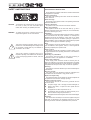
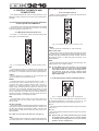
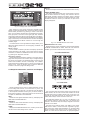
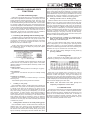
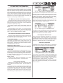
RECALL
Recalls the snapshot stored in the selected automation memory.
PRESET NUMBER display
This display reads the number of the current preset or the one
that has been selected for loading. After selection with the
PREVIOUS and NEXT switches, the display shows a decimal
point indicating that the preset has not been recalled yet. Press
the RECALL switch to confirm your selection; the point in the
display disappears.
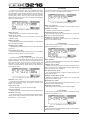
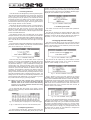
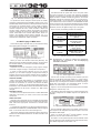
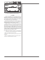
Fig. 2.14: Display with control elements
Many functions of your mixing console are controlled via the
display, including the general setup, channel processing and the
built-in effects processors. By pressing a switch in the switch
block, you can display whole groups of associated menu pages.
Each group has a menu bar on the upper right side, and each
single menu page has a tab along the top left part of the display.
A thick black line surrounding the tab indicates the active display
page. Press the keys in the switch block to the left of the display
or the PREVIOUS and NEXT switches to scroll through the
available pages.
The contrast knob on the right below the display allows you to
adjust the display brilliance to suit the lighting conditions and
viewing angle.
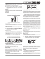
Master control
The six master controllers just below the display operate the
controls depicted in the display. They function like the channel
controllers, but feature an additional function which is enabled
by pressing the respective controller.
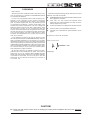
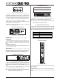
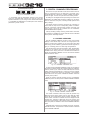
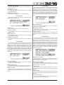
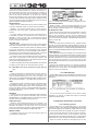
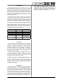
Fig. 2.16: MAIN/MONITOR level meters
MAIN/MONITOR level meter
Depending on the current configuration, this level meter displays
the MAIN or MONITOR bus levels. When the solo function is
enabled, you can also meter the level of the solo bus.
2.7 Left switch block
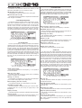
Navigation switches
Use the PREVIOUS and NEXT switches to move from page to
page within one specific menu. Another way to navigate through
the various menu pages is to repeatedly press a switch from the
switch block located to the left of the display. The CANCEL
switch activates the CANCEL button in various menu pages and
dialog boxes, while the ENTER switch performs different
functions in the menu pages and dialog boxes.
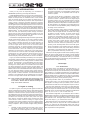
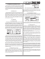
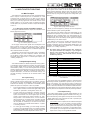
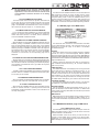
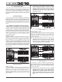
2.6 Snapshot automation: switches and displays
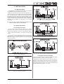
Fig. 2.17: Left switch block
2.7.1 Fader bank
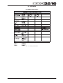
Fig. 2.15: Snapshot automation
Almost all settings for the control of audio parameters, except
for the analog level controls, can be stored in any of the 128
snapshot automation memories. The switches and LED display
in the snapshot automation section give you direct access to
these memory locations. Further information on this can be found
in chapter 10 “SNAPSHOT AUTOMATION”.
NEXT
Selects the next highest automation memory, and displays the
SNAPSHOT AUTOMATION menu.
PREVIOUS
Selects the next lowest automation memory, and displays the
SNAPSHOT AUTOMATION menu.
STORE
Displays the STORE SNAPSHOT menu, in which you can name
and store the current settings of the console.
16
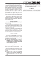
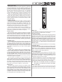
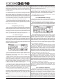
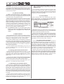
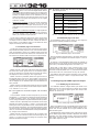
Fig. 2.18: Fader bank
The 16 channel strips are used to control all 32 inputs and 16
master busses, the four aux and four effect masters as well as
the eight returns from the built-in effects units. To this end, your
console has four fader banks with 16 channel strips each. The
master fader always controls the stereo main mix.
The fader bank switches (CH 1-16, CH 17-32, BUS OUT 1-16
and AUX/FX) select the active fader bank. The switches and
controls in the channel strips are always assigned to the same
channel as the faders.
The fader menu reads the levels of all faders in the current
fader bank. If faders or mutes have been organized in groups,
each group has a specific letter assigned to it in the square field
above the faders (mute groups on top of fader groups). All
faders or mutes with the same letter are grouped together.
2. CONTROL ELEMENTS AND CONNECTORS