1
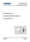
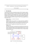
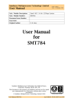
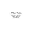
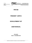
Sundance Multiprocessor Technology Limited User Manual Form : QCF42 Date : 11 February 2009 Unit / Module Description: Standalone Carrier Board (single-module size) Unit / Module Number: SMT111 Document Issue Number: 1.0 Issue Date: 21st May 2010 Original Author: Sebastien Maury User Manual for SMT111 Sundance Multiprocessor Technology Ltd, Chiltern House, Waterside, Chesham, Bucks. HP5 1PS. This document is the property of Sundance and may not be copied nor communicated to a third party without prior written permission. © Sundance Multiprocessor Technology Limited 2009 User Manual SMT111 Last Edited: 21/05/2010 16:53:00 Revision History Issue 1.0 Changes Made Initial release User Manual SMT111 Page 2 of 18 Date Initials 21/05/2010 SM Last Edited: 21/05/2010 16:53:00 Table of Contents 1 Introduction ..................................................................................................................... 5 2 Related Documents ........................................................................................................ 6 2.1 Referenced Documents.............................................................................................. 6 2.2 Applicable Documents............................................................................................... 6 3 Acronyms, Abbreviations and Definitions .............................................................. 7 3.1 4 Acronyms and Abbreviations ................................................................................... 7 Functional Description.................................................................................................. 8 4.1 Block Diagram.............................................................................................................. 8 4.2 Module Description .................................................................................................... 9 4.2.1 Xilinx FPGA device ................................................................................................. 9 4.2.2 USB 2.0 controller device...................................................................................... 9 4.2.3 Quad UART............................................................................................................ 10 4.2.4 Flash memory device........................................................................................... 10 4.2.5 JTAG_IN and JTAG_OUT (LVTTL I/Os) connectors ....................................... 10 4.2.6 Module (TIM) site.................................................................................................. 11 4.2.7 Sundance Local Bus (SLB) connector ................................................................ 11 4.2.8 Rocket-IO Serial Link (RSL) connector ............................................................. 11 4.2.9 External power supply connector ..................................................................... 11 4.2.10User LEDs............................................................................................................... 12 4.2.11RESET push-button ............................................................................................. 13 4.2.124-position DIP switch ......................................................................................... 13 4.2.13Jumper (JP7) .......................................................................................................... 14 4.2.14Xilinx JTAG connector......................................................................................... 14 5 Footprint ......................................................................................................................... 15 5.1 Top View ..................................................................................................................... 15 5.2 Bottom View............................................................................................................... 16 5.3 Photograph................................................................................................................. 16 6 Pinout............................................................................................................................... 17 7 Support Packages ......................................................................................................... 17 8 Physical Properties....................................................................................................... 17 9 Safety ............................................................................................................................... 17 10 EMC .................................................................................................................................. 18 User Manual SMT111 Page 3 of 18 Last Edited: 21/05/2010 16:53:00 Table of Figures Figure 1: SMT111 - Block Diagram ........................................................................................ 8 Figure 2: 12Vdc Power Supply connector – pinout ........................................................... 12 Figure 3: User LEDs ................................................................................................................. 12 Figure 4: RESET push-button (SW2) .................................................................................... 13 Figure 5: Jumper (JP7)............................................................................................................. 14 Figure 6: Xilinx JTAG connector ........................................................................................... 14 Figure 7: SMT111 - PCB Top view ........................................................................................ 15 Figure 8: SMT111 - PCB Bottom view.................................................................................. 16 Figure 9: SMT111 powered-up ............................................................................................. 16 User Manual SMT111 Page 4 of 18 Last Edited: 21/05/2010 16:53:00 1 Introduction The SMT111 is a single-module (TIM) site, and Sundance Local Bus (SLB) FPGA mezzanine card standalone carrier board. This carrier board features several external I/O interfaces. The main features of the SMT111 are: Single 12Vdc power input is required, and the on-board DC-DC power converters produce the necessary TIM supplies, TIM and SLB carrier board, TIM comports connected to the SLB, USB 2.0 interface connected to one TIM comport, UART and RS232 interfaces, On-board Flash memory to store the module configuration/application, JTAG input and output. The following connectors are provided to interface to: 12Vdc Power connector (to power the carrier board), TIM connectors (to plug any of TIM module), USB 2.0 (to interface to a computer/laptop/host-based system), JTAG IN and JTAG OUT (to access any TI DSP processor), Four RS232 (accessible from the Xilinx Spartan-3 FPGA or the USB controller), Reset push-button (to re-initialise the carrier board), One Rocket-IO Serial Link (RSL) (accessible either from top/bottom), Xilinx JTAG Header (to access the Xilinx devices through the JTAG chain), Sundance Local Bus (SLB) FPGA mezzanine slot (with SLB power connector), MicroSD Flash socket. User Manual SMT111 Page 5 of 18 Last Edited: 21/05/2010 16:53:00 2 Related Documents 2.1 Referenced Documents Sundance Local Bus (SLB) specification document Sundance Rocket-IO Serial Link (RSL) specification document Texas Instruments Module (TIM) specification document Comport specification document Similar products: SMT148-FX: Standalone carrier board with 4-module sites and I/O facilities SMT118: Standalone carrier board with 3-module sites and I/O facilities SMT180: Standalone carrier board with 8-module sites 2.2 Applicable Documents SMT6300: Driver package with support for the SMT111 carrier board (USB interface) SMT6002: Flash programming utility tool for FPGA-only modules SMT6048: Host-side software functions and API for the USB 2.0 interface User Manual SMT111 Last Edited: 21/05/2010 16:53:00 3 Acronyms, Abbreviations and Definitions 3.1 Acronyms and Abbreviations CP FPGA JTAG RSL SLB TIM UART USB Comport Field Programmable Gate Array Joint Test Action Group Rocket-IO Serial Link Sundance Local Bus Texas Instruments Module (module form factor commonly used by Sundance) Universal Asynchronous Receiver/Transmitter Universal Serial Bus User Manual SMT111 Last Edited: 21/05/2010 16:53:00 4 Functional Description 4.1 Block Diagram USB Connector USB2 Controller RS232 RS232 RS232 RS232 Quad UART JTAG Programming Header DIP switch Flash Memory 64MBytes FPGA Spartan-3 microSD socket User LEDs CP0 & 3 JTAG Out TTL I/O Primary TIM Connector JTAG In CP1,2,4,5 SLB Secondary TIM Connector Reset Control SLB Power Reset Switch +/-12V, +5V, +3.3V 12Vdc Input RSL Pass-through Connector Power Converters Figure 1: SMT111 - Block Diagram User Manual SMT111 Page 8 of 18 Last Edited: 21/05/2010 16:53:00 4.2 Module Description 4.2.1 Xilinx FPGA device The primary controlling device on the SMT111 is a Xilinx Spartan-3 XC3S200 FPGA. This device has a speed grade of -4, and it is an FTG256 package. The main feature of this FPGA device is to provide the interface between a TIM Comport, the USB and the UART controllers. The FPGA design for the USB interface is used on the SMT111 carrier board, and allows applications (3L Diamond applications) to be downloaded to the TIM. For UART configurations, a simple protocol may be used to access the internal registers. The FPGA operating mode (flash programming, USB and UART) in controlled via a 4way switch. In normal operation, this Spartan-3 FPGA device is configured by a Xilinx PROM (XCF04S). It may also be accessed and configured via a Xilinx compatible JTAG header. 4.2.2 USB 2.0 controller device A Cypress CY7C68013A is used to implement a USB 2.0 interface. The Cypress part, in addition to providing USB functions with a FIFO type interface, also contains a UART, and an 8051 micro-controller. This device operates with the Xilinx Spartan-3 FPGA to provide a communication path to the TIM via Comport link #3 (Comport_3). This interface can operate at rates up to 48MBytes/s. Programs can be loaded and executed via this port using the 3L Diamond tools. The USB connector pin-out is shown here; 1 USB_ind 2 Data- 3 Data+ 4 GND Table 1: USB connector – Pinout The USB 2.0 controller device is configured from an EEPROM. After a successfully configuration of the USB device, the LED labelled "D6" is "ON". User Manual SMT111 Page 9 of 18 Last Edited: 21/05/2010 16:53:00 4.2.3 Quad UART An Oxford Semiconductor 16C954 UART provides four RS232 channels. Some Maxim MAX3241 devices perform the conversion from 3.3V LVTTL to true RS232 signal levels. The RS232 signals are available via latching IDC headers. The pin-out is shown here: Signal Pin Pin Signal DCD 1 2 RX TX 3 4 DTR GND 5 6 DSR RTS 7 8 CTS RI 9 10 - Table 2: RS232 – Pinout The 10 pin IDC headers do NOT have the standard pinout required for a direct connection to a 9-way D-type connector. 4.2.4 Flash memory device The Xilinx Spartan-3 FPGA is coupled to a 64Mbytes of flash to enable configuration of FPGA-only modules, or to store DSP applications and additional FPGA configuration files (bitstreams). A separate MicroSD (Transflash) socket connects directly to the FPGA. No FPGA IP core is provided as standard. However with the addition of a MicroBlaze processor, a full FAT file system may be implemented. 4.2.5 JTAG_IN and JTAG_OUT (LVTTL I/Os) connectors An XDS510/560 compatible 14-way 0.1” pitch DIL pin header is provided to enable debugging of a DSP module using Texas Instruments Code Composer Studio. A JTAG_OUT connector can be used to chain this carrier with any other Sundance carrier board. JTAG chaining is handled by the Xilinx FPGA. The JTAG_OUT connector can be used to carry general purpose LVTTL I/O signals. The selection of JTAG_OUT or LVTTL_I/Os is made by a DIP switch (SW1). User Manual SMT111 Page 10 of 18 Last Edited: 21/05/2010 16:53:00 4.2.6 Module (TIM) site A single module (TIM) site can accept any of Sundance’s FPGA or DSP modules. All communication ports are routed to the TIM connectors: Primary TIM connector (Top): Comport_0 and Comport_3, Secondary TIM connector (Bottom): Comport_1, Comport_2, Comport_4, and Comport_5. The Comport_3 link is routed by default to the USB 2.0 interface. The remaining Comports (Comport_1, Comport_2, Comport_4, and Comport_5) are directly connected (hardwired) to the Sundance Local Bus (SLB) connector. 4.2.7 Sundance Local Bus (SLB) connector One Sundance Local Bus (SLB) slot is available to add additional I/Os to the SMT111 carrier board. Forty eight signals from the SLB are connected to four comports on the TIM connector (Comport_1, Comport_2, Comport_4, and Comport_5). These are all LVTTL compatible. As all DSP and FPGA modules that Sundance produce use FPGA device to communicate via Comports, the SLB signals are therefore available directly by this FPGA. 4.2.8 Rocket-IO Serial Link (RSL) connector A pair of Rocket-IO Serial Link (RSL) connectors is provided on the top and bottom of the SMT111 carrier board. Four lanes of RSL signals are simply connected from the top (TIM side) to the bottom. This allows access to the TIM’s underside RSL signals. 4.2.9 External power supply connector A single 12Vdc power source is needed to power the SMT111 carrier board. On-board converters provide the following voltages: +12V 1.0A -12V 0.75A +5V 16A +3.3V 16A Table 3: Power converters – Ratings This is sufficient power to provide up to 80Watts of power for FPGA TIMs (if Vcore is derived from +5V). User Manual SMT111 Page 11 of 18 Last Edited: 21/05/2010 16:53:00 The power input connector (Molex 39-28-1083, MINI-FIT, 8-way) pin-out is shown here: Figure 2: 12Vdc Power Supply connector – pinout 4.2.10 User LEDs There are four user LEDs directly connected to the FPGA. Figure 3: User LEDs The default Xilinx Spartan-3 FPGA firmware provided by default with the SMT111 drives the LEDs to monitor some "health" status. This feature is coded in the FPGA firmware and cannot be switched off, unless the firmware is modified. When powering-off and then powering-on the SMT111 carrier board, the Xilinx Spartan-3 FPGA (located on the SMT111) configures from a Xilinx PROM. Once the configuration is successful, you should see a red LED flashing at regular intervals (the first LED down from the USB connector). You should also see D1, D2, D3 and D4 "ON". They are the 4 LEDs next to the power connector (JP2). User Manual SMT111 Page 12 of 18 Last Edited: 21/05/2010 16:53:00 4.2.11 RESET push-button The “RESET” signal is asserted during power-up, or by pressing the RESET pushbutton switch (SW2). Figure 4: RESET push-button (SW2) The red LED (third LED down from the USB connector - JP4) on the SMT111 should go off and illuminates every time you issue a hard reset (blue push-button - SW2). It indicates that the Xilinx Spartan-3 FPGA firmware is loaded and running. You should see that same result with the USB cable plugged in or not. 4.2.12 4-position DIP switch A four position DIP switch (SW1) allows for the following settings: Setting SW 1 ON OFF LVTTL I/O JTAG-OUT 2 3 4 Table 4: DIP switch (SW2) – Settings User Manual SMT111 Page 13 of 18 Last Edited: 21/05/2010 16:53:00 4.2.13 Jumper (JP7) Figure 5: Jumper (JP7) The jumper (JP7) shall NOT be removed, and remain fitted. 4.2.14 Xilinx JTAG connector A JTAG connector is available to access the Xilinx Spartan-3 FPGA and the Xilinx PROM devices using the Xilinx IMPACT tools. Figure 6: Xilinx JTAG connector Do NOT erase or reprogram the Xilinx PROM without the contentment of .Sundance since it may alter the functionalities of the SMT111 provided by default. User Manual SMT111 Page 14 of 18 Last Edited: 21/05/2010 16:53:00 5 Footprint 5.1 Top View Figure 7: SMT111 - PCB Top view User Manual SMT111 Page 15 of 18 Last Edited: 21/05/2010 16:53:00 5.2 Bottom View Figure 8: SMT111 - PCB Bottom view 5.3 Photograph Figure 9: SMT111 powered-up User Manual SMT111 Page 16 of 18 Last Edited: 21/05/2010 16:53:00 6 Pinout Contact Sundance’s technical support. 7 Support Packages The following board support packages are mandatory to use the SMT111: SMT6300: Driver package with support for the SMT111 carrier board (USB interface), SMT6002: Flash programming utility tool for FPGA-only modules. These board support packages do NOT allow to create a host-side C/C++ software application with Visual Studio C++, or similar software programming tools. It is strongly recommended to purchase the additional packages: SMT6048: Host-side software functions and API for the USB 2.0 interface, 3L Diamond: Software tool-suite to design FPGA user applications. 8 Physical Properties Dimensions 118.6mm Weight 110g. 90mm Supply Voltages Supply Current +12V 250mA +5V N/A +3.3V N/A -5V N/A -12V N/A MTBF It is recommended to use cooling fans, or other efficient cooling system. 9 Safety This module presents no hazard to the user when in normal use. User Manual SMT111 Page 17 of 18 Last Edited: 21/05/2010 16:53:00 10 EMC This module is designed to operate from within an enclosed host system, which is build to provide EMC shielding. Operation within the EU EMC guidelines is not guaranteed unless it is installed within an adequate host system. This module is protected from damage by fast voltage transients originating from outside the host system which may be introduced through the output cables. Short circuiting any output to ground does not cause the host PC system to lock up or reboot. User Manual SMT111 Page 18 of 18 Last Edited: 21/05/2010 16:53:00