1
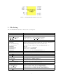
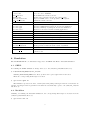
plotcircle user manual
Title
Author
Contact
Website
Release Date
Version
Rev. history
v1.0.0
plotcircle (IP core)
Nikolaos Kavvadias Courtesy of Ajax Compilers
[email protected]
http://www.ajaxcompilers.com
07 January 2013
1.0.0
07-01-2013
First public release.
1. Introduction
The PLOTCIRCLE graphics unit module is a synthesizable RTL model of a quadrant-based circle drawing
algorithm. The algorithm determines which points should be plotted in order to form a close approximation of a circle with center coordinates (xm,ym) and radius r. It can be used for drawing circles on
raster displays as well as fundamental functionality in numerous software graphics libraries.
The algorithm uses only integer operations such as addition, subtraction, bit shifting, comparison,
absolute value and conditional moves. It consists of a single loop that keeps track of the propagated
error over the x- and y-axis, which is then used for calculating four pixels (one per quadrant), during
each iteration. The loop terminates when all the possible steps over the x- or y- axes are exhausted.
The following sections provide details on the contents of the distributed IP core, which include all
necessary materials such as source files and scripts for RTL simulation and logic synthesis. Further, a
demonstration system with VGA output is provided for FPGA testing of the PLOTCIRCLE IP core.
Reference documentation for PLOTCIRCLE can be found in the /doc subdirectory in plain text,
HTML and PDF form.
2. Functional description
PLOTCIRCLE is implemented as a fully synchronous FSMD (Finite-State Machine with Datapath). The
interface diagram for streamed pixel generation is shown below. The core uses a single external clock
source, connected to signal CLK. It can be asynchronously reset with the active high signal RESET.
Signal START activates the core. Data inputs XM, YM and R are the center coordinates and circle radius,
respectively. Data outputs XOUT, YOUT are the x- and y-axis coordinates of the currently emitted pixel.
DONE signifies the end of the current computation; when VALID is raised, a new pair of outputs (XOUT,
YOUT) has been generated. READY indicates that the core can accept new input.
1
Figure 1: PLOTCIRCLE FSMD I/O interface.
3. File listing
The PLOTCIRCLE distribution includes the following files.
/plotcircle
/bench/vhdl
plotcircle tb.vhd
std logic 1164 ta.vhd
std logic textio.vhd
/doc
AUTHORS
LICENSE
plotcircle-fsmd-if.png
plotcircle-pb.pdf
README
README.html
README.pdf
VERSION
/rtl/vhdl
plotcircle.vhd
/sim/rtl sim
sim/rtl sim/bin
plotcircle.do
plotcircle.mk
/sim/rtl sim/out
plotcircle.vcd
plotcircle results.txt
/sim/rtl sim/run
plotcircle data.txt
plotcircle-ghdl.sh
plotcircle-mti.sh
/sim/rtl sim/vhdl
Top-level directory
Benchmarks VHDL directory
Self-checking testbench for the plotcircle IP.
Useful additions to the std logic 1164 package.
Draft version of the std logic textio package.
Documentation directory
List of authors.
End-user license agreement for using the “plotcircle” distribution.
PNG image illustrating the plotcircle I/O interface.
Product brief (brochure) for the PLOTCIRCLE IP core.
This file.
HTML version of README.
PDF version of README.
Current version of the PLOTCIRCLE IP core.
RTL source code directory for the IP core
RTL VHDL design file.
RTL simulation files directory
RTL simulation scripts directory
do script for Mentor Modelsim simulation.
GNU Makefile for GHDL simulation.
Dumps and other useful output from RTL simulation
Value Change Dump file generated from RTL simulation.
Diagnostic output from RTL simulation.
Files for running RTL simulations
Reference input/output data for RTL simulation.
Bash shell script for running the GHDL simulation.
Bash shell script for running the Modelsim simulation.
VHDL sources for RTL simulation
2
clockdiv.vhd
colordec.vhd
data bram.vhd
imgmap.vhd
plotcircle system.vhd
vga controller.vhd
/sw
plotcircle.bsl
plotcircle.pbm
plotcircle.ppm
plotcircle test.c
/syn/xise
/sim/xise/bin
xst.mk
/sim/rtl sim/out
plotcircle-256x256.bit
/sim/rtl sim/run
plotcircle sys-syn.sh
plotcircle system.bit
/sim/rtl sim/src
plotcircle sys s3an.ucf
Parametric clock divider.
Color decoder to RGB444.
Block-RAM based memory model.
Plotline data generation and storage (data bram).
Top-level VHDL source of the plotcircle demo system.
Parametric VGA controller.
Software utilities
Optimized BASIL model for plotcircle.
Generated PBM (binary) image from C model simulation.
Generated PPM (color) image from C model simulation.
Reference C model for the line drawing application.
Synthesis files for use with Xilinx ISE
Synthesis scripts directory
Standard Makefile for command-line usage of ISE.
Bitfiles and other useful output from synthesis
Reference bitstream for the plotcircle system.
Files for running synthesis
Bash shell script for invoking the ISE tools.
Newly generated bitstream as the result of synthesis.
Additional source files for running synthesis
User constraint file for the Xilinx Spartan-3AN starter kit development board.
4. Simulation
The PLOTCIRCLE IP core distribution supports both GHDL and Mentor Modelsim simulation.
4.1. GHDL
For running the GHDL simulation, change directory to the /sim/rtl_sim/run subdirectory:
$ cd $PLOTCIRCLE_HOME/sim/rtl_sim/run
assuming PLOTCIRCLE_HOME is the directory where the top-level /plotcircle is found.
Then, the corresponding shell script is executed:
$ ./plotcircle-ghdl.sh
The simulation produces two files, a VCD (waveform) dump named plotcircle.vcd and the diagnostic text file plotcircle_results.txt which are automatically copied to the /sim/rtl_sim/out
subdirectory.
4.2. Modelsim
Similarly, for running the Modelsim simulation, the corresponding shell script is executed from the
/sim/rtl_sim/run subdirectory:
$ ./plotcircle-mti.sh
3
As in the GHDL case, the VCD dump and the diagnostic text file are produced.
5. Synthesis
The PLOTCIRCLE IP core distribution supports both logic synthesis of a demo system that utilizes the
PLOTCIRCLE IP core for basic graphics generation. It should be noted that due to the specific block
RAM storage size of the tested device (Xilinx XC3S700AN) the visible display is limited to 256x256.
Different visible display dimensions are possible by configuring the X_OFFSET, Y_OFFSET, X_SIZE and
Y_SIZE generics of the imgmap module.
5.1. Demo system
The demo system comprises of the following components:
• plotcircle system: The top-level component.
• imgmap: Provides data content storage. Data is generated by plotcircle.
• vga controller: VGA controller for graphic (bitmap) output.
• clockdiv: Clock divider.
• colordec: Color decoder for 16-color generation.
• data bram: Synchronous read RAM model using separate address ports for writing and reading.
Reading is solely used for graphics display.
• plotcircle: The actual PLOTCIRCLE IP core component.
5.2. Running the synthesis script
For running the Xilinx ISE synthesis, change directory to the /syn/xise/run subdirectory:
$ cd $PLOTCIRCLE_HOME/syn/xise/run
and execute the corresponding script:
$ ./plotcircle_system-syn.sh
The synthesis procedure invokes several Xilinx ISE command-line tools for logic synthesis as described in the corresponding Makefile, found in the the /syn/xise/bin subdirectory.
Typically, this process includes the following:
• Generation of the *.xst synthesis script file.
• Generation of the *.ngc gate-level netlist file in NGC format.
• Building the corresponding *.ngd file.
• Performing mapping using map which generates the corresponding *.ncd file.
• Place-and-routing using par which updates the corresponding *.ncd file.
• Tracing critical paths using trce for reoptimizing the *.ncd file.
• Bitstream generation (*.bit) using bitgen.
4
Finally, the plotcircle_system.bit bitstream file is produced and the impact GUI is invoked.
From the impact GUI the following procedure is suggested (other options are also valid choices):
• Select No in the Automatically Project File Load popup screen.
• Select No in the Automatically create and save a project popup screen.
• Select Cancel in the New Impact project.
• From within the Impact Flows card (near top-left), double click on Boundary Scan.
• From the File menu, select Initialize Chain.
• Select Yes in the Auto Assign Configuration Files Query Dialog popup.
• Select the generated bitfile from the Assign New Configuration File popup for loading to the
XC3S700AN device.
• Subsequently, select Bypass in order not to load the XCF04S PROM.
• Select OK in the Device Programming Properties popup.
• Right click to the XC3S700AN device symbol.
• Select Program FPGA Only.
Remember to connect a CRT/LCD VGA monitor to the development board’s DSUB-15 connector.
6. Reference software application
The reference C application, available in the /sw subdirectory provides an implementation for Bresenham’s line generation algorithm.
There are two basic usage schemes of plotcircle_test.c.
When compiled as follows:
$ gcc -DTEST -DSTREAM -Wall -O2 -o plotcircle_test.exe plotcircle_test.c
executing plotcircle_test.exe, is used for generating the plotcircle_data.txt reference data
file:
./plotcircle_test.exe >& plotcircle_data.txt
This file should be copied to the sim/rtl_sim/run subdirectory.
Alternatively, the reference application can be compiled for generating either a PBM (monochrome)
or PPM (color) image file that emulates the VGA graphics display of the demo plotcircle system.
Thus, when compiled as follows:
$ gcc -DTEST -DSTORE -DDIAGNOSTICS -DSPARTAN3AN -DCOLOR -Wall -O2 -o
plotcircle_test.exe plotcircle_test.c
executing plotcircle_test.exe, produces the plotcircle.ppm file, while
$ gcc -DTEST -DSTORE -DDIAGNOSTICS -DSPARTAN3AN -Wall -O2 -o plotcircle_test.exe
plotcircle_test.c
is used for generating the monochrome plotcircle.pbm file.
5
7. Prerequisities
• Standard UNIX-based tools (tested with gcc-3.4.4 on cygwin/x86).
– make
– bash (shell)
For this reason, Cygwin (http://sources.redhat.com/cygwin) is suggested, since it provides a nearcomplete POSIX environment.
• GHDL simulator (http://ghdl.free.fr) or Modelsim (http://www.model.com). The latest GHDL
distribution (0.29.1, Windows version) also installs GTKwave on Windows.
• Xilinx ISE (free ISE webpack is available from the Xilinx website: http://www.xilinx.com)
• XnView [optional] is an image file viewer that supports PBM, PGM and PPM files. It is available
from here: http://www.xnview.com
6