1
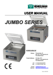
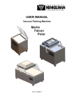
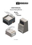
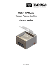
User manual Lynx 42 & Lynx 32 L-ENG-C All rights reserved. No part of this publication may be reproduced by photocopy, printing or in any other way without prior consent from Henkelman B.V 2 Table of Content Introduction ........................................................................................................................... 5 Interdictions ........................................................................................................................... 5 Machine overview.................................................................................................................. 6 Installation ............................................................................................................................ 8 Transportation and placement ............................................................................................... 8 Connecting the machine ........................................................................................................ 8 Connecting the gas flush system (if applicable) ..................................................................... 9 Starting the machine for the 1st time .....................................................................................10 Machine functions ................................................................................................................11 Function description .............................................................................................................11 Guideline for function values ................................................................................................14 Function relations .................................................................................................................16 Controlling the machine ........................................................................................................17 Control panel overview .........................................................................................................17 On/off button .....................................................................................................................17 Step button (‘right’►) ........................................................................................................17 Stop button .......................................................................................................................17 Screen ..............................................................................................................................17 Control buttons .................................................................................................................18 Viewing machine programs ..................................................................................................18 Settings ................................................................................................................................20 Authorization .....................................................................................................................20 Edit settings ......................................................................................................................20 Setting overview ...............................................................................................................22 Connecting external devices.................................................................................................23 Connecting and operating the label printer ...........................................................................23 3 Connecting and operating external vacuum..........................................................................25 Import / Export Menu ...........................................................................................................26 Exporting Data......................................................................................................................26 Importing Data ......................................................................................................................26 Creating programs/labels with the Lynx software programming tool ..................................26 Importing the created data ................................................................................................27 Maintenance .........................................................................................................................28 Important before maintenance ..............................................................................................30 Oil maintenance ...................................................................................................................30 Oil Cleaning Program........................................................................................................30 Oil maintenance ................................................................................................................30 Changing Oil / Filling Up ...................................................................................................30 Oil system overview ..........................................................................................................31 Oil types and amounts ......................................................................................................32 Changing the oil exhaust filter ..............................................................................................33 Filter housing types ...........................................................................................................33 Changing oil exhaust filters ...............................................................................................35 Replacing the sealing wire ....................................................................................................36 Replace the rubber in the silicone holder ..............................................................................37 Replace the lid gasket .........................................................................................................38 Troubleshooting....................................................................................................................39 Error Messages ....................................................................................................................39 Problem solving ....................................................................................................................39 Terms of guarantee ..............................................................................................................40 Liability .................................................................................................................................40 Warranty...............................................................................................................................40 Electrical diagram Lynx 32/42, main circuit diagram .............................................................42 4 Introduction This manual contains relevant information and instructions for starting up, operating and maintenance of the machine. Read this manual carefully before putting the machine into operation. Refer also to this manual if in doubt as to the operation and/or functioning of the machine. If the manual does not offer a solution, consult the supplier. Interdictions Never pack products that can be damaged by the vacuum. Alive animals may never be vacuumed. The guarantee and/or liability expires if damage is caused by repairs and/or changes not made by Henkelman or one of its authorized distributors. In the case of malfunctions contact the supplier. Always clean the lid with solvent-free cleaning agents. Solvents may damage the lid. The machine must always be completely voltage free before any maintenance is carried out. Always remove the plug from the wall socket. High pressure cleaning is not permitted for cleaning the machine. High pressure cleaning can cause considerable damage to electronic and other parts of the machine. Water may never be permitted to enter either the extraction nozzle of the chamber or the blow-off opening of the pump. This causes irreversible damage to the pump. Never place the machine directly next to a heat source or a steaming device (for example; a combi-steamer, dishwasher or a stove). This may cause damage to the lid. 5 Machine overview Lynx 32 1. Lid 2. Seal bar 3. Gas flush nozzle (if applicable) 4. Lid lock 5. Control Panel 6. On/off switch 7. USB port 8. Vacuum/ventilation nozzle 9. Power socket 10. Gas bottle connector 11. Oil sight glass 6 Lynx 42 1. Lid 2. Seal bar 3. Gas flush nozzle / Bagholder (if applicable) 4. Lid lock 5. Control Panel 6. On/off switch 7. USB port 8. Vacuum/ventilation nozzle 9. Power socket 10. Gas bottle connector 11. Oil sight glass 7 Installation Transportation and placement The machine must be moved or transported in an upright position. The machine may not be tilted as this can cause damage to the pump. Place the machine on a flat, level surface. This is essential for problem free operation of the machine. Enough space must be left around the machine for good ventilation. The space must be at least 5 centimetres. The ambient temperature in which the machine is operated must be between 5 ºC and 30 ºC. When operating the machine in other ambient temperatures please contact the supplier for advice. Connecting the machine Check that the voltage stated on the machine tag is the same as the mains voltage. Always connect the machine correctly to an earthed socket to avoid a fire hazard or electrical shocks (earth connection is green/yellow). The power cable must always be free and nothing may be placed on it. Replace the power cable immediately if damaged. Always disconnect the power if there are problems with the machine or during maintenance, prior to starting work on the machine. If the machine is stationary for long periods then the power should always be disconnected. 8 Connecting the gas flush system (if applicable) Connect the hose from the gas bottle to the hose coupling on the rear side of the machine and secure it with a hose clamp. The diameter of the hose nipple connector for the gas bottle is 6 mm. Never use flammable gasses or gas mixtures containing much oxygen. There is a danger of explosion when using the aforementioned gasses. Accidents and/or damage caused by using abovementioned gasses void all liability on the part of supplier as well as the guarantee. The gas bottles must always be correctly secured. If the gas flush function and/or the machine is not in use then the main valve of the gas bottle must always be closed. The pressure of the pressure reducing valve on the gas bottle may never be set to more than 1 bar. A higher pressure may damage the machine. For more information about the use of gas bottles, please consult an authorised gas supplier 9 Starting the machine for the 1st time 1. Check if there is enough oil in the machine. If not, please fill oil. Oil is delivered in a separate bottle. 2. Press the on/off switch. 3. Select the desired program. 4. Put the product in the vacuum bag and place it in the machine with the opening of the bag over the seal bar. 5. Close the lid. 6. Leave the machine for at least 4 hours switched on to enable the PCB battery to charge itself. 10 Machine functions Function description Pictogram What does it mean? Vacuum During the cycle, air will be removed from the chamber until Vacuum + the set value has been reached. This value can be set in %, mbar or hPa. This is the percentage or value of the pressure in the vacuum chamber related to the normal outside atmosphere of 1 bar (0%). The whole process is sensor operated. Vacuum Plus is an option that continues the vacuuming process by an additional time to create the possibility for trapped air, inside the product, to escape. Gas During the cycle, a gas is injected into the chamber and Gas + package creating a modified atmosphere to protect the shape or increase the shelf life of the product. The value of the gas function can be set in %, mbar or hPa. This is the percentage or value of the pressure in the vacuum chamber related to the normal outside atmosphere of 1 bar (0%). Optional the Gas Plus function can be programmed with an additional time to increase the amount of gas inside the package. Seal When sealing, the material of the vacuum bag will be heated 1-2 Cut-off and pressed together to create a hermetic seal. The programming for this function is done in seconds. The purpose of the 1-2 separately controlled cut-off wire is to remove the excess foil from the remaining flap. H2O The principal of the Quick Stop H2O function is that it is a H2O + very sensitive sensor vacuum controlled system. The highly sensitive H2O sensor is capable to detect the moment that liquids from the product or the product itself, start to evaporate (boiling). At that moment the control system will interfere and switch to the next step in the process. It therefore prevents the product from: drying out, losing 11 weight, spatter out of the vacuum bag, polluting the seal, chamber and the oil in the pump. The Quick Stop H2O sensor control comes standard with the H2O PLUS option. This is extra time that the vacuuming process continues after reaching the moment evaporation. Red Meat This function is especially designed for the packaging of fresh meat. It is added to the normal vacuum function to prevent degassing from the product during the sealing phase. This degassing could create air pockets and drip inside the package. Sequential With sequential vacuum it is possible to alternate vacuum vacuum and pause steps to create the opportunity for trapped air inside a product to escape from the core. In total it is possible to program a maximum of 5 steps. Soft Air Herewith it is possible to allow the air from outside, to slowly enter the chamber so the vacuum bag will shape itself slowly around the product and prevent sharp edges form the product to protrude the film, and so prevent leaks. Print With this function it is possible to create one or multiple labels per cycle that can be put on to the bag. The following data might be shown on the label: Name of the producer, Name of the product, production date, shelf life, used gas, achieved vacuum and recommended storage temperature. Oil pump The pump cleaning program ensures that the pump is cleaning thoroughly rinsed. During the program the pump and oil reaches operation temperature so that the oil absorbs the moisture and contaminants and filters them. The high temperature enables any moisture in the pump to evaporate minimising the risk for corrosion. 12 External With this function it is possible to vacuum special food Vacuum containers outside the machine. The vacuum value can be set in %, mbar or hPa. This is the percentage or value of the pressure in the food container related to the normal outside atmosphere of 1 bar. Menu Menu is used the change machine setting such as language, printing options The functions H2O (and H2O Plus), Gas (and Gas plus), 1-2 Cut-off seal require purposespecific parts to be installed in the machine before they can be activated. The Printer and External Vacuum require additional parts before they can be used. Contact your supplier for more details. 13 Guideline for function values For each function, values can be set when you are authorized as an Owner. In order to understand the consequence of the set value, the table below explains the consequences of giving a low or high value for each function. Function Range Guideline Vacuum 2-700 mbar As a rule of thumb: the higher the vacuum, the less 30-99.8% oxygen remains in the package and thus the longer is the shelf life of the product. There are exceptions to this rule. Vacuum Plus 0-20 sec This is the time that the vacuuming continues after the maximum vacuum has been reached. This to allow entrapped air to escape from the product. Gas 2-700 mbar The two main reasons for gas flushing are; first to 0-70% increase shelf life by the chemical reaction between gas and the product. Secondly to protect fragile products that otherwise will be damaged by the vacuum bag. The best way to determine the right setting is trial and error. More gas in the vacuum chamber does not always result in more gas in the packed product. Gas Plus 0.1-5.0 sec If desired gas flushing can be continued in time while the sealing system is closing. The best way to determine the right setting is trial and error. Allowing more time r does not always result in more gas in the packed product. Red Meat 2-700 mbar As a rule of thumb: the higher the vacuum, the less 30-99.8% oxygen remains in the package and hence the longer the shelf life of the product. 14 H2O 2-700 mbar If the pressure decreases, the boiling temperature of water decreases. This law of physics might cause a product to boil. Besides polluting the machine this creates a weight and quality loss to the product that is being packed. By enabling the H2O function, this special sensor will detect this point of evaporation and arranges the program to continue from vacuuming to sealing. The value that can be set is the maximum vacuum value that can be reached. Please note that this vacuum value can only be reached if the product does not start to boil. H2O Plus 0.1-5.0 sec This is the time that the vacuuming continues after detecting the evaporation point. Because of the evaporation there might occur a minor shockwave pushing all remaining air from the bag. The best way to determine the right time is trial and error. Sequential Vacuum 2-700 mbar In case the Vacuum Plus time is not effective enough 30-99.8% to allow entrapped air to escape, the Sequential Vacuum should be enabled. In a maximum of 5 steps Holding time 0.1-5.0 sec vacuuming is alternated with a holding time. Each step creates a deeper vacuum than the previous step. Seal time 0.1-6.0 sec 1-2 Cut-Off time This is the time that sealing wire and/or the cut-off wire are heated. The longer the time, the more heat is transferred to the bag. Soft-air 1-20 sec The time that the air is softly released in the chamber after sealing has taken place. To best way to determine the right time is trial and error. Pump Cleaning 15 minutes No settings to be determined. External Vacuum 2-700 mbar As a rule of thumb: the higher the vacuum, the less oxygen remains in the package and thus the longer is the shelf life of the product. There are exceptions to this rule. 15 Function relations The table below shows which functions could be activated together in a program. Seal 1-2 Cut-off seal Soft-air Printer = can be active together = cannot be activated together = same function 16 Printer Gas Plus Soft-air Gas 1-2 Cut-off seal Sequential Vacuum Seal H2O Plus Gas Plus H2O Gas Red Meat Sequential Vacuum Vacuum Plus H2O Plus H2O Red Meat Vacuum Plus Vacuum Vacuum Controlling the machine Control panel overview screen on/off step button stop Your control panel may look different, depending on the model you have. On/off button Press the ‘on/off’ button to activate and deactivate the machine. Step button (‘right’►) The button ‘right’ can be used during a packaging cycle to interrupt the active function. The cycle will automatically continue with the next function. Stop button The ‘stop’ button can be used during a packaging cycle to interrupt the complete cycle. The cycle will skip all functions and terminate the cycle. Screen The screen has four possible modes: Startup mode: it shows the current date and time during the startup of the machine. It also displays the software version installed. The user is not able to undertake any action. Navigation mode: it shows a program with its functions. The user can navigate through the different programs and view the current settings of each function. Setting mode: Where the user can view and adjust all settings. Cycle mode: When the machine has started a packaging cycle, animations of the functions are shown together with the current values of the functions. 17 From every mode a screenshot is given in the figure below. Startup mode Navigation mode Setting mode Cycle mode up enter Control buttons There are five control buttons, to navigate through the navigation- and setting mode. They are shown in the figure on the right. left right These names will be used for the navigation description in the next section. down Viewing machine programs Users can view machine programs and the active functions in the navigation mode. This is the mode that appears immediately after the startup. The figure below shows a screenshot of this mode. 18 Program no / Name Function name Function value Function overview Menu Selected function The program represents the current selected preset program. By switching to another program, other functions will be active. The program choice depends on the product that will be packaged. At the bottom of the screen an overview is displayed, that illustrates which functions are active or inactive. If the function is activated, it will be displayed in color tone. When it is inactive it is displayed in soft tone. Both tones are illustrated in the figure on the right. If the Plus functions are activated, the + illustration is displayed in color. If inactive they are displayed in soft tone. The selected function is highlighted by the green circle. The name and current value of this function appears on the screen. Machine settings can be adjusted through the menu icon on the left in the function overview. 19 To navigate: Select the desired program Use the control buttons ‘up’▲ or ‘down’▼ View the functions Use the control buttons ‘left’◄ or ‘right’►. View/edit function settings Press ‘enter’ when the function is selected. Users can view the preset settings and the owner can also edit them. (see next section ‘Settings’) Edit machine settings Press ´enter´ when the menu is selected (only accessible for the owner) Settings Authorization Users have limited access in changing the settings of the machine. They can only adjust the printer settings through the printer icon in the navigation mode. Owners of the machine are authorized to change the machine settings and all functions settings. An authorization code is requested, when the ‘enter’ button is pressed while the menu icon is selected in the navigation mode. When the owner’s code has been put in, the machine settings menu will be opened. When logged in, the function settings can be changed as well. To do so, you need to go back to the navigation mode by pressing ‘left’ ◄. The users authorization code: 0000 The owners authorization code: 1324 The machine will remember the last used authorization mode, even when the machine has been shut down. Therefore you might need to manually change the authorization setting after you have finished. Edit settings When you enter the machine- or function settings, you will enter the setting mode (see picture). It describes the basic functionalities, which are similar in all setting modes. 20 indication submenu setting icon setting name value indication for indication for pressing left more options by pressing up or down To navigate through and changing values in the setting mode: Select another setting Press ‘up’▲ or ‘down’▼ Edit selected setting Press ‘enter’ Adjust variable Use ‘up’▲ or ‘down’▼ Confirm variable When the desired setting is found, press ‘enter’ Back to navigation mode When all settings are set, press ‘left’◄ to return An overview of all possible variables is given in the table below. Variables Press ‘up’ to Press ‘down’ to Press ‘left’ or ‘right’ to Numeric Increase the value Decrease the value - Character Get a lowercase Get numbers and a Go to the previous/next alphabet* capital alphabet* character* On/off Change mode Change mode - Multiple choice Select next term Select next term - * To remove a character use the empty space character that is in between the two alphabets When functions are being activated, it could be that other functions automatically deactivate, because some functions counteract each other. See schedule Function Relations. 21 Setting overview The sitemap below gives an overview of all the settings of the machine. The sitemap shows all possible settings for all functions. 22 Connecting external devices Connecting and operating the label printer Turn off the vacuum machine and connect the printer via the USB cable to the machine. Connect the power cable of the printer. Turn the vacuum machine and the printer on. Lever s Roll carrier USB cable Power cable On/Off 23 To place a roll of labels in the machine. Pull the green levers on the side forwards and open the lid. Remove at least two labels from the backing foil. Push the roll carriers outside and place the roll between them. Then pull the dispenser down to create an opening. Now lead the label foil as shown in the picture. Close the dispenser if the label foil is correctly placed. Now close the lid and push the green button on top once. The printer now automatically goes to the next label. When using a different length of label, you have to recalibrate the printer. The above steps are equal. Just hold the green button till the light under the button blinks twice. Now the sensors register the length of the new label. For activating the printer and changing the setting, check the chapter ‘Settings’. It is not possible to change the type of font or font size of the printed text on the label. Using a label with a different size as the supplied label, might result in a situation where the printed text will be unreadable. The setting of the printer is based upon a label roll that has separate labels. The free space between two labels is used to determine the length of the label. Using a printer roll without these free spaces will not work before the printer settings have been changed. Please review the Printer manual. 24 Connecting and operating external vacuum Connect the external vacuum hose connector to the vacuum/ventilation nozzle of the machine as shown. Connect the other side of the external vacuum hose to the container that needs to be vacuumed. Make sure this container is capable of resisting and holding a vacuum. Use the control panel to select the external vacuum program (‘up’▲ or ‘down’▼) Press ‘Enter’ to start and ‘Stop’ to end the vacuum process. 25 Import / Export Menu Exporting Data The settings, service data, programs and labels can be exported through the USB connector. The files will be written on a USB-key in .txt format and can be read with a standard Windows PC. Only an authorization as ‘Owner’ or ‘Distributor’ allows access to this possibility. Importing Data Via the USB port, programs and labels can be imported from a USB-key. The data to be imported can be created using the Lynx software programming tool. Please contact your supplier for this software. Creating programs/labels with the Lynx software programming tool Installing the Lynx software programming tool Create a folder on the C-drive of your PC and name it “SoftwareLX”. Save the zipped software package “SoftwareLX” on C:\SoftwareLX. Go back to the folder C:\SoftwareLX ,unzip the software package and save it in C:\SoftwareLX. Creating a program or label Open the HTML document “SoftwareLX” on C:\SoftwareLX. If internet explorer shows a warning bar, click the button to allow the blocked ActiveX contents. 26 Select a program or label and click the “go” -button. Fill out all the data you wish to use. Click the “save”- button to save the program or label. Importing the created data Use an empty USB-stick and copy the .txt files (label… and prog..) of C:/SoftwareLX on the USB Stick. Put the USB- key into the port on the machine. In the “Menu”, select “Import/Export data” and go to “Import data”. When you confirm, the existing programs and labels will be overwritten by the data that have been programmed on the PC. Note: Never change the .txt-files by opening them in notepad or any other program. This will result in corrupt files. Note: Do not place the program and label files in a separate folder on the USB-stick. Note: The machine will show an error message after the last imported program / label file. This message is not important, your files are saved. 27 Maintenance A regular and complete maintenance is required for a long lifespan of the machine, to avoid malfunctioning and to achieve an optimal packaging result. If the machine is used intensively, it is recommended to professionally service it every 6 months. For normal use of the machine, complete servicing once a year should be sufficient (depending on location, environment and products). If there are doubts about the maintenance activities or if the machine fails to work correctly always contact the supplier. However, there are minor maintenance activities that must be carried out regularly. The following table contains an overview of these activities. 28 Time scale Activity Daily Clean the vacuum chamber, lid, and housing after use with a soft damp cloth. Make sure that no cleaning agents containing solvents are used. Make sure that no high pressure water cleaner is used. Check the oil level and replace or fill up oil when the oil is turbid or the oil level is too low. See instructions. Activate the pump cleaning program for the pump. Inspect the sealing bar for damage. Replace Teflon tape/sealing wire if the seal quality is no longer sufficient or if the Teflon tape/sealing Weekly wire is no longer tight and straight on the sealing bar. See instructions. Inspect the lid gasket and replace it when the gasket is damaged. See instructions. Inspect the transparent lid. When cracks are visible, turn off the machine immediately and contact the supplier. Every Six Replace oil. Months Replace rubber in the silicone holder. Inspect the oil exhaust filter for saturation. If saturated, replace the Yearly Four-yearly filter. See instructions. Contact the supplier for a professional service. Replace transparent lid and the lid’s gas springs. Replace membranes seal cylinder. 29 Important before maintenance If the machine is not functioning properly or if it produces strange noises, turn it off immediately with the On/Off switch and contact the supplier. If the machine is equipped with a gas flush system, always close the main valve at the bottle during standard maintenance activities. When cleaning the transparent lid, never use cleaning agents containing solvents. Check at least once a week if there are cracks in the lid. In case of cracks, turn off the machine immediately and contact the supplier. Major services must always be carried out by an authorised supplier. Oil maintenance Oil Cleaning Program Use the control panel to select the pump cleaning program (‘up’▲ or ‘down’▼). The program lasts 15 minutes and it is advisable to run it at least once a week. The program runs automatically after closing the lid. If necessary the program can be interrupted at any time using the [STOP] key. Use the conditioning program at least once a week to enhance correct and long-lasting pump operation. It is also advisable to run the program before using the machine for the first time and after the machine has been stationary for a lengthy period of time. Oil maintenance Check before starting the machine the oil in the pump. If there is too little oil or the quality of the oil is bad (unclear), replace or refill the oil before operating the machine. Always change the oil before a long period of inactivity of the machine and make sure the pump is clean and free of moisture. Changing Oil / Filling Up Draining oil If the oil is white or unclear when checked then it must be replaced. Before draining off the oil let the conditioning program run a full cycle. The dirt and moisture will be absorbed by the oil and the oil becomes thinner making draining easier. After the program has ended the oil 30 drain plug can be removed. While unscrewing hot oil fumes can escape. When the oil has drained, tilt the machine slightly so that all residual oil can drain off. After draining, mount the oil drain plug. Filling up oil After draining or when the oil level is low, oil needs to be filled up. The oil fill plug must be removed. The pump can now be filled with oil. Take care to fill with small amounts at intervals. Oil system overview Lynx 32 Remove the rear cover of the machine to gain access the oil system. 1. Oil fill plug 2. Oil inspection window 3. Oil drain plug 31 Lynx 42 1. Oil fill plug 2. Oil inspection window 3. Oil drain plug Oil types and amounts It is important to use the correct type and quantity of oil for the pump. The wrong type or too much oil could damage the pump. The ambient temperature where the machine is operated is also important for the type of oil. If the machine is used outside normal specifications regarding ambient temperature, contact the supplier. See amounts and types with related ambient temperatures in the table. Ambient Temperature Machine Type Pump Filling Standard “Cold” “Hot” Capacity (litres) Oil Type Oil Type Oil Type 10 - 30 oC 5 - 10 oC 30 - 40 oC Lynx 32 8 m3/h 0.25 Viscosity VG 32 VM 32 VS 32 Lynx 42 16 m3/h 0.4 Viscosity VG 32 VM 32 VS 32 32 Changing the oil exhaust filter The oil exhaust filter in the pump absorb and filter oil vapours. The filter should be replaced after 12 to 18 months. When the filters are saturated it is no longer possible to achieve maximum vacuum. Filter housing types Remove the rear cover of the machine to access the filter. Lynx 32 33 Lynx 42 To create access for the filter to be removed, the gas spring bracket needs to be disassembled as shown. 34 Changing oil exhaust filters Replace filter 8 m3/h – Lynx 32 Unscrew the oil exhaust filter cover and remove the filter by unscrewing it from the housing. Place a new filter and screw it tight. Please note that an O-ring should be placed at the exhaust filter inlet. Replace filter 16 m3/h – Lynx 42 Unscrew the oil exhaust filter cover and remove the filter by removing the spring plate from the housing. Place a new filter and the spring plate. Please note that an O-ring should be placed at the exhaust filter inlet. 35 Replacing the sealing wire Remove the seal bar from the machine by lifting it vertically up (1) Remove the Teflon tape from the seal bar (2) Remove the screws at the bottom of the sealing bar in order to remove the wires (3) (4) Remove the Teflon tape at top of the seal bar and stick a new piece of Teflon tape of the same length after having degreased and cleaned the bar with a dust free cloth (5) Cut a new piece of sealing wire or cut-off wire to the size of the sealing beam plus about 15 cm (± 6 inches). First attach one side of the wire at a side of the seal bar and screw it tight. Now attach the other side of the wire at the other side of the seal bar. Pull the wire by using a plier and tighten the screws at the same time (6). The sealing wires should be tight and not protrude the plastic end blocks. Cut the wire ends on both sides. Cut a piece of Teflon tape as long as the seal bar plus about 5 cm (± 2 inches). Ensure that the Teflon is stuck to the bar smoothly and without folds. Cut the Teflon tape off such that the sticky part does not get stuck on the sides, but only covers the top of the clamps (2). 36 Replace the rubber in the silicone holder The silicone holder must be inspected weekly for irregularities on the silicone rubber (mainly caused by burning by the sealing wire). If irregularities appear then the silicone rubber must be replaced. Remove the old silicone rubber from the holder. Cut a new piece of silicone rubber to the same size as the old one. The same size is very important, too short or too long will cause problems with sealing. Place the new piece in the silicone holder. Ensure that the silicone rubber is completely and evenly placed in the groove. It is also important that the surface of the silicone rubber is smooth after it is in place and doesn’t show any signs of tension. 37 Replace the lid gasket The lid gasket ensures that the vacuum chamber is completely closed during the machine cycle. This is essential for achieving a maximum vacuum. The lid gasket wears due to the extreme pressure differences and must be replaced regularly. Inspect the lid gasket weekly for tears or damage. Replace the lid gasket at least once every 6 months. Remove the old gasket rubber from the holder. Cut a new piece of rubber of the same size as the old one. When the lid rubber is too short or too long it can cause problems closing the lid or leak. Replace the new piece of gasket by pressing it into the lid. The lip of the gasket should be pointing down and outwards. The rubber must be placed evenly and without tension in the holder. The ends must be cut straight and must be laid tightly against each other to avoid leakage. 38 Troubleshooting Error Messages The message “Please check cover!” will appear on the screen when the lid is not closed properly. Wait until the message disappears and re-start the cycle again by closing the lid firmly. Problem solving Control panel is not Connect the machine to the power socket illuminated Check / replace the main fuse Check / replace the fuse of the control transformer Control panel is on but no Check / replace the fuse of control transformer activity after closing the lid Check / adjust / replace the lid switch Check / replace the circuit board fuse Check / adjust vacuum setting of the program Check if extraction opening is not covered Check level and/or contamination of the oil in the pump Check / replace the oil exhaust filter Check / replace the lid gasket Check if extraction opening is not covered Check level and/or contamination of the oil in the pump Check / replace the oil exhaust filter Vacuum bag is not properly Check / adjust sealing setting of the program sealed Check / replace the Teflon tape Check / replace the silicone in the silicone holder Check / clean the inside of the vacuum bag for contamination Decrease the setting for gas flush (if activated) Insufficient gas in the Check / open / replace the gas bottle vacuum bag Check / adjust gas flush setting of the program Insufficient end-vacuum Vacuuming process is slow For all other problems please contact the supplier. 39 Terms of guarantee This manual has been established with care. Henkelman B.V. does not accept liability for errors in this manual and/or consequences of misinterpretation of the instructions. Henkelman B.V. is not liable for damages and/or problems that arise from using spare parts that are not supplied by Henkelman B.V. Henkelman B.V. reserves the right to change specifications and/or spare parts without prior notification. Liability 1. We exclude all liability as far as it is not provided by law. 2. Our liability shall never exceed the total amount of the machine value in question. 3. Barring the generally applicable legal rules of public order and good faith we are not liable to pay for any damage of any sort whatsoever, directly or indirectly, including business losses, to movable or immovable property, or to persons, either at the opposing party as at third parties. 4. We are in any case not liable for damages arising from or cause by the use of the product supplied or by the unsuitability of it for the goal for which the other party purchased it. Warranty Subject to the following limitations, the warranty period for products supplied by Henkelman is at least 12 months, as of the date indicated on the purchase document. This warranty is limited to manufacturing and machining defects and does therefore not cover breakdowns involving any part of the product that is exposed to any form of wear and tear. Normal wear and tear that can be expected with the use of this product is therefore hereby excluded. 1. Henkelman’s responsibility is limited to replacing parts found to be defective; we shall not acknowledge claims for any other kind of damage or costs. 2. The guarantee automatically expires due to overdue or sloppy maintenance. 3. If there are doubts about the maintenance activities or if the machine fails to work correctly always contact the supplier. 4. The warranty does not apply if the defect is the result of incorrect or negligent use, or maintenance that is contrary to the instructions given in this manual. 5. The warranty lapses if repairs or modifications on the product have been carried out by third parties. 40 6. Defects due to damage or accidents deriving from outside factors are excluded from the warranty. 7. If we replace parts in compliance with the obligations of this warranty then the replaced parts become our property. The stipulations of the warranty and liability are part of the general terms and conditions of sales, which can be send to you if requested. 41 Electrical diagram Lynx 32/42, main circuit diagram 42 Electrical diagram Lynx 32/42, control diagram 43 Electrical index Lynx 32, (1) Control diagram 002-PCB Main circuit diagram 011 Machine serie Lynx 32 Revision (from-Untill) Power (V/~/Hz) 230-1-50 Seal configuration Front Pomp capacity 008 M3/h Seal type Double / Cut-off Main electrical supply: L1 Phase 1 N Neutral PE Ground connection Overload devices: Fuse main entrance Fuse seal transformer Fuse control transformer F1, F2 F4 F6 F7 Fuse PCB F8 Pump: Pump type 8 M3/h Capacity 0,35 kW 44 Part number: 0232014 Specification: 10 Amp. Slow Size: 5 x 20 mm Part number: 0232027 Specification: 3,15 Amp. Slow Size: 5 x 20 mm Part number: 0232016 Specification: 0,5 Amp. Slow Size: 5 x 20 mm Part number: 0232017 Specification: 2,5 Amp. Slow Size: 5 x 20 mm Part number: 0232014000 Electrical index Lynx 32, (2) Transformers: Seal transformer Tr.1 Part number: 0223017 Input: 220-230 Volt Capacity: 500 Va Output: 10 Volt ED: 10 % Used transformer Tr.1 Connection: stand alone Control transformer Tb.1 Part number: 0223011 Input: 220-230 Volt Capacity: 60 Va Output 1: 24 Volt Output 2: 9 Volt ED: 100 % R1 Connection: Stand alone Pump K1 Part number: 0221007 Seal K2 Part number: 0221007 S2 Part number: 0220006 MS1 Electrical connections: 2 Seal bar: Used Seal bar Contactors: Switches: Control switch ON/OFF Micro switch: Switch start cycle Valves: Gas Valve Y2 Seal Valve Y3 Soft-air Valve Y4 Decompression Valve Y5 45 Electrical index Lynx 42, (1) Control diagram 002-PCB Main circuit diagram 011 Machine serie Lynx 42 Revision (from-Untill) Power (V/~/Hz) 230-1-50 Seal configuration Front Pomp capacity 016 M3/h Seal type Double / cut-off Main electrical supply: L1 Phase 1 N Neutral PE Ground connection Overload devices: Fuse main entrance Fuse seal transformer Fuse control transformer F1, F2 F4 F6 F7 Fuse PCB F8 Pump: Pump type 16 M3/h Capacity 0,55 kW 46 Part number: 0232014 Specification: 10 Amp. Slow Size: 5 x 20 mm Part number: 0232018 Specification: 5 Amp. Slow Size: 5 x 20 mm Part number: 0232016 Specification: 0,5 Amp. Slow Size: 5 x 20 mm Part number: 0232017 Specification: 2,5 Amp. Slow Size: 5 x 20 mm Part number: 0232014000 Electrical index Lynx 42, (2) Transformers: Seal transformer Tr.1 Part number: 0223019 Input: 220-230 Volt Capacity: 700 Va Output: 15 Volt ED: 10 % Used transformer Tr.1 Connection: stand alone Control transformer Tb.1 Part number: 0223011 Input: 220-230 Volt Capacity: 60 Va Output 1: 24 Volt Output 2: 9 Volt ED: 100 % R1 Connection: Stand alone Pump K1 Part number 0221007 Seal K2 Part number 0221007 S2 Part number 0220006 MS1 Electrical connections: 2 Seal bar: Used Seal bar Contactors: Switches: Control switch ON/OFF Micro switch: Switch start cycle Valves: Gas Valve Y2 Seal Valve Y3 Soft-air Valve Y4 Decompression Valve Y5 47 48 Postal Address P.O.Box 2117 5202 CC ’s-Hertogenbosch The Netherlands Address Titaniumlaan 9 5221 CK ’s-Hertogenbosch The Netherlands Tel Fax (+31) (0) 73 621 3671 (+31) (0) 73 622 1318 E-mail Information [email protected] www.henkelman.com